Quick Summary (TL;DR):
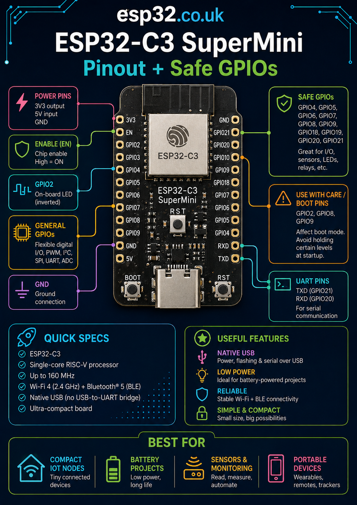
The ESP32-C3 SuperMiniAliExpress price is a tiny third-party ESP32-C3AliExpress price board built around a 160 MHz single-core RISC-V processor with 2.4 GHz Wi-Fi, Bluetooth LE, native USB and usually 4 MB flash. On the common 16-pin layout, the easiest GPIOs to start with are GPIO0, GPIO1, GPIO3 and GPIO10. GPIO4–7 are normally usable if you do not need external JTAG, GPIO20/21 are useful UART pins, while GPIO2, GPIO8 and GPIO9 are boot-strapping pins. GPIO8 usually drives the onboard blue LED and GPIO9 is normally connected to the BOOT button. GPIO18/19 carry the board’s native USB connection and are normally not exposed on the header. For analog sensing, prefer GPIO0–4 (ADC1); GPIO5 is ADC2 and has more limitations. Because “SuperMini” is not an official Espressif board design, antenna layout, regulator quality, LEDs and even small PCB details can vary between sellers.
Materials You’ll Need
| Item | Why you need it |
|---|---|
| ESP32-C3 SuperMiniAliExpress price | Main development board |
| USB-C data cableAliExpress price | Power, programming and USB Serial/JTAG |
| Breadboard | Quick prototyping |
| Dupont jumper wires | Connecting sensors and modules |
| 3.3 V I²C sensor | Easy first peripheral test |
| LED + 220–1 kΩ resistor | Simple GPIO output test |
| Pushbutton | Simple GPIO input test |
| Multimeter | Checking 3.3 V/5 V rails and troubleshooting |
| Stable 5 V supply | Useful when the USB port or attached peripherals need more current |
The board itself is inexpensive, but the quality of very cheap SuperMini clones varies. If a project will be installed permanently, it is worth testing Wi-Fi range and power stability before soldering the board into the final enclosure.
What Is the ESP32-C3 SuperMini?
The ESP32-C3 SuperMiniAliExpress price is an ultra-compact development board built around the ESP32-C3. It became popular because it compresses the useful parts of an ESP32-C3 DevKit into a board only about 22 × 18 mm, with a USB-C connector and two rows of standard 2.54 mm header holes.
It is especially attractive for small Home Assistant nodes, ESPHome sensors, compact relays, BLE devices, ESP-NOW nodes and projects where a full-size DevKit wastes too much space.
The important catch is that “ESP32-C3 SuperMini” is a board format, not an official Espressif product. There is no single manufacturer controlling every board sold under that name. Several PCB revisions and clone designs exist, which is why different SuperMini diagrams sometimes disagree about the onboard LED, antenna layout or regulator.
The GPIO mapping is generally consistent, but always compare a pinout with the labels printed on the actual board before committing a PCB or permanent wiring harness.
ESP32-C3 SuperMini Specifications
| Feature | Typical/common SuperMini |
|---|---|
| Processor | ESP32-C3, 32-bit RISC-V single core |
| CPU speed | Up to 160 MHz |
| Flash | Usually 4 MB |
| SRAM | ESP32-C3 internal SRAM |
| Wi-Fi | 2.4 GHz 802.11 b/g/n (Wi-Fi 4) |
| Bluetooth | Bluetooth 5 LE |
| Bluetooth Classic | No |
| Zigbee / Thread | No |
| USB | Native USB Serial/JTAG through USB-C |
| Exposed GPIO | Commonly 13 GPIO |
| ADC | GPIO0–4 on ADC1; GPIO5 on ADC2 |
| DAC | No |
| Capacitive touch | No |
| Logic voltage | 3.3 V |
| Power input | USB-C or 5 V pin |
| Typical board size | About 22 × 18 mm; USB connector may extend overall length |
ESP32-C3 SuperMini Pinout
The common SuperMini layout exposes the following power and GPIO connections. The physical left/right orientation depends on which way the board is viewed, so the safest reference is the printed pin label rather than counting header positions from a photograph.
| Pin label | Main functions | Practical status |
|---|---|---|
| 5V | 5 V board supply / USB 5 V rail | Power |
| GND | Ground | Power |
| 3V3 | Regulated 3.3 V | Power |
| GPIO0 | ADC1_CH0, digital I/O, PWM, deep-sleep wake | Best general-purpose |
| GPIO1 | ADC1_CH1, digital I/O, PWM, deep-sleep wake | Best general-purpose |
| GPIO2 | ADC1_CH2, digital I/O, strapping pin, deep-sleep wake | Boot-sensitive |
| GPIO3 | ADC1_CH3, digital I/O, PWM, deep-sleep wake | Best general-purpose |
| GPIO4 | ADC1_CH4, GPIO, JTAG MTMS, deep-sleep wake | Good if JTAG not required |
| GPIO5 | ADC2_CH0, GPIO, JTAG MTDI, deep-sleep wake | Good digital GPIO; ADC caveat |
| GPIO6 | GPIO, JTAG MTCK, flexible peripheral routing | Good if JTAG not required |
| GPIO7 | GPIO, JTAG MTDO, flexible peripheral routing | Good if JTAG not required |
| GPIO8 | GPIO, strapping pin, usually onboard LED | Use with care |
| GPIO9 | GPIO, strapping pin, usually BOOT button | Avoid for external loads |
| GPIO10 | Digital I/O, PWM, flexible peripheral routing | Best general-purpose |
| GPIO20 | UART0 RX by default, general GPIO | Good if UART0 RX not needed |
| GPIO21 | UART0 TX by default, general GPIO | Good if UART0 TX not needed |
Which ESP32-C3 SuperMini GPIOs Are Safest?
For a first project, the easiest pins are the ones that do not decide boot mode and are not tied to an onboard button or LED.
Best first choices

GPIO0
GPIO1
GPIO3
GPIO10
GPIO0, GPIO1, GPIO3 and GPIO10 are the cleanest general-purpose choices on the common board. They can be used for buttons, relays, digital sensors, PWM outputs and most GPIO-matrix peripherals without fighting the SuperMini’s boot hardware.
GPIO0, GPIO1 and GPIO3 are also ADC1-capable, which makes them especially useful when a project needs an analog input as well as digital I/O.
Good GPIOs with a debugging caveat
GPIO4
GPIO5
GPIO6
GPIO7
These pins overlap the ESP32-C3’s external JTAG interface. For the vast majority of Arduino and ESPHome projects this is not a problem, because the C3 also has integrated USB Serial/JTAG and most users never attach a separate JTAG probe to GPIO4–7.
If external JTAG debugging is not required, GPIO4–7 are perfectly useful expansion pins. GPIO4 is also an ADC1 input. GPIO5 has an ADC2 function, but it is better treated primarily as a digital pin because ADC2 on the C3 has hardware/revision limitations and can also conflict with Wi-Fi operation.
Useful UART pins
GPIO20 → UART0 RX
GPIO21 → UART0 TX
GPIO20 and GPIO21 are the default UART0 pair. They can still be used as ordinary GPIO or reassigned to peripherals, but boot messages and UART console behaviour may appear on these pins.
A useful C3 advantage is that the SuperMini normally programs through native USB on GPIO18/19, not through GPIO20/21. This means a project can often repurpose GPIO20/21 for a serial sensor while continuing to flash the board through USB-C.
Boot-Strapping Pins: GPIO2, GPIO8 and GPIO9
Espressif defines GPIO2, GPIO8 and GPIO9 as ESP32-C3 strapping pins. Their logic state is sampled during reset and influences boot behaviour. After startup they can be used as ordinary GPIO, but an external circuit that forces the wrong level at reset can prevent the board from booting or entering the expected programming mode.
| GPIO | Why it needs care | Recommendation |
|---|---|---|
| GPIO2 | ESP32-C3 strapping pin | Avoid strong pull-down/pull-up loads during reset |
| GPIO8 | Strapping pin and usually onboard status LED | Prefer another pin for sensors/relays |
| GPIO9 | Boot-mode strapping pin and normally BOOT button | Reserve for BOOT unless you understand the startup circuit |
This is why a pin can appear to work perfectly after boot but cause apparently random startup failures when a relay board, transistor gate, sensor module or external pull resistor is attached.
GPIO8: Onboard LED and Strapping Pin
On the most common black ESP32-C3 SuperMini, the user/status LED is connected to GPIO8 and is normally active LOW.
LOW  → LED ON
HIGH → LED OFF
A simple Arduino test is:
const int LED_PIN = 8;

void setup() {
  pinMode(LED_PIN, OUTPUT);
}

void loop() {
  digitalWrite(LED_PIN, LOW);
  delay(500);
  digitalWrite(LED_PIN, HIGH);
  delay(500);
}
Some newer or “Plus” variants use a different LED arrangement, including addressable RGB LEDs. If GPIO8 does not behave like a simple active-low blue LED, check the exact board revision instead of assuming the board is faulty.
GPIO9: BOOT Button
GPIO9 is normally connected to the physical BOOT button. Holding BOOT while resetting the board pulls the required boot-control signal into the download configuration used for recovery/flashing.
GPIO9 can technically be read as a normal button input after startup, but it is a poor choice for driving an external relay, transistor or device that can alter its reset level. Keeping GPIO9 dedicated to BOOT avoids a large class of “board only starts when disconnected” problems.
Native USB: GPIO18 and GPIO19
One of the strongest features of ESP32-C3 is its integrated USB Serial/JTAG controller. The chip uses:
GPIO18 → USB D−
GPIO19 → USB D+
On the common SuperMini these signals go directly to the USB-C connector and are not part of the normal header pinout.
This is why the board can be so small: it does not need a separate CH340, CP2102 or other USB-to-UART chip just for programming.
The practical consequence is that losing UART0 on GPIO20/21 does not necessarily mean losing USB flashing or USB serial monitoring.
ADC Pins: Use GPIO0–4 First
ESP32-C3 contains two 12-bit SAR ADC units. On the exposed SuperMini pins:
| GPIO | ADC function | Recommendation |
|---|---|---|
| GPIO0 | ADC1_CH0 | Recommended |
| GPIO1 | ADC1_CH1 | Recommended |
| GPIO2 | ADC1_CH2 | ADC works, but pin is boot-sensitive |
| GPIO3 | ADC1_CH3 | Recommended |
| GPIO4 | ADC1_CH4 | Good if JTAG not needed |
| GPIO5 | ADC2_CH0 | Avoid as first-choice analog input |
For a Wi-Fi sensor, the most predictable analog choices are therefore GPIO0, GPIO1, GPIO3 or GPIO4. GPIO2 is electrically ADC-capable but has the boot-strapping caveat.
GPIO5 belongs to ADC2. Espressif documents ADC2 limitations on ESP32-C3, including chip-revision restrictions, and older software interfaces also share ADC2 resources with Wi-Fi. For a new design, use ADC1 unless there is a compelling reason not to.
Remember that ESP32 GPIO is not 5 V tolerant. A 5 V analog sensor output must be reduced to a safe voltage with a divider or appropriate interface circuitry before it reaches the ESP32-C3.
I²C: There Are No Mandatory SDA/SCL Pins
ESP32-C3 uses a flexible GPIO matrix, so I²C is not permanently tied to one header pair. This is important because several SuperMini diagrams show “default” SDA/SCL labels on pins that are not necessarily the best choice for a real project.
For the lowest boot risk, a simple pair is:
SDA → GPIO0
SCL → GPIO1
If those pins are needed for analog inputs, another practical choice is:
SDA → GPIO4
SCL → GPIO5
GPIO4/5 are JTAG-capable, but they are normally fine for I²C when external JTAG is not being used.
I would not choose GPIO8/9 as the default I²C pair on a SuperMini even though some online diagrams suggest it. GPIO8 drives the common onboard LED and both GPIO8 and GPIO9 participate in startup behaviour, while GPIO9 is also the BOOT button.
SPI: Flexible, but Avoid Boot Pins for Chip Select
SPI signals can also be routed through the GPIO matrix. A sensible general-purpose arrangement is:
SCK  → GPIO6
MOSI → GPIO7
MISO → GPIO4
CS   → GPIO10
This leaves the three strapping pins alone. GPIO4/6/7 overlap JTAG, but that is normally irrelevant once the board is being used as a finished application rather than with an external JTAG probe.
PWM, RMT and One-Wire Devices
Most exposed digital pins can be used for LED PWM and other routed peripheral functions. For simple PWM outputs, servos, addressable-LED control or RMT-based protocols, GPIO0, GPIO1, GPIO3 and GPIO10 remain the easiest places to start.
DS18B20, DHT22 and similar one-wire/single-wire sensors work well on GPIO10 or one of the low-risk general GPIOs.
Deep Sleep and Wake-Up Pins
For battery-operated projects, ESP32-C3 has another useful distinction: GPIO0–GPIO5 can participate in deep-sleep GPIO wake functions through the low-power domain.
That makes GPIO0, GPIO1, GPIO3 and GPIO4 particularly attractive for battery sensors that need to wake from a switch, reed contact or external logic signal.
Actual board-level sleep current can be much higher than the ESP32-C3 silicon specification because the regulator, power LED and other components remain on the SuperMini. If ultra-low current matters, measure the specific board instead of assuming every clone behaves like the bare chip.
Power Pins and 3.3 V Safety
The SuperMini normally exposes:
5V  → USB/input supply rail
3V3 → regulated 3.3 V rail
GND → ground
The ESP32-C3 itself is a 3.3 V device. GPIO inputs should not be driven directly from 5 V logic.
Also be cautious about powering high-current peripherals from the board’s 3.3 V pin. SuperMini clones use different regulators, and some cheap revisions have much less regulator headroom than a full-size Espressif DevKit.
Small I²C sensors are normally fine. Displays, relays, radios, motors and other heavier loads should have their power requirements checked separately.
Why Some ESP32-C3 SuperMini Boards Have Poor Wi-Fi
This is a genuine board-level issue worth understanding. The ESP32-C3 radio itself is not inherently weak, but some SuperMini PCB revisions use a poor ceramic-antenna layout or place nearby components too close to the antenna. Other revisions work substantially better.
Because multiple manufacturers sell nearly identical boards, two boards labelled “ESP32-C3 SuperMini” can have noticeably different RF performance.
If Wi-Fi is unstable, do not immediately blame the firmware. Test:
- the board in open air rather than inside the final enclosure
- another SuperMini from a different batch or PCB revision
- a known-good USB cable and power supply
- Wi-Fi signal strength close to the access point
- whether the antenna area is touching headers, metal or a ground plane
- a lower Wi-Fi transmit-power setting as a diagnostic test
For a permanent installation where radio reliability matters more than absolute size, an official ESP32-C3 board, a reputable third-party design, or a SuperMini variant with an external antenna may be a better choice than the cheapest anonymous board.
Arduino IDE Setup
The common SuperMini can normally be programmed as an ESP32C3 Dev Module or with a compatible ESP32-C3 board profile in the Arduino ESP32 core.
Typical Arduino settings are:
Board: ESP32C3 Dev Module
USB CDC On Boot: Enabled
CPU Frequency: 160 MHz
Flash Size: 4 MB
The exact flash mode can vary between board batches. If a board uploads but behaves strangely after reset, or if a third-party profile does not boot, try the generic ESP32-C3 profile and confirm the flash mode used by that particular board.
ESPHome Setup in 2026
ESPHome works well on ESP32-C3, and in 2026 ESP-IDF is the recommended/default direction for ESP32-C3 builds. A common SuperMini configuration uses the ESP32-C3 DevKitM-1 board definition because the SuperMini itself has no official Espressif board ID.
esp32:
  board: esp32-c3-devkitm-1
  variant: ESP32C3
  framework:
    type: esp-idf
A simple I²C configuration using low-risk pins could be:
i2c:
  sda: GPIO0
  scl: GPIO1
  scan: true
For the common active-low status LED on GPIO8:
light:
  - platform: status_led
    name: "ESP32-C3 Status LED"
    pin:
      number: GPIO8
      inverted: true
If the LED does not respond as expected, verify the board revision: some SuperMini variants use different LED hardware.
How to Enter Bootloader Mode Manually
Most C3 SuperMini boards flash automatically through native USB. If the board is not detected or a bad firmware image prevents normal programming, manual download mode usually restores access.
- Hold the BOOT button.
- Press and release RST.
- Release BOOT.
- Start the upload again.
If the computer still does not see the board, test another data-capable USB-C cable before changing firmware settings. Charge-only cables remain a surprisingly common cause of “dead board” diagnoses.
Common Problem: Board Only Boots When a Sensor Is Disconnected
This nearly always points to a startup-pin conflict. Check whether the sensor or module is attached to:
GPIO2
GPIO8
GPIO9
A breakout board with a strong pull-up or pull-down resistor can force a strapping pin to the wrong level during reset even if the GPIO behaves normally once the sketch is running.
Move the peripheral to GPIO0, GPIO1, GPIO3 or GPIO10 and test again.
Common Problem: USB Port Appears and Disappears
Because programming uses the C3’s native USB controller, firmware configuration can influence USB behaviour more directly than on a board with a separate CH340/CP2102 chip.
If USB becomes difficult after flashing new firmware:
- enter manual bootloader mode with BOOT + RST
- use a known-good USB data cable
- try a different USB port
- enable USB CDC when using Arduino if serial output is expected
- avoid repurposing USB-related functions in low-level code unless intentional
Common Problem: Analog Readings Are Unstable
First verify that the input never exceeds the permitted 3.3 V domain. Then prefer an ADC1 pin:
GPIO0
GPIO1
GPIO3
GPIO4
Avoid GPIO5/ADC2 for a new Wi-Fi design unless its limitations are understood. Also remember that ESP32 ADCs are useful for sensors and monitoring, but they are not precision instrumentation ADCs; calibration and a stable source impedance improve results.
Common Problem: Wi-Fi Works on One SuperMini but Not Another
This can be a hardware-revision problem rather than a software problem. SuperMini boards from different sellers may use different PCB antenna layouts, regulators and passive components while keeping the same pin labels.
Test both boards with the same firmware, power supply and physical position. If one has dramatically worse range, replacing the board is often more sensible than spending hours tuning code around a poor RF layout.
ESP32-C3 SuperMini vs ESP32-C6 SuperMini
| Feature | ESP32-C3 SuperMini | ESP32-C6 SuperMini |
|---|---|---|
| CPU | Single-core RISC-V, 160 MHz | Single-core RISC-V, 160 MHz + LP core |
| Wi-Fi | 2.4 GHz Wi-Fi 4 | 2.4 GHz Wi-Fi 6 |
| Bluetooth | BLE 5 | Newer BLE generation |
| Zigbee / Thread | No | Yes |
| Typical use | Cheap Wi-Fi/BLE node | New smart-home / multiprotocol node |
| Maturity / simplicity | Excellent | Very good, newer platform |
For a cheap Home Assistant temperature sensor, relay or BLE project, the C3 SuperMini remains excellent. If the project needs Thread, Zigbee or Matter experimentation, the ESP32-C6 SuperMini is the more appropriate board.
Is the ESP32-C3 SuperMini Good for Home Assistant?
Yes. For ordinary Wi-Fi ESPHome devices, the C3 is still one of the best low-cost choices. It has enough performance for sensors, switches, relays, BLE proxy tasks and compact automation nodes without paying for radios or processing power that the project may never use.
The bigger decision in 2026 is whether a new project needs the C6’s Thread/Zigbee capability. The ESP32-C3 vs ESP32-C6 comparison covers that trade-off in detail.
When the C3 SuperMini Is the Right Board
- small ESPHome sensors
- Wi-Fi MQTT nodes
- BLE sensors and scanners
- ESP-NOW projects
- compact relay controllers
- battery projects where board size matters
- USB-programmable devices
- simple low-cost IoT products and prototypes
When to Choose Something Else
Choose another ESP32 when the project needs:
- Zigbee or Thread: use ESP32-C6 or H-series hardware
- 5 GHz Wi-Fi: use ESP32-C5
- dual-core processing, cameras or larger displays: use ESP32-S3
- large HMI / multimedia processing: use ESP32-P4
- maximum RF consistency: use a reputable/official development board rather than an anonymous SuperMini clone
Quick GPIO Recommendations
| Use case | Recommended pins |
|---|---|
| Safest general GPIO | GPIO0, GPIO1, GPIO3, GPIO10 |
| Extra GPIO if no external JTAG | GPIO4, GPIO5, GPIO6, GPIO7 |
| ADC first choices | GPIO0, GPIO1, GPIO3, GPIO4 |
| UART | GPIO20 RX, GPIO21 TX |
| Onboard LED | GPIO8 on common boards, active LOW |
| BOOT button | GPIO9 |
| Boot-sensitive | GPIO2, GPIO8, GPIO9 |
| Native USB | GPIO18 D−, GPIO19 D+; normally not on headers |
| Deep-sleep wake-capable group | GPIO0–GPIO5 |
Final Recommendation
The ESP32-C3 SuperMini is still one of the best tiny ESP32 boards for inexpensive Wi-Fi and BLE projects. Its 160 MHz RISC-V core is more than sufficient for the majority of sensors, relays, MQTT devices and ESPHome nodes, and native USB keeps the board remarkably small.
The main mistake is treating every exposed pin as equally safe.
Start with:
GPIO0, GPIO1, GPIO3, GPIO10

Use when needed:
GPIO4, GPIO5, GPIO6, GPIO7
GPIO20, GPIO21

Use with boot awareness:
GPIO2, GPIO8, GPIO9
For analog measurements, prefer ADC1 on GPIO0–4. For the common onboard LED expect GPIO8 active LOW, and treat GPIO9 as the BOOT pin.
The other important lesson is that SuperMini hardware quality varies. A good C3 SuperMini is a fantastic little board. A poor clone can have weak antenna performance or an undersized regulator despite looking almost identical.
If you understand those two issues — GPIO boot roles and board-to-board hardware variation — the ESP32-C3 SuperMini is an extremely useful platform.
Related ESP32 Guides
- ESP32-C3 vs ESP32-C6: Which One Should You Use?
- ESP32-C6 SuperMini Pinout + Safe GPIOs
- ESP32-C3 Versions Compared: Best Dev Boards
- Which ESP32-C Series Should You Buy?
- ESP32 Versions Explained: Complete Chip & Board Comparison
Datasheets & External Resources
All external manufacturer and software references are collected here so the main guide remains focused on esp32.co.uk content.
- Espressif ESP32-C3 Series Datasheet — official GPIO, boot-strapping, ADC, USB, CPU and wireless specifications.
- ESP-IDF ESP32-C3 GPIO Documentation — GPIO restrictions, strapping pins, JTAG and USB GPIO guidance.
- ESP-IDF Programming Guide for ESP32-C3 — official development framework documentation.
- Arduino-ESP32 Documentation — Arduino core installation and ESP32-C3 development information.
- ESPHome ESP32 Platform Documentation — current ESP32-C3 and ESP-IDF configuration guidance.