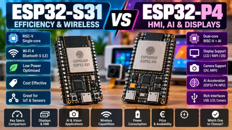
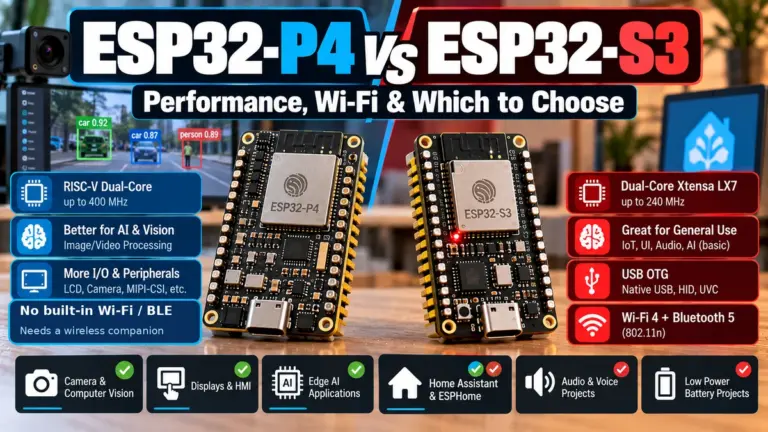
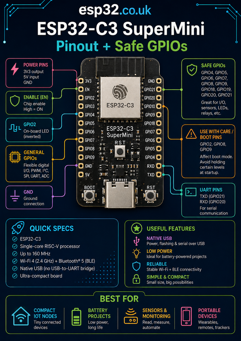
Quick Summary (TL;DR):
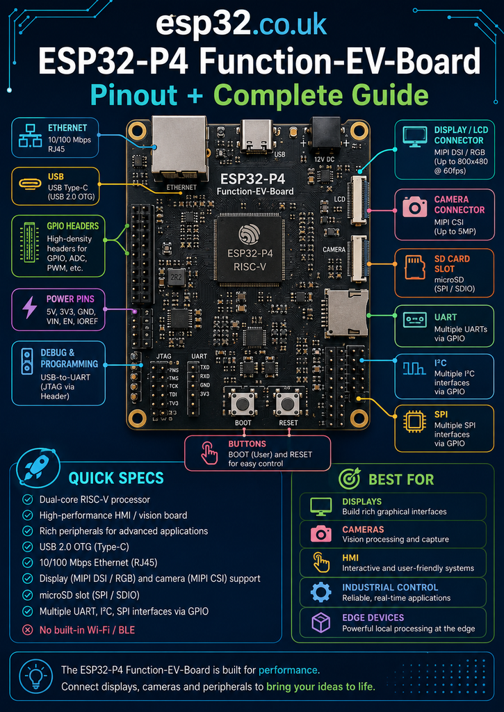
The ESP32-P4 Function-EV-Board v1.5.2 is not a normal ESP32AliExpress price DevKit. It is a high-performance multimedia development platform built around the dual-core 400 MHz ESP32-P4AliExpress price RISC-V processor, with 16 MB flash, 32 MB PSRAM, MIPI CSI camera, MIPI DSI display support, H.264 encoding, USB 2.0 OTG, 10/100 Ethernet, audio, MicroSD and extensive GPIO expansion. The ESP32-P4AliExpress price itself has no integrated Wi-Fi or Bluetooth, so the board includes a separate ESP32-C6-MINI-1 to provide 2.4 GHz Wi-Fi 6 and Bluetooth LE. For general expansion, GPIO5–8, GPIO20–23 and GPIO32–33 are among the easiest J1 pins to start with. GPIO36–38 need more care because they participate in boot/UART functions, GPIO0/1 and GPIO45 are not connected by default, and GPIO24/25 were removed from the expansion header in board revision v1.5.2.
Materials You’ll Need
The basic board is usable by itself, but the following parts unlock most of what makes the ESP32-P4 Function-EV-Board interesting.
| Item | Why you need it |
|---|---|
| ESP32-P4 Function-EV-Board v1.5.2 | Main development platform |
| USB-C data cable | Flashing, debugging and power |
| 5 V USB power supply | Recommended when driving LCD, USB devices or other peripherals |
| 7-inch 1024 × 600 MIPI DSI display kit | Optional HMI/display development |
| 2 MP MIPI CSI camera kit | Optional camera and vision projects |
| MicroSD card | Local storage, media and data logging |
| 4 Ω 3 W speaker | Use the onboard audio amplifier |
| Dupont jumper wires | Connecting external GPIO peripherals |
| Breadboard | Prototyping sensors and circuits |
| 3.3 V I²C/SPI sensor | Easy GPIO/peripheral testing |
| Ethernet cable | Testing the onboard 10/100 Ethernet port |
For someone buying the board specifically for HMI or camera development, the display + camera bundle is much more useful than purchasing the bare board alone.
The board is physically and electrically much more capable than a typical ESP32AliExpress price DevKit, so a good power supply becomes important once a large display, camera, USB host peripheral or speaker is added.
What Is the ESP32-P4 Function-EV-Board?
The ESP32-P4 Function-EV-Board is Espressif’s main development platform for the ESP32-P4AliExpress price multimedia microcontroller.
It is designed for applications such as:
- touchscreen control panels
- Home Assistant-style wall displays
- video doorbells
- network cameras
- smart appliance displays
- industrial HMIs
- vehicle dashboards
- local image processing
- USB host/device applications
- audio interfaces
- edge AI
- computer vision
This is a very different target from something like an ESP32-C3 or ESP32-C6 sensor node.
The P4 is designed to do much more processing locally.
ESP32-P4 Quick Specifications
| Feature | ESP32-P4 Function-EV-Board |
|---|---|
| Main processor | ESP32-P4 |
| Architecture | 32-bit RISC-V |
| Main CPU | Dual-core up to 400 MHz |
| Low-power CPU | RISC-V up to 40 MHz |
| Internal HP memory | 768 KB L2 memory |
| LP SRAM | 32 KB |
| Board PSRAM | 32 MB |
| Board flash | 16 MB |
| Wi-Fi | Via onboard ESP32-C6-MINI-1 |
| Wi-Fi generation | Wi-Fi 6, 2.4 GHz |
| Bluetooth | BLE via ESP32-C6 |
| Native Wi-Fi in P4 | No |
| Native Bluetooth in P4 | No |
| MIPI CSI camera | Yes |
| MIPI DSI display | Yes |
| H.264 encoder | Yes |
| JPEG codec | Yes |
| Image Signal Processor | Yes |
| Pixel Processing Accelerator | Yes |
| USB | USB 2.0 OTG + Full-Speed + Serial/JTAG |
| Ethernet | 10/100 Mbps RJ45 |
| MicroSD | Yes, 4-bit mode |
| Audio codec | ES8311 |
| Speaker amplifier | NS4150B, up to 3 W |
| ADC | Two 12-bit SAR ADCs |
| GPIO | Up to 55 at SoC level |
| Expansion | 40-pin J1 header |
The headline specification is the dual 400 MHz RISC-V cores, but the real advantage of the P4 is everything surrounding those processors.
The chip contains dedicated hardware for graphics, cameras, image processing and multimedia workloads that would normally consume a large percentage of an ESP32-S3’s CPU time.
The Most Important ESP32-P4 Fact: It Has No Radio
This is probably the most common misunderstanding around the ESP32-P4.
The ESP32-P4 chip itself does not contain Wi-Fi or Bluetooth.
That is very unusual in the ESP32 family.
The Function-EV-Board solves this by mounting a second microcontroller:
ESP32-C6-MINI-1
The architecture therefore looks approximately like this:
                    ESP32-P4
              Dual-core 400 MHz
                      │
                      │ SDIO / hosted link
                      │
              ESP32-C6-MINI-1
                      │
             ┌────────┴────────┐
             │                 │
         Wi-Fi 6              BLE
          2.4 GHz
The ESP32-P4 handles the application, display, camera, audio, USB and local processing.
The ESP32-C6 acts as the wireless communications processor.
This is an important architectural difference from:
ESP32-S3
ESP32-C5
ESP32-C6
where the main SoC itself contains the radio.
Why Espressif Split the Processor and Wireless Radio
At first, adding a second ESP32 just to provide Wi-Fi may seem unnecessarily complicated.
But it has several advantages.
The P4 can devote much more silicon area and power budget to:
- CPU performance
- memory interfaces
- image processing
- MIPI
- USB
- graphics
- DMA
- multimedia acceleration
without trying to integrate a 2.4 GHz RF subsystem into the same chip.
It also allows wireless technology to evolve separately from the main multimedia processor.
This design philosophy becomes even clearer in newer P4 development platforms that pair the P4 architecture with newer wireless companion chips.
ESP32-P4 vs ESP32-S3
It is useful to think of the P4 as sitting above the S3 for local multimedia processing, rather than simply replacing it.
ESP32-S3
Excellent for:
- small displays
- cameras
- LVGL
- audio
- USB
- moderately demanding local processing
- compact embedded products
ESP32-P4
Better suited to:
- large displays
- MIPI displays
- higher-resolution cameras
- H.264
- image processing
- complex HMI
- large PSRAM workloads
- USB host systems
- sophisticated multimedia applications
The trade-off is that the P4 board is larger, more complex and generally unnecessary for simple IoT nodes.
If the project is:
SHT40
+
Home Assistant
+
Wi-Fi
the P4 is excessive.
If the project is:
1024 × 600 touchscreen
+
camera
+
local UI
+
audio
+
Ethernet
+
Wi-Fi
the P4 suddenly makes much more sense.
ESP32-P4 Function-EV-Board v1.5.2
This article focuses specifically on:
ESP32-P4 Function-EV-Board hardware revision v1.5.2
That matters because older boards have a different pinout.
The major changes from v1.4 include:
- USB-to-UART debugging port replaced by native ESP32-P4 USB Serial/JTAG
- additional USB Full-Speed OTG Type-C connection
- GPIO24 removed from J1
- GPIO25 removed from J1
This means some older pinout images are now wrong for the current board.
If an older diagram shows:
J1 pin 27 → GPIO24
J1 pin 28 → GPIO25
that diagram is for the older board.
On v1.5.2:
J1 pin 27 → NC
J1 pin 28 → NC
This is exactly the sort of revision detail worth checking before designing a carrier board or wiring harness.
ESP32-P4 Function-EV-Board J1 Pinout
The main expansion connector is the 40-pin J1 header.
J1 pins 1–20
| J1 pin | Label | Function |
|---|---|---|
| 1 | 3V3 | 3.3 V |
| 2 | 5V | 5 V |
| 3 | GPIO7 | General GPIO |
| 4 | 5V | 5 V |
| 5 | GPIO8 | General GPIO |
| 6 | GND | Ground |
| 7 | GPIO23 | GPIO / ADC capable |
| 8 | GPIO37 | UART0 TX / boot-sensitive |
| 9 | GND | Ground |
| 10 | GPIO38 | UART0 RX / boot-sensitive |
| 11 | GPIO21 | GPIO / ADC capable |
| 12 | GPIO22 | GPIO / ADC capable |
| 13 | GPIO20 | GPIO / ADC capable |
| 14 | GND | Ground |
| 15 | GPIO6 | General GPIO |
| 16 | GPIO5 | General GPIO |
| 17 | 3V3 | 3.3 V |
| 18 | GPIO4 | GPIO / JTAG-capable |
| 19 | GPIO3 | GPIO / JTAG-capable |
| 20 | GND | Ground |
J1 pins 21–40
| J1 pin | Label | Function |
|---|---|---|
| 21 | GPIO2 | GPIO / JTAG-capable |
| 22 | NC(GPIO1) | GPIO1 not connected by default |
| 23 | NC(GPIO0) | GPIO0 not connected by default |
| 24 | GPIO36 | GPIO / strapping pin |
| 25 | GND | Ground |
| 26 | GPIO32 | General GPIO |
| 27 | NC | No connection on v1.5.2 |
| 28 | NC | No connection on v1.5.2 |
| 29 | GPIO33 | General GPIO |
| 30 | GND | Ground |
| 31 | GPIO26 | General GPIO |
| 32 | GPIO54 | GPIO / ADC capable |
| 33 | GPIO48 | GPIO / multimedia/peripheral functions |
| 34 | GND | Ground |
| 35 | GPIO53 | GPIO / ADC capable |
| 36 | GPIO46 | GPIO / multimedia/peripheral functions |
| 37 | GPIO47 | GPIO / multimedia/peripheral functions |
| 38 | GPIO27 | General GPIO |
| 39 | GND | Ground |
| 40 | NC(GPIO45) | GPIO45 not connected by default |
There are several important details hidden in this table.
Best GPIOs for General Projects
If the goal is simply to attach:
- sensors
- LEDs
- buttons
- relays
- SPI modules
- I²C peripherals
there is no reason to immediately use the more complicated pins.
Good first choices include:
GPIO5
GPIO6
GPIO7
GPIO8
GPIO20
GPIO21
GPIO22
GPIO23
GPIO32
GPIO33
These are the pins I would start with when building a general-purpose prototype.
A useful default allocation could be:
I²C SDA → GPIO21
I²C SCL → GPIO22

SPI SCK  → GPIO5
SPI MOSI → GPIO6
SPI MISO → GPIO7
SPI CS   → GPIO8

Extra GPIO → GPIO32
Extra GPIO → GPIO33
The ESP32-P4 GPIO matrix allows peripheral functions to be routed flexibly, so these are sensible practical assignments rather than permanently fixed pins.
Pins to Use With More Care
Several exposed pins deserve extra attention.
GPIO36
GPIO36 is one of the ESP32-P4 boot-strapping pins.
It can be used as normal GPIO after startup, but external circuitry should not force an inappropriate state while the chip resets.
For a beginner project:
use another GPIO unless GPIO36 is specifically needed.
GPIO37 and GPIO38
These pins are particularly important because they are:
GPIO37 → UART0 TX
GPIO38 → UART0 RX
and they also participate in ESP32-P4 boot configuration.
That makes them poor first choices for relays or other circuitry that can strongly force a logic state during reset.
They are useful as the default UART0 pair, but for another serial peripheral it is often cleaner to route another UART to ordinary GPIOs.
GPIO2, GPIO3, GPIO4 and GPIO5
These pins can participate in the external JTAG interface.
That does not mean they cannot be used.
For normal applications:
GPIO2
GPIO3
GPIO4
GPIO5
can still function as GPIO.
The issue only becomes relevant when pad-based JTAG debugging is required.
Because the board also provides USB Serial/JTAG, most hobby projects will never need to worry about the physical JTAG pin assignment.
GPIO0 and GPIO1 Are Not Actually Connected
J1 pins 22 and 23 may be particularly confusing.
The documentation shows:
NC(GPIO1)
NC(GPIO0)
These GPIOs exist on the ESP32-P4 but are not connected to the header in the normal board configuration.
They are associated with the 32.768 kHz crystal arrangement.
Making them available requires changing board resistors.
This is not something a normal user should do merely to gain two extra GPIOs.
The board already exposes enough easier pins.
Treat GPIO0 and GPIO1 as:
not available by default.
GPIO45 Is Also Disabled by Default
J1 pin 40 is marked:
NC(GPIO45)
GPIO45 can be made available by changing the board configuration associated with the SD power-control function.
Again, this requires hardware modification.
For normal projects:
treat J1 pin 40 as NC.
GPIO24 and GPIO25: Important v1.5.2 Difference
On the older v1.4 board:
J1 pin 27 → GPIO24
J1 pin 28 → GPIO25
On v1.5.2:
J1 pin 27 → NC
J1 pin 28 → NC
They were removed from the expansion header as part of the newer USB architecture.
If a project was designed around an old P4 Function-EV-Board pinout, this is one of the first compatibility points to check.
ADC Pins
ESP32-P4 contains two 12-bit SAR ADCs capable of sampling analog signals across up to 14 chip pins.
The ADC-capable GPIO ranges include:
GPIO16–GPIO23
GPIO49–GPIO54
Not all of those pins reach J1.
Useful ADC-capable pins that are exposed on the Function-EV-Board header include:
GPIO20
GPIO21
GPIO22
GPIO23
GPIO53
GPIO54
That gives the board several convenient analog inputs.
For example:
Potentiometer → GPIO20

Analog pressure sensor → GPIO21

Battery divider → GPIO22
provided the input voltage remains inside the permitted ADC range.
The ADC can operate with different attenuation settings, including a range suitable for signals approaching the 3.3 V domain.
I²C
The board is very flexible for I²C because the ESP32-P4 GPIO matrix allows signals to be routed to suitable GPIOs.
A sensible generic choice is:
SDA → GPIO21
SCL → GPIO22
This gives clean wiring for devices such as:
The board already uses I²C internally for some peripherals, including the audio codec, so advanced projects should check the board schematic and software configuration before blindly reusing internal buses.
SPI
ESP32-P4 contains multiple SPI interfaces.
A clean external SPI assignment could be:
SCK  → GPIO5
MOSI → GPIO6
MISO → GPIO7
CS   → GPIO8
This would work well for devices such as:
- SPI displays
- external ADCs
- sensors
- radio modules
- peripheral controllers
For storage, however, the board already includes a dedicated MicroSD slot, so there is usually little reason to wire an external SD card module.
UART
ESP32-P4 provides several UART controllers.
The board exposes the normal UART0 pair as:
GPIO37 → U0TXD
GPIO38 → U0RXD
These can be useful for debugging or serial peripherals.
Because GPIO37/38 have startup functions, another UART mapped to ordinary GPIOs may be preferable for external equipment such as:
- GPS
- RS-485
- Modbus
- mmWave radar
- serial displays
- industrial sensors
The ESP32-P4’s flexible routing makes this straightforward.
MIPI DSI Display
One of the biggest reasons to buy this board is the dedicated MIPI DSI display connector.
The optional official display is:
7 inch
1024 × 600
capacitive touch
This is much larger and higher resolution than the SPI TFT displays normally connected to ESP32 boards.
A normal SPI display sends pixel data through a relatively narrow serial connection.
MIPI DSI is designed for high-bandwidth display traffic.
That makes it much more appropriate for:
- LVGL dashboards
- industrial HMIs
- smart-home wall panels
- appliance displays
- graphical control systems
Connecting the Official 7-Inch Display
The official setup uses the MIPI DSI ribbon cable plus two ordinary GPIO connections.
The default control arrangement is:
MIPI DSI → display image data

GPIO27 → LCD reset
GPIO26 → backlight PWM
The display adapter can be powered independently through USB or from the board’s 5 V rail if enough power is available.
This creates an important practical consideration:
If the official LCD configuration is being used:
GPIO26
GPIO27
should not also be allocated to unrelated peripherals.
Camera Interface
The board contains a dedicated MIPI CSI connector.
The optional camera kit uses a:
2 MP MIPI CSI camera
MIPI CSI is fundamentally different from the older parallel-camera arrangement commonly seen on ESP32-CAM and ESP32-S3 boards.
The P4 also includes dedicated image-processing hardware such as:
- Image Signal Processor
- JPEG codec
- Pixel Processing Accelerator
- H.264 encoder
That means the processor can do significantly more than simply receive pixels.
It can build complete imaging pipelines.
H.264 Hardware Encoder
This is a major P4 capability.
On previous ESP32 devices, serious video encoding is difficult because the CPU must perform too much of the work.
The P4 includes a dedicated H.264 encoder.
That makes applications such as:
Camera
↓
Image processing
↓
H.264 encode
↓
Ethernet / Wi-Fi
much more realistic.
Potential applications include:
- video doorbells
- network cameras
- inspection systems
- baby monitors
- industrial vision
- local video recording
This is one of the clearest examples of why P4 should not be compared only by CPU clock speed.
32 MB PSRAM Matters More Than It Sounds
The board’s 32 MB PSRAM is enormously useful for multimedia applications.
Consider a full 1024 × 600 RGB565 framebuffer:
1024 × 600 × 2 bytes
≈ 1.23 MB
Double buffering already needs:
≈ 2.46 MB
Add:
- graphics assets
- camera frames
- video buffers
- LVGL memory
- networking
- application state
and the memory requirement climbs quickly.
This is why large PSRAM matters much more on P4 than on a simple temperature-sensor board.
16 MB Flash
The Function-EV-Board includes:
16 MB SPI flash
This is enough for:
- large firmware
- OTA partitions
- graphical assets
- fonts
- application resources
- web resources
- configuration storage
For large media files, use the MicroSD card instead of filling internal flash.
MicroSD Card
The onboard MicroSD slot operates in 4-bit mode.
That offers significantly better throughput than a typical one-bit SPI SD implementation.
Potential uses include:
- video recording
- image storage
- audio files
- data logging
- configuration files
- UI assets
- firmware resources
For an HMI or camera system, having fast removable storage directly on the board is extremely useful.
Ethernet
The board includes a proper:
10/100 Mbps RJ45 Ethernet port
The ESP32-P4 contains an Ethernet MAC, while the development board adds the external PHY hardware required to connect it to real Ethernet.
Ethernet is particularly useful for:
- industrial HMIs
- wall controllers
- network cameras
- building automation
- fixed installations
- high-reliability networking
For a device permanently installed in a wall or cabinet, Ethernet can be preferable to Wi-Fi.
It also allows the P4 application to reserve the C6 wireless connection for situations where wireless access is actually required.
USB Is Much More Capable Than on a Normal ESP32 Board
The v1.5.2 Function-EV-Board exposes several different USB paths.
USB Serial/JTAG Type-C
Best for:
- flashing
- Serial output
- debugging
- JTAG
This should normally be the first port used during development.
USB Full-Speed Type-C
Provides USB 2.0 Full-Speed functionality.
USB 2.0 High-Speed Type-C
Connected to the P4’s high-speed OTG interface.
When used through this connector, the P4 acts as a USB device.
USB 2.0 Type-A
The board can instead act as a USB host.
The Type-A host port can provide up to approximately:
500 mA
to a connected USB device.
The high-speed USB Type-C device port and Type-A host port share the same OTG interface and therefore cannot be used simultaneously.
What Can USB Host Be Used For?
Potential projects include:
- USB keyboard input
- USB mouse
- USB flash drive
- barcode scanner
- USB serial adapter
- game controller
- USB instrumentation
- custom HID hardware
This makes P4 much more interesting for embedded terminals and HMI systems.
Audio Hardware
The Function-EV-Board contains a surprisingly complete audio system.
ES8311 audio codec
Provides:
- ADC
- DAC
- microphone path
- headphone/audio processing
- I²S interface
- I²C control
Onboard microphone
Can be used for:
- voice input
- sound detection
- recording
- acoustic analysis
NS4150B amplifier
Provides approximately:
3 W mono output
and can drive a:
4 Ω / 3 W speaker
This means a complete voice-capable touchscreen controller can be built without adding a separate external audio board.
ESP32-C6 Wireless Companion
The onboard ESP32-C6-MINI-1 provides:
- 2.4 GHz Wi-Fi 6
- Bluetooth Low Energy
to the main ESP32-P4 through a hosted architecture.
A useful way to think about the board is:
ESP32-P4
= application computer

ESP32-C6
= wireless modem / coprocessor
That is conceptually similar to using a separate Wi-Fi chipset with a more powerful application processor.
Does the Board Support Zigbee or Thread?
The ESP32-C6 silicon itself contains IEEE 802.15.4 hardware.
However, on the P4 Function-EV-Board it is primarily documented and used as the Wi-Fi/BLE communications module for the P4.
Do not assume that buying the board automatically gives a plug-and-play P4 Zigbee or Thread application architecture.
If Zigbee or Thread is a core requirement, check the specific software framework and radio-coprocessor configuration intended for that project rather than assuming the C6 behaves like a standalone C6 DevKit.
Programming the ESP32-P4
The recommended port on v1.5.2 is the:
USB Serial/JTAG Type-C port
Under normal conditions:
Connect USB
↓
Select ESP32-P4 target
↓
Build
↓
Flash
↓
Monitor
If manual download mode is required:
- Hold BOOT.
- Press and release RESET.
- Release BOOT.
- Flash the firmware.
The BOOT button controls the required startup state for firmware download.
ESP-IDF
ESP-IDF remains the most important development environment for serious P4 work.
A normal target setup begins with:
idf.py set-target esp32p4
Then:
idf.py menuconfig
and:
idf.py build
idf.py flash
idf.py monitor
or simply:
idf.py flash monitor
For projects using:
- MIPI
- camera
- H.264
- complex USB
- ESP-Hosted
- Ethernet
- advanced multimedia
ESP-IDF is generally the most complete environment.
Arduino Support in 2026
ESP32-P4 is now listed as a stable Arduino-ESP32 target.
That is a significant improvement over the early life of the P4.
Arduino support includes many normal ESP32 peripherals such as:
- GPIO
- ADC
- UART
- SPI
- I²C
- USB
- Ethernet
- Wi-Fi through ESP-Hosted
But there is an important distinction.
Arduino support for the processor does not mean every advanced P4 multimedia feature is wrapped in a simple Arduino library.
For straightforward GPIO and connectivity:
Arduino is increasingly practical.
For advanced:
MIPI CSI
MIPI DSI
ISP
H.264
complex multimedia
ESP-IDF remains the more natural development environment.
LVGL
The Function-EV-Board is an excellent platform for LVGL.
Espressif provides examples for both:
- LVGL 8
- LVGL 9
using the 7-inch display.
This is one of the strongest real-world use cases for the board.
A P4-based HMI can combine:
1024 × 600 touchscreen
+
LVGL
+
Ethernet
+
Wi-Fi
+
camera
+
audio
+
MicroSD
on one development platform.
That is far beyond what the classic ESP32 was originally designed to do.
ESP-Brookesia
Espressif also demonstrates the board with ESP-Brookesia, a higher-level graphical framework designed for rich embedded interfaces.
The official P4 examples include a phone-like interface demonstrating multiple applications using:
- MIPI DSI
- MIPI CSI
- audio
- MicroSD
- C6 networking
This is useful because it shows the intended direction of the P4 ecosystem.
It is not just a faster sensor microcontroller.
It is aimed at rich embedded user interfaces.
Is ESP32-P4 Good for Home Assistant?
For an ordinary Home Assistant sensor:
No.
Use:
instead.
For a Home Assistant wall panel, however:
Yes — potentially excellent.
A P4 wall panel could combine:
- 7-inch touchscreen
- local dashboard/interface
- Ethernet
- Wi-Fi
- speaker
- microphone
- proximity/presence sensors
- local camera
- physical buttons
The board is far more suited to being the interface to a smart home than being a simple hidden sensor.
Is ESP32-P4 Good for ESPHome?
For a conventional ESPHome sensor, P4 is unnecessary.
The strengths of the P4 are mostly outside the areas where ESPHome traditionally shines.
For example:
ESP32-C3 + SHT40
is a far better solution for a small temperature sensor.
The P4 makes sense when building something much richer, such as a custom display/controller where ESP-IDF, LVGL or a dedicated application framework is being used.
Is ESP32-P4 Good for AI?
Yes, within microcontroller limits.
The P4 CPU includes custom AI/DSP-oriented extensions and the chip contains several dedicated image-processing accelerators.
Useful edge workloads can include:
- image preprocessing
- object classification
- sensor inference
- vision pipelines
- audio processing
- wake-word style tasks
- lightweight local models
But P4 should not be confused with a desktop GPU or a large neural-processing accelerator.
Its advantage is performing useful AI/vision work locally, cheaply and at embedded power levels.
Best Uses for the ESP32-P4 Function-EV-Board
The board is particularly strong for:
Smart-home control panels
Large touchscreen, Wi-Fi, Ethernet, audio and local UI.
Video doorbells
Camera + H.264 + audio + network connectivity.
Network cameras
MIPI camera + image processing + Ethernet/Wi-Fi.
Industrial HMI
Display + Ethernet + GPIO + USB + local processing.
Vehicle dashboards
Fast graphics, display connectivity, sensors and local interfaces.
Computer-vision experiments
MIPI camera, ISP, PPA, JPEG and large PSRAM.
USB appliances
Host and device support allows integration with standard USB hardware.
When You Should Not Buy It
Do not choose the P4 Function-EV-Board merely because:
400 MHz
>
240 MHz
For many ESP32 applications, CPU speed is almost irrelevant.
You probably do not need P4 for:
- DS18B20 sensors
- BME280 nodes
- simple relays
- BLE proxies
- basic MQTT
- simple ESPHome devices
- battery-powered sensors
- tiny embedded projects
The board becomes valuable when several of its high-end features are used together.
P4 Function-EV-Board vs ESP32-S3 DevKit
Choose ESP32-S3 when:
- smaller board matters
- Wi-Fi must be integrated directly
- project uses a modest SPI/RGB display
- project needs a basic camera
- cost matters
- Arduino simplicity matters
Choose ESP32-P4 Function-EV-Board when:
- large MIPI display is required
- MIPI camera is required
- H.264 matters
- large PSRAM is needed
- USB host is important
- Ethernet matters
- advanced HMI/vision processing is central to the design
They overlap, but the P4 is clearly aimed at the more demanding end of the market.
Quick GPIO Recommendations
Best starting GPIOs
GPIO5
GPIO6
GPIO7
GPIO8
GPIO20
GPIO21
GPIO22
GPIO23
GPIO32
GPIO33
ADC-friendly exposed GPIOs
GPIO20
GPIO21
GPIO22
GPIO23
GPIO53
GPIO54
Default UART0
GPIO37 → TX
GPIO38 → RX
Use with care because of startup roles.
Official LCD configuration
GPIO27 → LCD RESET
GPIO26 → LCD backlight PWM
Boot-sensitive GPIOs exposed on J1
GPIO36
GPIO37
GPIO38
Not connected by default
GPIO0
GPIO1
GPIO45
Not available on v1.5.2 J1
GPIO24
GPIO25
Common Problem: Old Pinout Shows GPIO24 and GPIO25
This usually means the diagram is for:
Function-EV-Board v1.4
On the current:
v1.5.2
J1 pins 27 and 28 are NC.
Check the hardware revision printed on the board before relying on an older pinout.
Common Problem: Wi-Fi Code Doesn’t Behave Like an ESP32-S3
Remember:
Wi-Fi is not inside the P4.
It is provided through the ESP32-C6 companion processor.
Software therefore uses a hosted architecture rather than directly controlling a radio built into the P4.
This distinction can matter when following examples written for other ESP32 families.
Common Problem: Display Powers Up but Shows Nothing
Check:
- correct MIPI DSI ribbon cable
- correct ribbon orientation
- GPIO27 reset connection
- GPIO26 backlight PWM
- sufficient display power
- correct LCD board definition
- correct display initialization
The official LCD cable and camera cable are not necessarily wired in the same direction.
Use the appropriate ribbon cable for each accessory.
Common Problem: Camera Doesn’t Work
Check:
- correct MIPI CSI ribbon
- correct orientation
- camera adapter board
- correct camera driver
- matching ESP-IDF example
- sufficient power
Do not assume an ESP32-S3 esp_camera example will work unchanged.
P4 camera hardware is fundamentally different.
Common Problem: USB Device Isn’t Recognized
First identify which USB connector is being used.
The board has multiple USB paths with different purposes.
For flashing and debugging:
USB Serial/JTAG
For high-speed P4 device operation:
USB 2.0 Type-C OTG
For P4 acting as host:
USB Type-A
The Type-A host and high-speed Type-C OTG interfaces cannot be used simultaneously.
Common Problem: Board Resets When LCD or USB Device Is Added
Suspect power first.
The board itself may run perfectly from a laptop USB port, but adding:
- 7-inch LCD
- USB peripheral
- speaker
- camera
- external modules
raises total power demand.
Use a good USB supply rather than assuming every computer USB port or cable can deliver clean power.
Related ESP32 Guides
Readers interested in the P4 should also see these guides on esp32.co.uk:
- ESP32 Versions Explained: Complete Chip & Board Comparison
- ESP32-S3 DevKitC-1 Pinout + Safe GPIOs
- ESP32-C5 vs ESP32-S3: 5 GHz Wi-Fi or Dual-Core Performance?
- ESP32-P4 vs ESP32-S3: Which Should You Use for Displays & Cameras?
- ESP32-S31 vs ESP32-P4: Which Is Better for HMI, AI & Displays?
- ESP32-S31 Development Boards Compared
- Best ESP32 for Home Assistant
The first two can be linked immediately to existing esp32.co.uk content. The P4/S31 comparison articles should be internally linked once those new pages are published.
Final Recommendation
The ESP32-P4 Function-EV-Board is one of the most capable development platforms Espressif has produced, but it makes sense only when its multimedia hardware is actually needed.
For a normal ESP32 project:
sensor
+
Wi-Fi
+
MQTT
buy something simpler.
For:
large touchscreen
+
camera
+
audio
+
Ethernet
+
USB
+
local processing
the P4 becomes extremely compelling.
The most important facts to remember are:
The ESP32-P4 itself has no Wi-Fi or Bluetooth.
The Function-EV-Board adds an ESP32-C6-MINI-1 for wireless connectivity.
The current v1.5.2 board has a different J1 pinout from v1.4.
GPIO24 and GPIO25 are no longer present on J1.
GPIO0, GPIO1 and GPIO45 are not connected by default.
GPIO36–38 require more care because of boot/UART functions.
GPIO5–8, GPIO20–23 and GPIO32–33 are good starting points for general expansion.
And most importantly:
The P4 is not just a faster ESP32-S3.
It represents a different class of ESP32 — one designed around HMI, multimedia, vision and high-performance embedded processing.
Datasheets & External Resources
All manufacturer and software documentation is collected here so readers remain on esp32.co.uk throughout the main article.
- Espressif ESP32-P4 Function-EV-Board v1.5.2 User Guide — current board pinout, hardware components, USB configuration, MIPI accessories and revision differences.
- Espressif ESP32-P4 Series Datasheet — processor, GPIO, strapping pins, ADC, MIPI, Ethernet and hardware accelerator specifications.
- Arduino-ESP32 Documentation — current P4 Arduino target and peripheral support documentation.
- ESP-IDF ESP32-P4 Programming Guide — official framework documentation and development workflow.
- ESP-Brookesia Espressif Boards — current Espressif multimedia-board support information.