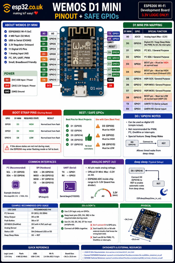
The Wemos/LOLIN D1 MiniAliExpress price is one of the easiest ESP8266AliExpress price boards to use because it combines a 4 MB ESP8266AliExpress price module, USB programming, 3.3 V regulation and breadboardAliExpress price-friendly headers in a very small board. For most projects, the best GPIOs are D1/GPIO5, D2/GPIO4, D5/GPIO14, D6/GPIO12 and D7/GPIO13. D3/GPIO0, D4/GPIO2 and D8/GPIO15 are boot-strapping pins and must be at the correct logic level while the ESP8266AliExpress price starts. D0/GPIO16 is safe for basic digital I/O but has special limitations and is normally connected to RST for timed deep-sleep wake-up. RX/GPIO3 and TX/GPIO1 can also be reused, but doing so interferes with serial communication. The current official LOLIN D1 Mini V4 uses USB-C, 4 MB flash and an A0 input rated up to approximately 3.2 V.
Materials You’ll Need
A basic D1 Mini project normally requires only a few inexpensive parts:
| Item | Why you need it |
|---|---|
| Wemos / LOLIN D1 Mini | Main ESP8266 development board |
| USB-C data cable | Programming and powering current V4 boards |
| Micro-USB data cable | Required by many older D1 Mini boards/clones |
| 2.54 mm header pins | Connect the board to a breadboard |
| Breadboard | Easy prototyping |
| Dupont jumper wires | Connecting sensors and modules |
| 3.3 V-compatible sensor | SHT40, BME280, DS18B20, etc. |
| 220–470 Ω resistors | Useful for LEDs |
| 4.7 kΩ resistor | Useful for DS18B20/OneWire |
| Multimeter | Useful for checking power and GPIO wiring |
For a first project, an SHT40, BME280 or DS18B20 is ideal because these sensors need very little additional hardware.
This materials section is also a convenient place to add product/affiliate links without interrupting the technical guide.
What is the Wemos D1 Mini?
The D1 Mini is a compact ESP8266 development board originally created by Wemos and now sold under the LOLIN brand.
Its popularity comes from combining nearly everything needed for ESP8266 development on one small PCB:
- ESP8266 Wi-Fi microcontroller
- 4 MB SPI flash
- USB-to-serial interface
- voltage regulator
- USB connector
- RESET circuitry
- automatic flashing circuitry
- onboard LED
- accessible ADC input
- breadboard-friendly GPIO headers
Unlike the ESP-01S, the D1 Mini exposes most of the useful ESP8266 GPIOs.
That makes it dramatically easier to use with:
- displays
- sensors
- relays
- buttons
- SPI modules
- I²C devices
- OneWire sensors
- deep sleep
The current official LOLIN D1 Mini V4.0.0 uses USB-C and measures approximately 34.2 × 25.6 mm.
Current D1 Mini specifications
| Feature | LOLIN D1 Mini |
|---|---|
| MCU | ESP8266EX |
| CPU | Tensilica L106 32-bit |
| Clock speed | 80 / 160 MHz |
| Wi-Fi | 802.11 b/g/n |
| Wi-Fi band | 2.4 GHz |
| Flash | 4 MB |
| Operating logic | 3.3 V |
| Digital I/O | 11 accessible GPIO functions |
| Analog inputs | 1 |
| A0 maximum | Approx. 3.2 V on official board |
| Current official USB | USB-C |
| PWM | Yes, except D0 limitation |
| I²C | Software-configurable |
| SPI | Yes |
| UART | Yes |
| OneWire | Yes |
| Bluetooth | No |
The D1 Mini is still based on the ESP8266, so it does not provide:
- Bluetooth
- Zigbee
- Thread
- Wi-Fi 6
- native USB
But for straightforward Wi-Fi IoT projects, it remains extremely capable.
The most confusing thing: D pins are not GPIO numbers
This is the single most important thing to understand about a D1 Mini.
The printed board labels:
D0
D1
D2
D3
...
do not directly match the ESP8266 GPIO numbers.
For example:
D1 = GPIO5and:
D5 = GPIO14This causes enormous confusion when combining:
- Arduino examples
- ESPHome YAML
- ESP8266 datasheets
- Wemos diagrams
- generic ESP8266 tutorials
The complete mapping is:
| D1 Mini label | ESP8266 GPIO | Main function |
|---|---|---|
| D0 | GPIO16 | Digital I/O / deep-sleep wake |
| D1 | GPIO5 | I²C SCL / general GPIO |
| D2 | GPIO4 | I²C SDA / general GPIO |
| D3 | GPIO0 | Boot-strapping GPIO |
| D4 | GPIO2 | Boot-strapping GPIO / onboard LED |
| D5 | GPIO14 | SPI SCK / general GPIO |
| D6 | GPIO12 | SPI MISO / general GPIO |
| D7 | GPIO13 | SPI MOSI / general GPIO |
| D8 | GPIO15 | SPI CS / boot-strapping GPIO |
| RX | GPIO3 | UART RX |
| TX | GPIO1 | UART TX |
| A0 | ADC0 | Analog input |
This table is worth bookmarking.
Quick safe GPIO cheat sheet
For most new projects, start with:
D1 = GPIO5
D2 = GPIO4
D5 = GPIO14
D6 = GPIO12
D7 = GPIO13
These are normally the easiest and least troublesome pins.
Best general-purpose GPIOs
D1 / GPIO5
D2 / GPIO4
D5 / GPIO14
D6 / GPIO12
D7 / GPIO13
These work well for:
- buttons
- sensors
- LEDs
- relays
- I²C
- SPI
- OneWire
- PWM
Safe, but with limitations
D0 / GPIO16
Useful for basic digital I/O and deep-sleep wake, but it behaves differently from the other ESP8266 GPIOs.
Use with care
D3 = GPIO0
D4 = GPIO2
D8 = GPIO15
These determine ESP8266 boot mode.
Serial pins
TX = GPIO1
RX = GPIO3
They can be reused after startup, but doing so interferes with UART logging/programming.
Safe GPIO reference table
| Pin | GPIO | Recommendation | Why |
|---|---|---|---|
| D0 | 16 | 🟡 Good with limitations | Special GPIO, deep-sleep wake |
| D1 | 5 | ✅ Excellent | Clean general GPIO / I²C |
| D2 | 4 | ✅ Excellent | Clean general GPIO / I²C |
| D3 | 0 | ⚠️ Use with care | Must be HIGH at normal boot |
| D4 | 2 | ⚠️ Use with care | Must be HIGH at boot, onboard LED |
| D5 | 14 | ✅ Excellent | Clean general GPIO / SPI |
| D6 | 12 | ✅ Excellent | Clean general GPIO / SPI |
| D7 | 13 | ✅ Excellent | Clean general GPIO / SPI |
| D8 | 15 | ⚠️ Use with care | Must be LOW at boot |
| RX | 3 | 🟡 Usable | UART0 RX |
| TX | 1 | ⚠️ Usable with care | UART0 TX + boot messages |
| A0 | ADC | ✅ Analog only | Approx. 3.2 V max on official D1 Mini |
Why D1, D2, D5, D6 and D7 are the best pins
These GPIOs do not determine the ESP8266’s boot mode.
That means attached hardware can generally be HIGH or LOW during reset without preventing the microcontroller from starting.
For example:
D1 → button
D2 → relay
D5 → temperature sensor
D6 → input
D7 → LED
will generally be much easier to design than connecting the same devices to D3, D4 or D8.
This is why these five pins should be considered the D1 Mini’s first-choice GPIO set.
ESP8266 boot pins
The ESP8266 uses three pins to determine how it starts:
GPIO0
GPIO2
GPIO15
On the D1 Mini these correspond to:
D3 = GPIO0
D4 = GPIO2
D8 = GPIO15
For normal boot from flash:
GPIO0  = HIGH
GPIO2  = HIGH
GPIO15 = LOW
The D1 Mini already includes the necessary pull-up/pull-down circuitry.
Problems occur when external hardware overrides those states.
Normal boot state
For normal operation:
| D1 Mini pin | GPIO | Required at reset |
|---|---|---|
| D3 | GPIO0 | HIGH |
| D4 | GPIO2 | HIGH |
| D8 | GPIO15 | LOW |
The easy rule is:
D3 HIGH
D4 HIGH
D8 LOW
during startup.
After boot, all three can be used as normal GPIOs.
D3 / GPIO0
D3 maps to:
GPIO0GPIO0 determines whether the ESP8266 starts normally or enters its serial bootloader.
GPIO0 HIGH during reset
Normal firmware bootGPIO0 LOW during reset
UART flashing modeThis is why D3 is risky for:
- normally-closed buttons
- relay modules
- devices with strong pull-downs
If connected hardware holds D3 LOW when the board resets, the application does not start.
Instead, the ESP8266 waits for new firmware.
Can D3 still be used?
Absolutely.
After startup, D3 is a normal GPIO.
Good applications include inputs where the external circuit naturally remains HIGH during startup.
For example:
#define BUTTON_PIN D3

void setup() {
  pinMode(BUTTON_PIN, INPUT_PULLUP);
}

void loop() {
  if (digitalRead(BUTTON_PIN) == LOW) {
    // Button pressed
  }
}
This works because the button only pulls GPIO0 LOW when pressed.
But if the user holds the button while powering up:
ESP8266 enters flashing modeThat may or may not be acceptable.
D4 / GPIO2
D4 maps to:
GPIO2For normal ESP8266 startup, GPIO2 must be HIGH.
D4 also commonly drives the D1 Mini’s onboard LED.
The LED is normally:
active LOW
which means:
D4 LOW
→ LED ON

D4 HIGH
→ LED OFF
This works conveniently with the required HIGH boot state because the LED stays OFF while the ESP8266 starts.
Blink the onboard LED
Arduino defines the board’s LED as:
LED_BUILTINA simple example is:
void setup() {
  pinMode(LED_BUILTIN, OUTPUT);
}

void loop() {
  digitalWrite(LED_BUILTIN, LOW);
  delay(500);

  digitalWrite(LED_BUILTIN, HIGH);
  delay(500);
}
Again:
LOW = ON
HIGH = OFF
because the onboard LED is active LOW.
D8 / GPIO15
D8 is:
GPIO15and is the opposite of D3/D4 at startup.
For normal boot:
GPIO15 must be LOWThe D1 Mini includes a pull-down resistor to keep it LOW.
A peripheral that strongly pulls D8 HIGH during reset can prevent normal startup.
This makes D8 a poor choice for some:
- relay boards
- active-HIGH enable inputs
- devices containing pull-up resistors
After startup, D8 works as a normal GPIO.
Why D8 is commonly used as SPI CS
D8 is also the ESP8266:
HSPI_CSpin.
SPI chip-select lines are often LOW or HIGH depending on application, so the boot requirement must still be considered.
The traditional D1 Mini SPI assignment is:
D5 → SCK
D6 → MISO
D7 → MOSI
D8 → CS
which makes wiring SPI devices very convenient.
D0 / GPIO16 is different
D0 maps to:
GPIO16This GPIO behaves differently from the normal ESP8266 GPIO group.
It can be used as:
- digital input
- digital output
- deep-sleep wake signal
but it has limitations.
The official Wemos documentation excludes D0 from the normal set supporting features such as:
- interrupts
- PWM
- I²C
- OneWire
So D0 should not be treated as equivalent to D1 or D2.
It is excellent for simple jobs such as:
LED
basic output
simple input
deep-sleep wake
but not the first choice for timing-sensitive protocols.
D0 and deep sleep
D0 is extremely useful because GPIO16 is the ESP8266’s deep-sleep wake output.
To wake automatically from deep sleep:
D0 / GPIO16
→ RST
must be connected.
Then the ESP8266 can enter deep sleep:
ESP.deepSleep(10 * 60 * 1000000ULL);for approximately ten minutes.
When the timer expires:
GPIO16 changes state
→ pulls RESET
→ ESP8266 restarts
This is why D1 Mini is much better for battery-powered ESP8266 projects than ESP-01S, where GPIO16 is not exposed.
Example deep-sleep wiring
Connect:
D0
│
└──── RST
Then use:
void setup() {
  // Connect Wi-Fi
  // Read sensor
  // Send data

  ESP.deepSleep(
    10ULL * 60ULL * 1000000ULL
  );
}

void loop() {
}
The ESP8266 starts again from setup() after waking.
D1 / GPIO5 and D2 / GPIO4
These are arguably the best two pins on the entire board.
The traditional I²C mapping is:
D1 / GPIO5 → SCL
D2 / GPIO4 → SDA
This has become such a strong convention that most D1 Mini tutorials and shields follow it.
Typical I²C devices include:
Arduino I²C example
#include <Wire.h>

void setup() {
  Wire.begin(D2, D1);
}

void loop() {
}
Remember the order:
Wire.begin(SDA, SCL);So:
D2 = SDA
D1 = SCL
ESPHome I²C example
i2c:
  sda: D2
  scl: D1
  scan: true
A sensor can then be added normally.
For example:
sensor:
  - platform: sht4x
    temperature:
      name: "Room Temperature"

    humidity:
      name: "Room Humidity"
This is one of the cleanest D1 Mini configurations.
D5, D6 and D7
These are another excellent group of GPIOs:
D5 = GPIO14
D6 = GPIO12
D7 = GPIO13
They also form the ESP8266’s hardware SPI bus:
D5 → SCK
D6 → MISO
D7 → MOSI
This makes them ideal for:
- TFT displays
- SD cards
- external ADCs
- SPI sensors
- radio modules
When SPI is not needed, all three can simply be used as normal GPIOs.
Traditional D1 Mini SPI pinout
| SPI function | D1 Mini |
|---|---|
| SCK | D5 / GPIO14 |
| MISO | D6 / GPIO12 |
| MOSI | D7 / GPIO13 |
| CS / SS | D8 / GPIO15 |
Example:
#include <SPI.h>

void setup() {
  SPI.begin();
}

void loop() {
}
On the ESP8266 Arduino core, the standard hardware SPI configuration automatically uses the normal HSPI pins.
RX and TX
The D1 Mini exposes the ESP8266’s main hardware UART.
TX = GPIO1
RX = GPIO3
These pins are used for:
- flashing
- Serial Monitor
- debugging
- serial peripherals
They can also become normal GPIOs after boot.
TX / GPIO1 warning
GPIO1 outputs serial boot/debug information during startup.
So if TX is reused as:
relay control
MOSFET gate
LED
enable signal
the connected hardware may receive unexpected pulses while the ESP8266 starts.
For this reason TX is normally one of the last pins to reuse.
RX / GPIO3
RX is somewhat easier to reuse.
GPIO3 does not have a boot-strapping function.
If the project does not need serial reception, it can become an extra GPIO.
For example:
pinMode(3, INPUT_PULLUP);But programming/debugging is simpler when RX/TX remain available.
A0 analog input
The D1 Mini exposes one analog input:
A0This is an important difference from the ESP-01.
The bare ESP8266 ADC itself only accepts approximately:
0–1.0 Vbut the official D1 Mini includes an onboard resistor divider.
Current LOLIN documentation specifies the board-level A0 input at approximately:
3.2 V maximumThis means the official D1 Mini can measure signals across roughly the normal 3.3 V logic range.
Important clone warning for A0
Not every board sold as a:
D1 Miniis an official LOLIN board.
Some clones may use:
- different divider values
- different regulators
- different USB chips
- slightly different ADC circuitry
If precise analog measurement matters, verify the actual board.
Never assume an unknown bare ESP8266 module accepts 3.3 V on its ADC just because a D1 Mini does.
Arduino analog example
void setup() {
  Serial.begin(115200);
}

void loop() {
  int value = analogRead(A0);

  Serial.println(value);

  delay(500);
}
The ESP8266 ADC provides a 10-bit digital result:
0–1023representing the measured analog input range.
Good uses for A0
A0 is useful for:
- potentiometers
- analog light sensors
- battery-voltage dividers
- analog pressure sensors
- soil sensors
- current-monitor outputs
For higher-resolution or multiple analog channels, use an external ADC such as:
ADS1115over I²C.
Power pins
The D1 Mini exposes:
5V
3V3
GND
5V
This rail is related to USB input power and the onboard regulator.
It can be used to power the board from an appropriate 5 V supply.
3V3
This is the regulated 3.3 V rail.
Use it for 3.3 V sensors and modules.
GND
Common ground.
All external modules must normally share ground with the D1 Mini.
GPIO logic is 3.3 V only
The board may accept 5 V power through its 5V/USB side, but the ESP8266 GPIO remains 3.3 V logic.
Do not connect:
5 V logic
→ D1 Mini GPIO
directly.
Use:
- voltage divider
- level shifter
- appropriate interface circuit
where required.
This distinction is critical:
5 V board power
≠
5 V GPIO tolerance
Recommended pins for a relay
The best relay-control pins are usually:
D1
D2
D5
D6
D7
For example:
#define RELAY_PIN D5

void setup() {
  pinMode(RELAY_PIN, OUTPUT);
  digitalWrite(RELAY_PIN, LOW);
}

void loop() {
}
Do not drive a bare relay coil directly from the ESP8266 GPIO.
Use:
- relay module
- transistor driver
- MOSFET driver
as appropriate.
Why boot pins can be troublesome with relays
Many inexpensive relay modules contain input resistors, optocouplers or transistor networks that impose a logic state on the ESP8266 pin.
Connecting one to:
D3
D4
D8
can therefore prevent boot.
A project that works until a relay is connected often has a boot-strapping conflict, not a software problem.
Use D1, D2, D5, D6 or D7 instead when possible.
Best pin for DS18B20
A good choice is:
D5 / GPIO14or:
D2 / GPIO4Typical wiring:
3.3V
  │
 4.7kΩ
  │
  ├──── DATA
  │
DS18B20
  │
 GND
Example using D5:
#define ONE_WIRE_BUS D5D5 has no boot-strapping complication and is therefore a particularly clean choice.
ESPHome DS18B20 example
Using D5:
one_wire:
  - platform: gpio
    pin: D5

sensor:
  - platform: dallas_temp
    name: "Temperature"
The 4.7 kΩ pull-up resistor should still be installed between the data line and 3.3 V.
Best pins for pushbuttons
Good button pins include:
D1
D2
D5
D6
D7
RX
Example:
#define BUTTON_PIN D6

void setup() {
  pinMode(BUTTON_PIN, INPUT_PULLUP);
}

void loop() {
  if (digitalRead(BUTTON_PIN) == LOW) {
    // Button pressed
  }
}
D3 can also be used with a button, but pressing it during reset may put the ESP8266 into programming mode.
Best pins for LEDs
For a normal external LED:
D1
D2
D5
D6
D7
are straightforward.
Example:
D5
 │
220Ω
 │
LED
 │
GND
Avoid using TX for an indicator connected to something sensitive because UART output occurs at boot.
Best pins for PWM
Good PWM outputs include:
D1
D2
D3
D4
D5
D6
D7
D8
provided boot requirements are respected.
D0/GPIO16 is the exception.
The official D1 Mini documentation specifically excludes D0 from the normal PWM-capable group.
So for PWM:
do not choose D0.
A good first choice is:
D5Fan or MOSFET control
For PWM fan or MOSFET applications:
D5
D6
D7
are excellent candidates.
For example:
#define PWM_PIN D5

void setup() {
  pinMode(PWM_PIN, OUTPUT);
}

void loop() {
  analogWrite(PWM_PIN, 512);
}
Use a proper transistor/MOSFET driver when controlling significant current.
Recommended pin recipes
I²C sensor
D1 → SCL
D2 → SDA
SPI display
D5 → SCK
D6 → MISO
D7 → MOSI
D8 → CS
Be aware of D8’s boot LOW requirement.
DS18B20
D5 → DATARelay
D6 → relay inputPushbutton
D7 → buttonAnalog sensor
A0 → analog outputDeep-sleep wake
D0 → RSTA very clean general-purpose allocation
For a Home Assistant sensor/relay node:
| Function | Recommended pin |
|---|---|
| I²C SCL | D1 |
| I²C SDA | D2 |
| Relay | D5 |
| Button | D6 |
| Extra input/output | D7 |
| Analog sensor | A0 |
| Deep-sleep wake | D0 → RST |
This avoids the boot-sensitive D3, D4 and D8 pins entirely.
Arduino D pin names vs raw GPIO numbers
The Arduino ESP8266 core allows:
pinMode(D1, OUTPUT);which is normally clearer than:
pinMode(5, OUTPUT);Both refer to:
GPIO5But ESPHome configurations may use either board aliases or raw GPIO numbers depending on platform/configuration.
When reading an ESP8266 datasheet, always translate:
GPIO5into:
D1for the D1 Mini.
Flashing the D1 Mini
Unlike ESP-01S, the D1 Mini normally handles firmware flashing automatically.
The onboard USB-to-UART circuitry can control the necessary:
- GPIO0
- RESET
signals.
In most cases:
Connect USB
↓
Select board/port
↓
Upload
is all that is required.
There is normally no need to manually ground GPIO0.
Manual flashing mode
If automatic flashing fails, the board can still be forced into serial download mode.
The important condition is:
GPIO0 / D3 LOW during resetOn boards with suitable buttons, holding FLASH while resetting performs this operation.
Some clone boards have different button layouts, so inspect the labels on the actual PCB.
Arduino IDE setup
Install the ESP8266 Arduino core, then choose a D1 Mini-compatible board.
Typical selection:
LOLIN(WEMOS) D1 R2 & minior the current corresponding D1 Mini entry in the ESP8266 board package.
Useful settings typically include:
CPU Frequency:
80 MHz

Flash Size:
4 MB
For ordinary IoT projects, there is little reason to change the CPU from 80 MHz unless the application requires additional processing performance.
80 MHz vs 160 MHz
The ESP8266 can run at:
80 MHzor:
160 MHzFor:
80 MHz is normally sufficient.
160 MHz may help with:
- heavier processing
- complex web interfaces
- signal processing
- time-sensitive workloads
but can increase power consumption.
ESPHome setup
A simple D1 Mini configuration looks like:
esphome:
  name: d1-mini
  friendly_name: D1 Mini

esp8266:
  board: d1_mini

logger:

api:

ota:

wifi:
  ssid: !secret wifi_ssid
  password: !secret wifi_password
Then normal ESPHome components can use the D pins.
For example:
switch:
  - platform: gpio
    pin: D5
    name: "Relay"
Why D1 Mini remains good for ESPHome
A D1 Mini offers:
- 4 MB flash
- enough RAM for many modest ESPHome configurations
- Wi-Fi
- plenty of GPIOs
- ADC
- USB programming
- tiny physical size
That still makes it excellent for:
- temperature sensors
- relays
- garage-door controllers
- energy pulse counters
- weather sensors
- MQTT nodes
The main limitation is that the ESP8266 platform is much more memory-constrained than modern ESP32 chips.
When ESP32 is the better choice
Use a newer ESP32 if the project needs:
- Bluetooth
- BLE proxy
- Zigbee
- Thread
- Matter
- many ADC channels
- more RAM
- USB
- more GPIO
- complex ESPHome configurations
- mmWave + multiple sensors + displays
- modern security/peripherals
A D1 Mini does not become bad simply because newer chips exist.
It remains excellent when its capabilities match the project.
D1 Mini vs ESP-01S
Both use the ESP8266, but the experience is completely different.
ESP-01S
Provides:
- tiny module
- two easy application GPIOs
- no USB
- no exposed ADC
- awkward flashing
- usually 1 MB flash
D1 Mini
Provides:
- USB programming
- 4 MB flash
- many exposed GPIOs
- A0 analog input
- GPIO16 for deep sleep
- breadboard-friendly headers
For experimenting and prototyping:
D1 Mini wins easily.
ESP-01S makes more sense when physical size or an existing 8-pin socket matters.
D1 Mini vs NodeMCU
Both are ESP8266 development boards.
The NodeMCU is physically larger and exposes similar ESP8266 functionality.
The D1 Mini is:
- smaller
- easier to embed
- compatible with the D1 Mini shield ecosystem
- still breadboard friendly
For most compact projects:
D1 Mini is preferable.
NodeMCU can still be easier when a physically larger development board is not a problem.
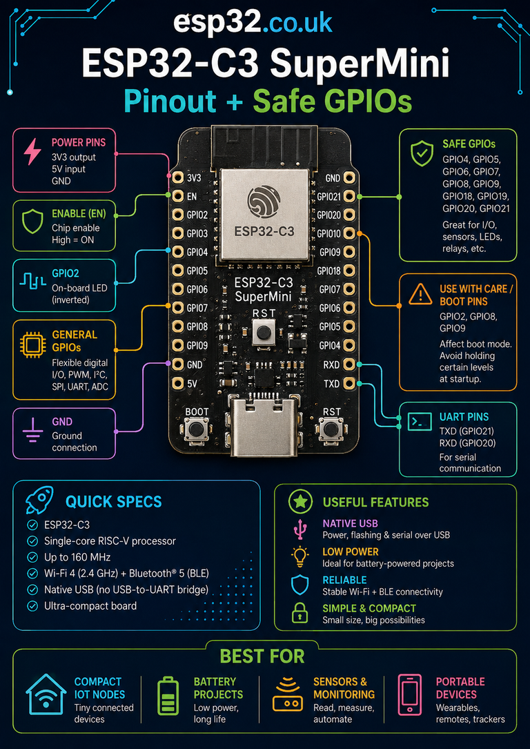
D1 Mini vs ESP32-C3 SuperMini
For a completely new project, the ESP32-C3 has several advantages:
- RISC-V CPU
- more RAM
- Bluetooth LE
- native USB
- newer security
- newer peripherals
But the D1 Mini still has:
- a huge library/tutorial ecosystem
- a mature board design
- simple pin layout
- a vast shield ecosystem
- very cheap hardware
- excellent ESPHome support
Existing D1 Mini projects do not need replacing merely because the C3 exists.
D1 Mini shields
One unusual strength of the Wemos ecosystem is its stackable shield system.
D1 Mini shields have been produced for:
- OLED displays
- relays
- batteries
- motor drivers
- temperature sensors
- microSD
- RTC
- prototyping
- DC power
- RGB LEDs
Because the header layout remained consistent for years, many older shields still work with newer boards.
This makes the D1 Mini more than just an ESP8266 breakout.
It is effectively a small modular development ecosystem.
Common problem: board won’t boot
First disconnect anything connected to:
D3
D4
D8
Then reset.
If the board now boots, a peripheral was probably forcing one of the ESP8266 strapping pins into the wrong state.
Remember:
D3 HIGH
D4 HIGH
D8 LOW
at startup.
Common problem: relay prevents booting
Move the relay from:
D3 / D4 / D8to:
D1 / D2 / D5 / D6 / D7if possible.
Some relay inputs contain pull-up or pull-down circuitry that conflicts with the ESP8266’s required boot state.
This is one of the most common D1 Mini wiring problems.
Common problem: onboard LED appears backwards
That is normal.
The onboard LED on D4/GPIO2 is typically active LOW:
LOW = ON
HIGH = OFF
So:
digitalWrite(LED_BUILTIN, LOW);turns it on.
Common problem: A0 readings are wrong
Check:
- sensor voltage range
- clone-board divider
- ground connection
- ADC scaling
- power-supply noise
Also remember that the bare ESP8266 ADC is not the same thing as the D1 Mini A0 header.
The official D1 Mini adds its own voltage divider.
Common problem: deep sleep never wakes
Check whether:
D0is physically connected to:
RSTThe software timer alone is not enough.
The GPIO16 wake pulse must reach the ESP8266 reset input.
Common problem: D0 doesn’t support an interrupt
That is expected.
GPIO16/D0 is connected differently internally from the main ESP8266 GPIO bank.
Use:
D1
D2
D5
D6
D7
for an interrupt-driven input instead.
Common problem: Serial output makes an attached device move
If that device is connected to:
TX / GPIO1the ESP8266’s startup messages are probably driving it.
Move the device to another GPIO or design the external interface so boot UART output cannot activate it.
Common problem: cheap clone won’t upload
Check:
- USB cable supports data
- USB serial driver
- correct COM port
- correct board selection
- FLASH/RESET buttons if present
- 3.3 V regulator stability
Older boards often use CH340-family USB-UART chips and may require the appropriate computer driver.
Wemos vs LOLIN naming
Many people still call the board:
Wemos D1 Mini
because that is how it became famous.
The current official branding is generally:
LOLIN D1 mini
under Wemos’ documentation ecosystem.
Search queries and marketplace listings still commonly use:
- Wemos D1 Mini
- WeMos D1 Mini
- LOLIN D1 Mini
- D1 Mini ESP8266
They normally refer to the same board family.
Current V4 vs older D1 Mini versions
The official board has evolved over time.
Current documentation lists:
V4.0.0
as the current revision.
One obvious difference is:
Current V4
USB-COlder boards
commonly use:
Micro-USBThe current board also includes a small LOLIN I²C connector.
Many marketplace boards are clones of older versions, so a product labelled “D1 Mini” may not look exactly like the current official V4 board.
The core D-pin mapping, however, has remained the important compatibility layer.
Best pins to remember
If only one part of this guide is remembered, use this:
Best general-purpose pins
D1 = GPIO5
D2 = GPIO4
D5 = GPIO14
D6 = GPIO12
D7 = GPIO13
Special but useful
D0 = GPIO16Boot-sensitive
D3 = GPIO0  → HIGH at boot
D4 = GPIO2  → HIGH at boot
D8 = GPIO15 → LOW at boot
UART
TX = GPIO1
RX = GPIO3
Analog
A0Deep-sleep wake
D0 → RSTThat small set of rules prevents most D1 Mini GPIO problems.
Related ESP8266 & ESP32 Guides
Useful internal links for this page include:
- ESP-01 / ESP-01S Pinout + GPIO, Boot Pins & Flashing
- ESP8266 Versions and Development Boards Compared
- ESP8266 Survival Guide
- ESP32 vs ESP8266: Which Should You Use?
- ESP32-C3 SuperMini Pinout + Safe GPIOs
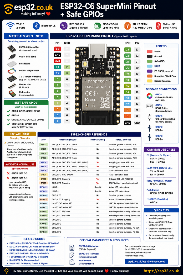
- ESP32-C6 SuperMini Pinout + Safe GPIOs
- ESP32 Arduino Blink Explained for Complete Beginners
- ESP32 Pushbutton Example Explained
- ESP32 Deep Sleep Battery Sensors
These should link to the corresponding esp32.co.uk articles to keep visitors inside the ESP8266/ESP32 beginner and pinout clusters.
Final recommendation
The Wemos/LOLIN D1 Mini remains one of the best ways to use an ESP8266.
Its most useful pins are:
D1
D2
D5
D6
D7
because they avoid the ESP8266’s boot-strapping requirements.
Use:
D3
D4
D8
only after understanding that:
D3 HIGH
D4 HIGH
D8 LOW
must be maintained during reset.
Use:
D0for simple digital I/O or its particularly useful:
deep sleep → RSTfunction.
The board may be old compared with the latest ESP32-C5/C6/S3 families, but for a project requiring:
Wi-Fi + several GPIOs + low cost + simple Arduino/ESPHome support
the D1 Mini still performs extremely well.
For new projects that need Bluetooth, Zigbee, Thread or substantially more memory, move to an ESP32.
For straightforward ESP8266 Wi-Fi sensors and controllers, the D1 Mini remains one of the easiest boards ever made.
Metadata
SEO title:
Wemos D1 Mini Pinout + Safe GPIOs
Datasheets & External Resources
All manufacturer and technical documentation is collected here rather than linked throughout the article.
Official LOLIN D1 Mini Documentation — current V4 specifications, pinout, 4 MB flash, USB-C, board dimensions and A0 rating. (docs.wemos.cc)
LOLIN D1 Mini Documentation
Espressif ESP8266EX Datasheet — official ESP8266 GPIO, ADC, UART, boot and electrical specifications. (Espressif Documentation)
ESP8266EX Datasheet
Espressif ESP8266 Technical Reference Manual — detailed GPIO and peripheral documentation. (Espressif Documentation)
ESP8266 Technical Reference Manual
Espressif ESP8266 Boot Mode Selection — official explanation of GPIO0, GPIO2 and GPIO15 boot-strapping requirements. (Espressif Systems)
ESP8266 Boot Mode Selection