Quick Summary (TL;DR):
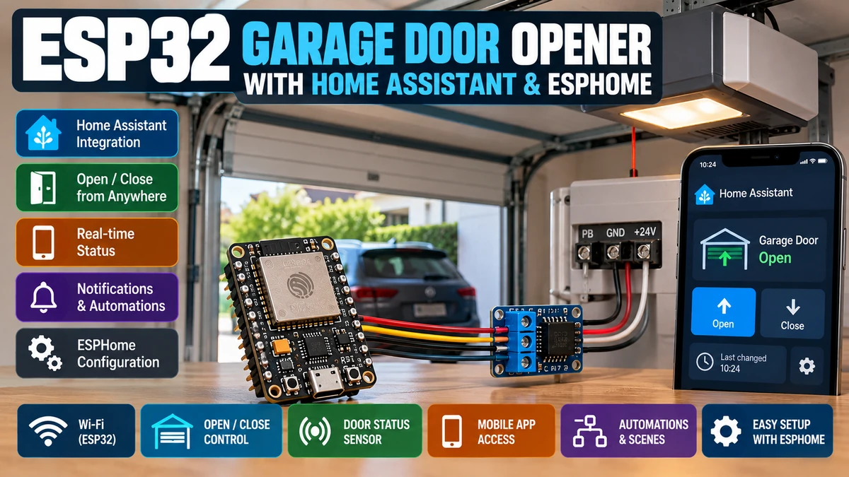
The safest and most universal way to add an ESP32AliExpress price garage door opener to Home Assistant is to imitate the existing wall pushbuttonAliExpress price rather than trying to control the motor directly. Use a dry-contact relay connected across the opener’s low-voltage pushbutton terminals, pulse that relay for about 300–700 ms, and add at least one magnetic reed switchAliExpress price so the ESP32AliExpress price knows whether the door is physically closed. ESPHome can then expose a proper garage cover entity to Home Assistant instead of a raw relay switch. The relay should always boot OFF, should never remain energised, and should not bypass the opener’s photo-eyes, force sensing, obstruction detection or mechanical limits. A single closed-position reed switchAliExpress price is enough for a reliable “closed vs not closed” retrofit; adding a second fully-open sensor gives much better state information. For a typical one-button garage opener, open, close and stop are all produced by the same momentary relay pulse, so ESPHome must avoid issuing unnecessary pulses when the door is already in the requested end state. This guide uses the current ESPHome cover model and Home Assistant garage device class, and keeps all control local through the ESPHome native API.
Materials You’ll Need
| Item | Why you need it |
|---|---|
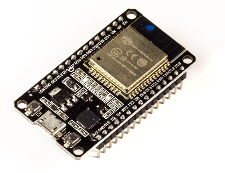
| ESP32 development board | Runs ESPHome and connects locally to Home Assistant |
| 1-channel dry-contact relay module | Momentarily shorts the opener’s wall-button terminals |
| Magnetic reed switch + magnet | Detects the fully-closed door position |
| Optional second reed switch | Detects fully-open position |
| 5 V USB power supply or suitable buck converter | Powers the ESP32 reliably |
| Low-voltage hookup wire | Relay/button/reed-switch wiring |
| Small enclosure | Protects ESP32 and low-voltage wiring |
| Multimeter | Confirms wall-button terminals and relay contact behaviour |
| Home Assistant + ESPHome | Local control, state, automations and notifications |
Choose the relay carefully. The useful part is the relay’s COM/NO dry contacts. Do not use a module whose output is a switched 5 V/12 V/230 V feed when the opener expects only a passive pushbutton contact.
How a Traditional Garage Door Wall Button Works
Many garage-door operators have two low-voltage terminals for a simple pushbutton. Pressing the wall button briefly closes the circuit between those terminals.
Garage opener button terminals
       ┌──────────── wall button ────────────┐
       │                                     │
Terminal A                                 Terminal B

Button pressed → A and B momentarily shorted
A relay can sit in parallel with that wall button. When the ESP32 energises the relay for half a second, the opener sees exactly the same electrical event as a physical button press.
Original wall button ─────┐
                          ├── opener button terminals
ESP32 dry-contact relay ──┘
Why a Dry-Contact Relay Is the Right Interface
A dry contact is electrically isolated from the ESP32 control side. The relay contacts do not inject the ESP32’s 3.3 V or 5 V into the garage opener; they simply open or close like a mechanical switch.
- Preserves the opener’s existing wall-button logic
- Works with many different low-voltage control circuits
- Provides galvanic separation between ESP32 logic and opener input
- Keeps the original wall button functional
- Makes the ESP32 easy to remove without changing the opener itself
This is very different from connecting an ESP32 GPIO directly across the opener terminals. The voltage, polarity and signalling used by those terminals may not be compatible with a 3.3 V microcontroller.
Important: Some Modern Wall Controls Are Not Simple Contacts
Not every opener uses a plain normally-open pushbutton. Some newer wall consoles communicate digitally over the same two wires and may include lighting, lock or menu functions.
Before wiring the relay, confirm that briefly shorting the intended terminals is a valid command for your specific opener. The easiest safe test is usually to inspect the manufacturer wiring diagram or measure/trace the simple pushbutton input. Do not experiment by shorting random terminals.
What the ESP32 Should NOT Control
- Motor mains supply
- Motor direction wiring
- Photo-eye / safety-beam circuit
- Force/obstruction sensing
- Mechanical limit switches inside the opener
- Emergency release mechanism
The existing garage opener should continue to perform all safety-critical motor control. The ESP32 should behave like an additional wall button plus a position monitor.
Why You Need a Door-Position Sensor
A relay alone tells you only that the ESP32 asked the opener to move. It does not tell you whether the door actually moved, stopped halfway, hit an obstacle or was operated by another remote.
Relay only:
ESP32 → command sent
ESP32 → no idea where the door really is

Relay + reed switch:
ESP32 → command sent
reed switch → physical door state confirmed
For Home Assistant, physical feedback is the difference between a useful garage-door entity and an optimistic remote-control button.
One Reed Switch vs Two
| Sensor setup | What you know | Practical result |
|---|---|---|
| One closed-position reed | Closed vs not closed | Simple and reliable retrofit; “not closed” may mean partly or fully open |
| Closed + open reeds | Fully closed / fully open / neither | Much better status; “neither” means intermediate position |
| No position sensor | Nothing physical | Optimistic only — not recommended for remote garage control |
For most installations, one closed sensor gives excellent value because the most important safety/security question is usually: is the garage definitely closed?
Where to Mount the Closed Reed Switch
Mount the magnet on the moving door and the reed switch on the fixed frame or rail so they align only when the door is fully closed.
- Keep the switch away from places where the door flexes or hits it.
- Use a robust wired magnetic contact intended for doors if possible.
- Test the detection gap before permanent mounting.
- Secure the wire so door movement cannot pull or crush it.
- Use a normally-closed or normally-open contact according to your preferred fail behaviour and configure ESPHome accordingly.
A long cable run from the reed switch is usually fine for a digital GPIO when it is wired sensibly and debounced. For very noisy environments, use stronger pull resistors, shield/twisted wiring or an opto-isolated input module.
Recommended ESP32 GPIOs
On a classic ESP32 DevKit, simple choices are:
GPIO26 → relay control
GPIO27 → closed reed switch
GPIO25 → optional open reed switch
These are examples, not mandatory pins. Avoid boot-strapping pins for the relay when possible, because a boot-time glitch on the relay output could trigger the garage door unexpectedly.
Relay Wiring
| Relay terminal | Connection |
|---|---|
| COM | Garage opener wall-button terminal A |
| NO | Garage opener wall-button terminal B |
| NC | Leave unused |
| VCC | Relay module supply as required by module |
| GND | ESP32/relay low-voltage ground if module requires it |
| IN | ESP32 relay GPIO |
Use the normally-open (NO) contact so the relay behaves exactly like an unpressed wall button when the ESP32 is powered off or rebooting.
Why Normally Open Is Safer
If the ESP32 loses power, a normally-open relay returns to an open circuit. The garage opener sees no button press.
ESP32 OFF → relay de-energised → COM/NO open → no commandUsing NC would create the opposite behaviour and could hold the wall-button circuit closed whenever the ESP32/relay is unpowered. That is not what you want.
Relay Pulse Duration
Most wall buttons need only a brief contact. A pulse of approximately 300–700 ms is a sensible starting range; 500 ms is common.
Relay ON
wait 500 ms
Relay OFF
Do not leave the relay permanently on. Some operators ignore a held button; others may interpret it differently. A momentary pulse most closely imitates normal manual operation.
ESPHome Relay Configuration
switch:
  - platform: gpio
    pin: GPIO26
    id: garage_relay
    internal: true
    restore_mode: ALWAYS_OFF

    on_turn_on:
      - delay: 500ms
      - switch.turn_off: garage_relay
restore_mode: ALWAYS_OFF is particularly important. Current ESPHome switch behaviour uses ALWAYS_OFF as the safe default, but declaring it explicitly documents the intent: an ESP32 reboot must never restore the relay in the ON state.
The relay is marked internal: true because Home Assistant should control the garage through a cover entity, not expose a raw switch that a user could accidentally leave or toggle without state logic.
Reed-Switch Wiring
A common simple circuit connects the reed switch between GPIO27 and GND while enabling the ESP32’s internal pull-up.
3.3 V
  │ internal pull-up
GPIO27 ───── reed switch ───── GND
When the magnet closes the reed contact, GPIO27 is pulled LOW. ESPHome can invert that electrical state so the logical binary sensor reports ON when the door is closed.
ESPHome Closed-Position Sensor
binary_sensor:
  - platform: gpio
    id: garage_closed
    name: "Garage Door Closed"
    device_class: garage_door
    pin:
      number: GPIO27
      mode:
        input: true
        pullup: true
      inverted: true
    filters:
      - delayed_on_off: 50ms
The small debounce filter prevents mechanical contact bounce or wiring noise from creating rapid open/closed events. ESPHome’s current binary-sensor guidance explicitly recommends debounce filtering for physical switches.
Simple One-Sensor ESPHome Garage Cover
For a one-button opener with one closed reed switch, the most useful Home Assistant model is:
reed ON  → CLOSED
reed OFF → OPEN / not fully closed
That second state is deliberately broad. With only one switch, the ESP32 cannot distinguish fully open from half-open.
cover:
  - platform: template
    name: "Garage Door"
    id: garage_door
    device_class: garage

    lambda: |-
      if (id(garage_closed).state) {
        return COVER_CLOSED;
      } else {
        return COVER_OPEN;
      }

    open_action:
      - if:
          condition:
            binary_sensor.is_on: garage_closed
          then:
            - switch.turn_on: garage_relay

    close_action:
      - if:
          condition:
            binary_sensor.is_off: garage_closed
          then:
            - switch.turn_on: garage_relay

    stop_action:
      - switch.turn_on: garage_relay
The conditions matter because many garage operators use a single toggle input. If the door is already open and Home Assistant sends OPEN again, another relay pulse could make the opener close instead. The state check prevents that unnecessary command at the known closed end state.
The Limitation of a One-Button Toggle Opener
Most simple wall-button garage openers operate as a sequence similar to:
Closed → pulse → Opening
Opening → pulse → Stop
Stopped → pulse → Closing
Closing → pulse → Stop / reverse (model dependent)
The exact sequence depends on the opener. This is why a generic ESP32 cannot guarantee “OPEN means open” unless it knows enough about the current physical state and the opener’s behaviour.
With only a closed reed switch, issuing CLOSE while the door is not closed assumes the opener is in a state where the next button pulse will close. That is generally fine for a normal fully-open door, but less deterministic if the door is stopped halfway.
Better Design: Add a Fully-Open Reed Switch
A second reed switch removes much of that ambiguity. The ESP32 can distinguish:
closed sensor ON, open sensor OFF → fully CLOSED
closed sensor OFF, open sensor ON → fully OPEN
both OFF → somewhere between the endpoints
both ON → wiring/configuration fault
ESPHome Two-Sensor Inputs
binary_sensor:
  - platform: gpio
    id: garage_closed
    name: "Garage Door Closed"
    pin:
      number: GPIO27
      mode:
        input: true
        pullup: true
      inverted: true
    filters:
      - delayed_on_off: 50ms

  - platform: gpio
    id: garage_open
    name: "Garage Door Fully Open"
    pin:
      number: GPIO25
      mode:
        input: true
        pullup: true
      inverted: true
    filters:
      - delayed_on_off: 50ms
Two-Sensor Template State
cover:
  - platform: template
    name: "Garage Door"
    id: garage_door
    device_class: garage

    lambda: |-
      if (id(garage_closed).state) {
        return COVER_CLOSED;
      }
      if (id(garage_open).state) {
        return COVER_OPEN;
      }
      return {};
Returning {} tells the template cover to retain the last published state while neither end sensor is active. For truly accurate opening/closing movement state, add direction/timing logic or use a feedback-capable cover architecture.
Why ESPHome’s Feedback Cover Is Interesting
ESPHome also has a feedback cover platform designed for covers with endstop and/or movement feedback. It can combine open/closed end sensors with known movement times and can approximate intermediate position.
However, it is most natural when ESPHome has separate open and close actions or richer movement feedback. A traditional garage opener with one toggle button is unusual because the same relay pulse means open, close or stop depending on the opener’s internal state.
For that common retrofit, a template cover plus real end sensors is often easier to reason about than pretending the ESP32 directly controls motor direction.
When Endstop/Feedback Cover Makes More Sense
- The controller has separate OPEN and CLOSE inputs.
- The opener exposes reliable open/close movement signals.
- You are controlling a DIY motor/actuator with separate direction relays.
- You need approximate percentage position.
- You have both endstops and known travel times.
ESPHome’s current feedback cover can use endstop and movement sensors and supports maximum-duration safety limits. Do not use that architecture simply because it sounds more advanced; use it when the hardware actually exposes the required signals.
Full Basic ESPHome Configuration
esphome:
  name: garage-door
  friendly_name: Garage Door

esp32:
  board: esp32dev
  framework:
    type: esp-idf

logger:

api:
  encryption:
    key: !secret garage_api_key

ota:
  - platform: esphome
    password: !secret ota_password

wifi:
  ssid: !secret wifi_ssid
  password: !secret wifi_password
  ap:
    ssid: "Garage Door Fallback"
    password: !secret fallback_password

captive_portal:

switch:
  - platform: gpio
    pin: GPIO26
    id: garage_relay
    internal: true
    restore_mode: ALWAYS_OFF
    on_turn_on:
      - delay: 500ms
      - switch.turn_off: garage_relay

binary_sensor:
  - platform: gpio
    id: garage_closed
    name: "Garage Door Closed"
    pin:
      number: GPIO27
      mode:
        input: true
        pullup: true
      inverted: true
    filters:
      - delayed_on_off: 50ms

cover:
  - platform: template
    name: "Garage Door"
    id: garage_door
    device_class: garage

    lambda: |-
      if (id(garage_closed).state) {
        return COVER_CLOSED;
      } else {
        return COVER_OPEN;
      }

    open_action:
      - if:
          condition:
            binary_sensor.is_on: garage_closed
          then:
            - switch.turn_on: garage_relay

    close_action:
      - if:
          condition:
            binary_sensor.is_off: garage_closed
          then:
            - switch.turn_on: garage_relay

    stop_action:
      - switch.turn_on: garage_relay
Why Use a Cover Entity Instead of a Switch?
Home Assistant has a dedicated cover entity model for doors, blinds, shutters and garage doors. With device_class: garage, Home Assistant presents garage-specific controls and state instead of a generic ON/OFF switch.
That also makes automations more natural:
cover.open_cover
cover.close_cover
cover.stop_cover
The physical relay remains hidden as an implementation detail.
Home Assistant States
A garage cover can be represented as open, opening, closed, closing, unavailable or unknown depending on the information supplied by the integration.
A one-reed template configuration can reliably report closed versus not closed, but it cannot magically know movement direction. Do not add fake precision to the UI unless you have the sensors or timing logic to support it.
Door-Open Alert
One of the most useful automations is not remote opening at all — it is being warned when the door has been left open.
alias: Garage door left open
trigger:
  - platform: state
    entity_id: cover.garage_door
    to: "open"
    for: "00:10:00"

action:
  - service: notify.mobile_app_phone
    data:
      title: "Garage Door"
      message: "The garage door has been open for 10 minutes."
This is far safer than immediately auto-closing the door simply because a timer expired.
Should Home Assistant Automatically Close the Garage?
It can, but automatic closing deserves more caution than automatic lighting or HVAC.
Before allowing an unattended close command, verify that the original opener’s obstruction/photo-eye system is working correctly and that the area can be observed or otherwise protected. Never bypass the factory safety sensors in order to make remote automation work.
A good first automation is notify first. Add automatic closing only after you are comfortable with the system behaviour.
Presence / Occupancy Interlocks
Home Assistant can add extra software conditions, but these should be considered convenience layers rather than replacements for the opener’s certified safety functions.
- Do not auto-close while a garage motion sensor is active.
- Do not auto-close if a vehicle-presence sensor reports an unexpected condition.
- Require the factory photo-eye to remain functional.
- Send a warning notification before unattended close actions.
- Avoid auto-closing when Home Assistant state is unknown/unavailable.
A software sensor can fail. The opener’s own obstruction system remains the primary safety mechanism.
A Useful Security Automation
alias: Garage open at night
trigger:
  - platform: state
    entity_id: cover.garage_door
    to: "open"
    for: "00:05:00"

condition:
  - condition: time
    after: "22:30:00"
    before: "06:30:00"

action:
  - service: notify.mobile_app_phone
    data:
      title: "Garage warning"
      message: "The garage door is open."
Do Not Expose the ESP32 Directly to the Internet
Keep the ESP32 on the local network and let Home Assistant provide authenticated remote access. Do not port-forward ESPHome, a raw web server or MQTT broker to the public internet just to open the garage from a phone.
The native ESPHome API supports encrypted communication, and Home Assistant can handle user authentication and remote-access policy centrally.
ESPHome API Encryption
api:
  encryption:
    key: !secret garage_api_key
For a device controlling physical access to a property, enabling API encryption is a sensible default.
Wi-Fi Reliability
A garage often has weaker Wi-Fi than the centre of the house. Before permanently installing the ESP32 inside a metal opener housing, test RSSI and connection reliability.
- Mount the ESP32 outside large metal enclosures where possible.
- Use an ESP32 board/module with an external antenna if signal is poor.
- Keep the antenna end clear of metal and relay wiring.
- Avoid placing the ESP32 directly beside the motor or mains transformer.
- Use a stable power supply rather than relying on an unknown accessory rail.
A garage controller that works 95% of the time is not a good garage controller. Position feedback and stable networking matter more than fancy UI.
Powering the ESP32 from the Garage Opener
Some garage operators expose an accessory supply, but the voltage can be 12 V, 24 V or another level and may not be regulated for electronics.
If you use an accessory supply, verify voltage/current and use an appropriate buck converter to 5 V for the ESP32. Otherwise, a separate quality USB power supply is simpler.
Do not connect a nominal 12/24 V accessory output directly to the ESP32 VIN/5 V pin unless the board is explicitly designed for it.
Relay Module Gotcha: Active-Low Inputs
Many inexpensive relay boards are active LOW: pulling the input LOW energises the relay.
That can create a boot-time risk if the chosen GPIO floats or has an unfortunate startup level. Prefer a relay/module whose default state is known OFF, use a safe GPIO, and test several power cycles before connecting the contacts to the opener.
If the module requires inversion, configure the GPIO pin as inverted in ESPHome rather than relying on confusing logic elsewhere.
Boot Test Before Connecting the Opener
- Disconnect COM/NO from the garage opener.
- Power-cycle the ESP32 repeatedly.
- Listen/watch for relay clicks.
- Reboot via ESPHome.
- Perform OTA updates.
- Disconnect/reconnect Wi-Fi.
- Confirm the relay never pulses unexpectedly.
Only after that test should the dry contacts be connected to the opener’s button input.
How to Test the Wall-Button Input
With the opener documentation in hand, identify the two terminals used by the existing momentary wall button. A dry-contact relay placed in parallel should reproduce a normal press without disconnecting the original switch.
Do not short unknown terminals “to see what happens.” Some terminals supply accessories, safety sensors or bus communications.
Common Problem: Relay Clicks but Door Does Nothing
- Wrong opener terminals
- Wall control is digital/proprietary rather than dry-contact
- Relay wired COM/NC instead of COM/NO
- Pulse is too short
- Loose low-voltage wiring
- Opener lock/vacation mode active
First test continuity across COM/NO with a multimeter while the relay is activated. The contacts should close for the configured pulse duration.
Common Problem: Door Moves When ESP32 Reboots
Treat this as a serious configuration/hardware issue.
- Use
restore_mode: ALWAYS_OFF. - Use NO relay contacts.
- Choose a GPIO that does not glitch during boot.
- Check whether the relay board is active-low.
- Add an appropriate hardware pull resistor if needed.
- Consider a relay interface specifically designed for microcontroller-safe power-up behaviour.
Do not accept “it only happens occasionally.” A garage relay must remain inactive through boot, brownouts and firmware updates.
Common Problem: Door State Is Backwards
The reed sensor’s electrical logic may be inverted relative to the YAML.
If the binary sensor shows ON when the magnet is away rather than when the door is closed, change the inverted: setting or wiring scheme. Verify the binary sensor entity itself before debugging the cover.
Common Problem: Door State Flickers
Mechanical reed contacts can bounce and long wires can pick up noise. Use a small debounce such as:
filters:
  - delayed_on_off: 50ms
If flicker remains, inspect the physical magnet alignment and wiring before increasing the filter to several seconds.
Common Problem: Home Assistant Says Open While Door Is Halfway
That is expected with the simple one-closed-sensor model. “Open” really means not confirmed closed.
Add a second open reed switch or movement feedback if you need to distinguish fully open from intermediate positions.
Common Problem: Pressing Close Makes Door Open
This is the classic limitation of a one-button toggle opener. If the physical state and the opener’s internal command state are not aligned, the next pulse may not produce the direction Home Assistant expected.
Use real end-state sensors and avoid commands when the state is uncertain. If the opener provides dedicated OPEN/CLOSE contacts or a supported digital bus, integrate those instead of the generic toggle input.
Dedicated OPEN and CLOSE Inputs Are Better
Some openers expose separate terminals for OPEN, CLOSE and STOP. That is much easier to automate safely because commands are explicit rather than toggle-based.
Relay 1 → OPEN input
Relay 2 → CLOSE input
Relay 3 → STOP input
If your opener supports that arrangement, ESPHome’s feedback/endstop cover platforms become more natural and direction is much less ambiguous.
What About Manufacturer Bus Integrations?
Some garage-door families expose richer digital interfaces. Current ESPHome includes dedicated cover support for certain systems, including Hörmann HCP and Tormatic/Novoferm integrations.
A native bus integration can report real position, movement, lamp state and other information that a simple relay cannot know. If your opener is directly supported, that may be superior to the generic dry-contact retrofit.
But proprietary bus voltages/protocols must be interfaced correctly. For example, some Tormatic/Novoferm ports use 5 V UART signalling, which should not be connected directly to 3.3 V ESP GPIOs.
Dry-Contact Retrofit vs Native Bus
| Feature | Dry-contact relay | Supported native bus |
|---|---|---|
| Compatibility | Very broad | Model-specific |
| Installation complexity | Low | Medium |
| Door command | Simulates button press | Explicit protocol commands possible |
| State feedback | Needs reed sensors | Often reported by opener |
| Position percentage | Usually no | Sometimes yes |
| Lighting/extra functions | Usually no | Often possible |
| Best use | Universal retrofit | Supported opener with documented bus |
Reed Switch Failure Behaviour
Think about what happens if the sensor wire breaks.
With the common pull-up arrangement shown in this guide, an open/broken circuit reads as “not closed.” That is generally a useful fail-safe bias for security: Home Assistant is more likely to warn that the door is open than falsely report it as closed.
The exact fail behaviour depends on whether your reed is NO or NC and how you invert it. Test a disconnected wire deliberately so you know what Home Assistant will report.
Add a Sensor-Fault Check with Two Reeds
With separate OPEN and CLOSED sensors, both being active simultaneously is physically impossible in a normal installation and can be treated as a fault.
closed=ON + open=ON → sensor/wiring faultThat is one advantage of using two end sensors: the system can detect some wiring/configuration errors rather than silently trusting one contact.
Should You Use a Relay Board or Optocoupler/Transistor?
For a simple pushbutton input, a relay is attractive because its contact isolation makes the opener side electrically simple and easy to reason about.
An optocoupler or transistor can also imitate a contact in some circuits, but only after you understand voltage, polarity and current. A dry-contact relay is more universal for a guide intended to work across many opener brands.
Home Assistant Dashboard
Once imported through the ESPHome native API, the device appears as a garage cover. A dashboard can show:
- Garage Door cover entity
- Closed reed binary sensor
- Optional fully-open sensor
- Wi-Fi signal strength
- ESP32 uptime
- Last opened/closed time via Home Assistant helpers/automations
Keep the raw relay hidden. The user-facing control should always be the cover entity.
Recommended Automations
| Automation | Recommendation |
|---|---|
| Door left open notification | Highly recommended |
| Open at unexpected time notification | Recommended |
| Automatic close after timer | Use cautiously; notification-first is safer |
| Close when everyone leaves | Use only with reliable physical state and factory obstruction protection |
| Turn garage lights on when door opens | Low-risk and useful |
| Pause HVAC/ventilation based on garage state | Useful depending on property |
My Recommended Hardware Architecture
Garage opener
   │ low-voltage pushbutton terminals
   │
NO/COM dry-contact relay
   │ control
ESP32
   ├─ GPIO → relay
   ├─ GPIO ← CLOSED reed
   ├─ optional GPIO ← OPEN reed
   └─ Wi-Fi → ESPHome native API → Home Assistant
This keeps the ESP32 out of the motor-control and safety path while still providing reliable local smart-home integration.
Best Board for This Project
Almost any ESP32 is powerful enough. A garage opener needs one relay output, one or two digital inputs and Wi-Fi.
| Board | Verdict |
|---|---|
| Classic ESP32 DevKit | Excellent — cheap, mature, many GPIOs |
| ESP32-C3 SuperMini | Excellent compact option |
| ESP32-S3 | Works well but usually unnecessary |
| ESP32-C6 | Works well; extra Thread/Zigbee hardware not needed for normal Wi-Fi ESPHome |
| ESP32-C5 | Overkill unless 5 GHz Wi-Fi is specifically valuable in the garage |
For a compact installation I would choose an ESP32-C3 board or a classic ESP32 DevKit if enclosure space is not tight.
Local Control Still Works When the Internet Is Down
ESPHome communicates locally with Home Assistant. The normal garage control path does not require a vendor cloud or public internet connection.
If your home LAN and Home Assistant are running, the ESP32 can remain controllable even during an internet outage.
What Happens If Home Assistant Is Down?
The original wall button and RF remotes continue to operate because the relay is simply wired in parallel. That is another major advantage of the retrofit approach: smart-home failure does not remove the normal control path.
What Happens If the ESP32 Fails?
With a normally-open dry contact, the relay should fail open and the garage opener remains usable from its original wall button/remotes. This is the behaviour you should intentionally design and test.
Decision Flow
Does opener have supported native ESPHome bus integration?
 └─ YES → consider native bus for richer state/control
 └─ NO
     Does opener have a simple momentary wall-button input?
      └─ YES → dry-contact relay retrofit
      └─ NO → consult opener wiring/protocol documentation

For state:
1 closed reed → reliable closed/not-closed
2 reeds → closed/open/intermediate
movement/bus feedback → best state fidelity
Final Recommendation
For most existing garage doors, the best ESP32/Home Assistant retrofit is deliberately simple: one normally-open dry-contact relay across the existing wall-button input, plus at least one physical closed-position reed switch.
ESP32 does NOT drive motor
ESP32 does NOT bypass safety sensors
ESP32 only imitates wall button
reed switch confirms physical door state
Use a 500 ms relay pulse, keep the relay ALWAYS_OFF at boot, hide the raw switch, expose a proper garage cover entity and test power-cycle behaviour before connecting the relay to the opener.
If you want better state fidelity, add a fully-open sensor. If the opener exposes separate OPEN/CLOSE inputs or a supported digital bus, use those rather than forcing a one-button toggle architecture to behave like a fully deterministic motor controller.
Most importantly, keep the factory photo-eyes, obstruction detection, force sensing and mechanical limits untouched. Home Assistant adds convenience and visibility; the garage opener itself should remain responsible for safety-critical movement.
Related ESP32 Guides
- ESP32 Smart Relay with Home Assistant & ESPHome
- ESP32-C3 SuperMini Pinout + Safe GPIOs
- Best ESP32 for Home Assistant: S3 vs C3 vs C6 vs C5
- ESP32 Versions Explained: Which Board Should You Buy?
Datasheets & External Resources
All external framework/documentation links are collected here so the main article keeps readers inside esp32.co.uk.
- ESPHome Cover Component — current garage device class and cover actions/states.
- ESPHome Template Cover — template state, open/close/stop actions and cover publishing.
- ESPHome Feedback Cover — endstop/movement feedback, position approximation and safety-duration options.
- ESPHome GPIO Binary Sensor — pull-up, inversion and physical switch wiring.
- ESPHome Binary Sensor Filters — delayed_on_off debounce guidance for physical contacts.
- ESPHome Switch Component — restore modes including ALWAYS_OFF.
- Home Assistant Cover Integration — garage-door cover representation and states.
- ESPHome Hörmann HCP Garage Door Integration — example of a richer supported native opener bus.
- ESPHome Tormatic/Novoferm Cover — model-specific UART integration and electrical-interface warning.