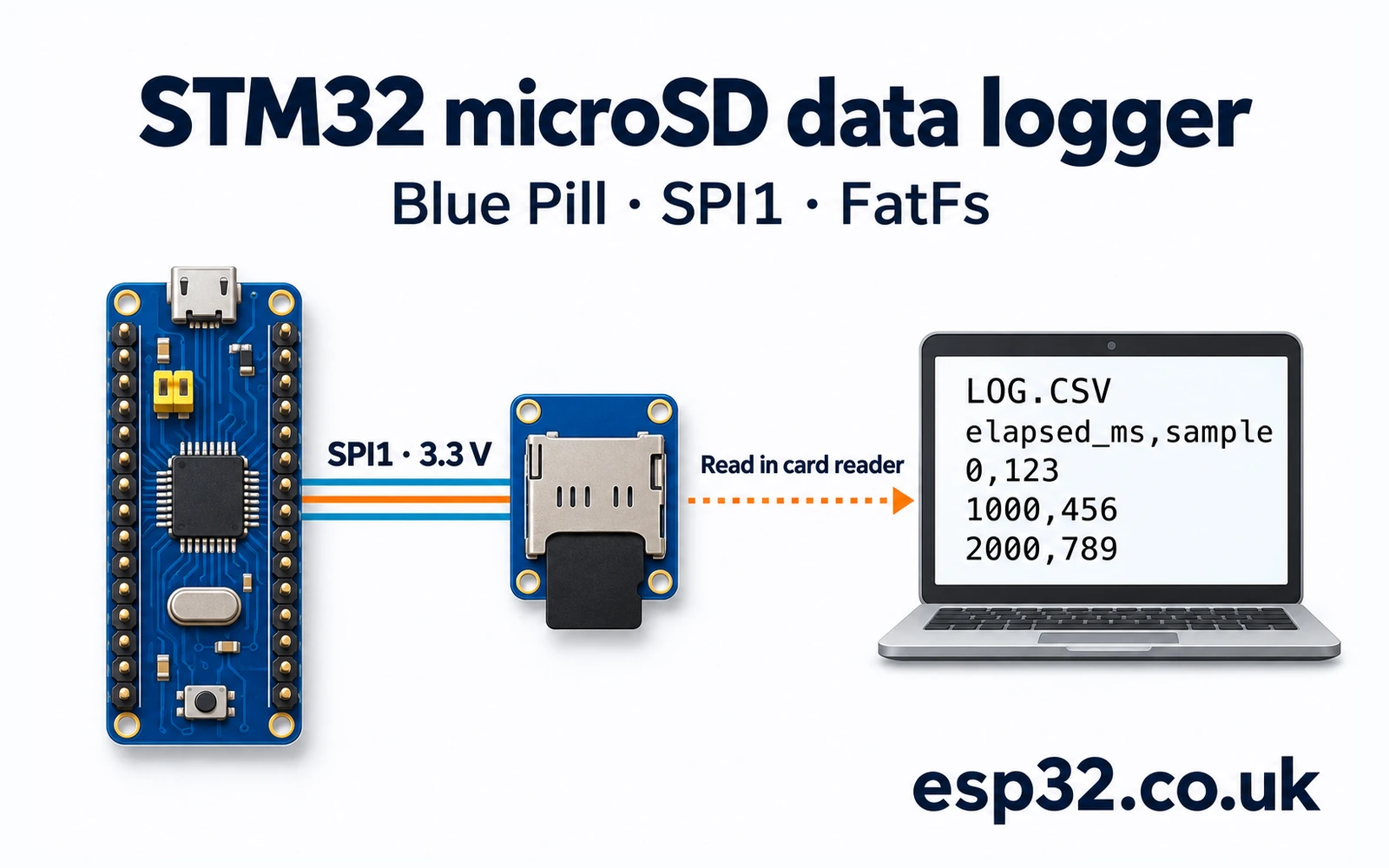
Connect a 3.3 V microSD socket to SPI1 on the STM32F103C8PriceAliExpress price Blue PillPriceAliExpress price and you can create a CSV log that a computer can read. The STM32PriceAliExpress price clocks bytes over SPI, the SD card exposes 512-byte sectors, and FatFs turns those sectors into files. The three layers have different failure modes. A card that responds to a command can still hold a filesystem that the firmware cannot mount.
In this esp32.co.uk/ guide, you'll wire an SDHC card, initialise it at 281.25 kHz and switch to 4.5 MHz for transfers. The STM32Cube HAL lab appends three known rows to LOG.CSV, syncs the file, closes it, then opens it for reading and compares the appended bytes. The known input makes the storage path easy to verify before adding a sensor.
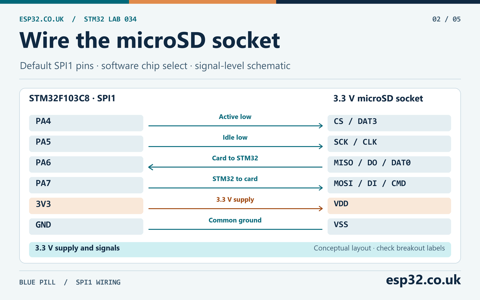
Quick answer. Use PA5 for SCK, PA6 for MISO, PA7 for MOSI and PA4 as a software chip select. Start with a FAT32-formatted microSDHC card, 3.3 V signalling and a common ground. In CubeMX select SPI1 full-duplex master, mode 0, 8-bit and software NSS. Add the matched FatFs files and the lab’s SPI disk driver so FatFs can read and write the card.
Choose the card and wire the socket
Use an STM32F103C8 Blue Pill with working SWD, a microSDHC card with a backed-up FAT32 volume, and a breakout designed for direct 3.3 V power and logic. A small card dedicated to the experiment is easier to recover if the card is removed during a write. You also need short jumper wires and a reader to inspect the finished file on a computer. A logic analyser is optional and can separate wiring, clock and protocol faults.
The C8 has two hardware SPI peripherals and 20 KiB of SRAM. The default SPI1 mapping uses PA5, PA6 and PA7. PA4 can serve as hardware NSS on this part, but the lab configures it as a regular output so the driver controls exactly when the card is selected. The same GPIO stays low through a complete read or write transaction. Check the markings against the Blue Pill pinout guide.
| Blue Pill | microSD in SPI mode | Signal direction or role |
|---|---|---|
| PA4 | CS, DAT3 | STM32 to card, active low |
| PA5 | SCK, CLK | STM32 to card, idle low |
| PA6 | MISO, DO, DAT0 | Card to STM32 |
| PA7 | MOSI, DI, CMD | STM32 to card |
| 3V3 from a suitable supply | VDD | 3.3 V at the socket |
| GND | VSS | Common signal and supply reference |
Some breakout boards print DI and DO from the card’s point of view. Connect PA7 to DI and PA6 to DO. A breakout that includes a regulator or level shifting may have different VCC requirements from a bare socket. Check the breakout circuit before applying power. For this wiring, use a socket board whose supply and signal pins are designed for direct 3.3 V operation. Use a card socket or breakout with the pull-ups appropriate to its design. For a bare SPI breakout with no CS pull-up, a 10 kΩ resistor from CS to 3.3 V can keep the card deselected while the MCU pin is still high impedance at reset.
Power quality is especially important during a write. A card can read successfully and fail when it draws a higher transient current. Measure 3.3 V at the socket under load to include any drop along the wiring. Use local bypass and bulk capacitance close to the socket. For a short bench connection, 100 nF in parallel with 10 µF is a starting arrangement to evaluate against the actual regulator and card. Keep the ground return short. If you use an external 3.3 V rail for the socket, keep the grounds common and arrange power so driven data pins cannot feed a powered-down device.
Check whether another device already uses PA4–PA7. The earlier SPI tutorial covers bus configuration and mixed peripheral requirements. This lab gives the SD card a dedicated SPI1 bus so the mode, speed, idle state and chip select are predictable. STM32 SPI, HAL and DMA guide
Start with a known filesystem
Choose a microSDHC card with an existing FAT32 volume. Copy its existing files to your computer before running the lab. If the card already contains a file called LOG.CSV, move that file aside to give the test a fresh starting point. The firmware opens that name in append mode and will add rows to it if it exists. The lab has no formatting command. It can mount a supported FAT volume presented by the disk layer and report a filesystem error when it cannot find one.
The card capacity class and filesystem are different settings. The disk layer uses block addresses as confirmed by the card’s OCR response. FatFs separately looks for a supported volume on those blocks. An SDXC card may pass the block-addressing check and still contain exFAT, which this configuration omits. A byte-addressed SDSC card is outside the lab’s transport scope. Use SDHC and FAT32 as the starting combination so both layers meet the intended setup.
Configure SPI1 in STM32CubeMX
Select the STM32F103C8 target and keep SYS debug on Serial Wire. The code expects a running HAL millisecond timebase and a 72 MHz APB2 clock. On a board with an 8 MHz HSE crystal, set HSE to Crystal/Ceramic Resonator, choose HSE as PLL input with the ×9 multiplier, and use PLL as SYSCLK. Set AHB to divide by 1, APB1 to divide by 2 and APB2 to divide by 1. Confirm the actual board oscillator and the resulting frequencies in the clock tree. If your clock is different, adapt and verify both SPI clock rates and the guard in the driver together.
| CubeMX setting | Lab value | Reason |
|---|---|---|
| SPI1 mode | Full-duplex master | Generate clocks while receiving card bytes |
| Frame and order | 8 bits, MSB first | Send command and payload bytes in SPI order |
| Clock polarity and phase | Low, first edge | SPI mode 0 |
| NSS | Software | PA4 controls the card select independently |
| Initial baud prescaler | 256 | 72 MHz ÷ 256 = 281.25 kHz |
| Working baud prescaler | 16, set by the driver | 72 MHz ÷ 16 = 4.5 MHz after initialisation |
| TI mode and hardware CRC | Disabled | The driver handles the SD wire framing |
| PA4 | GPIO push-pull output, initial High | Card stays deselected during setup |
Generate the project with SPI1 and the normal HAL SPI, GPIO and RCC support. Configure PA6 as the SPI1 input. Use the default, non-remapped PA5–PA7 pins. Ensure the generated GPIO setup drives the PA4 output latch high before configuring it as an output. Leave SPI interrupts and DMA out of the lab. It uses blocking calls in the foreground and depends on the timebase continuing to advance for its timeout checks. Follow the CubeMX and STM32CubeIDE setup guide for project generation and SWD debugging.
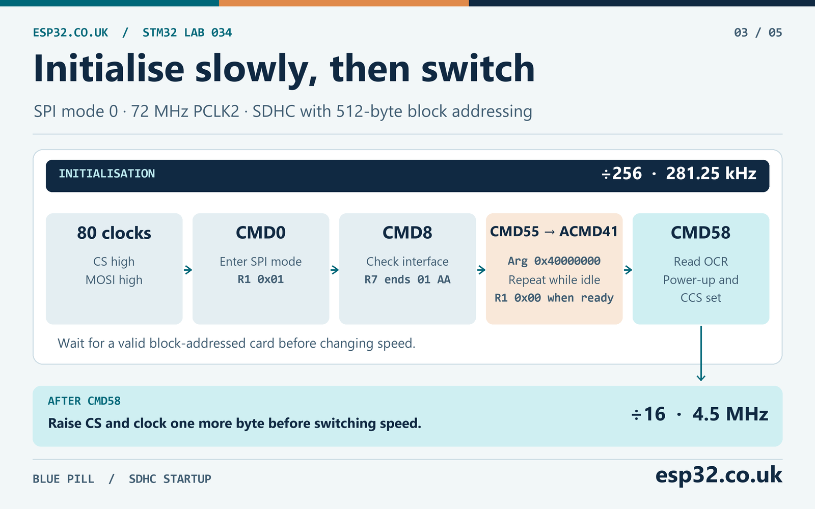
The code applies the slow setting even if the peripheral has previously been used at the faster rate. On this setup the APB2 bus clock feeds SPI1. The clock multiplication rule for some timers does not apply to SPI. At 281.25 kHz, 80 clocks take about 284 µs. The example also waits 10 ms after setting up the low-speed peripheral, before sending those clocks with CS and MOSI high. This delay assumes the board supply has already risen and is stable.
Use 4.5 MHz as the starting data rate. At that rate, shifting a 512-byte payload alone takes about 0.91 ms. Commands, data tokens, read polling, software gaps, card programming and filesystem work all increase the elapsed time. The DS5319 SPI limit for this MCU and the card’s supported operating mode both matter if you later change the prescaler. Measure the signal at the socket after any clock change.
Understand the card initialisation
At power-up the driver keeps CS high and sends ten bytes of 0xFF, providing 80 clock cycles with the card deselected and its command input high. It then selects the card and sends CMD0 with a valid CRC for that command. A working SPI-mode card replies with R1 0x01, indicating idle. The first R1 byte has bit 7 clear. Repeated 0xFF indicates that no such response arrived in the polling window.
| Stage | Command or bus action | Expected result for the lab card |
|---|---|---|
| Preclock | CS high, ten 0xFF bytes | 80 clocks while deselected |
| Enter SPI idle | CMD0, argument 0 | R1 0x01 |
| Check the interface | CMD8, argument 0x000001AA | R1 0x01 and R7 voltage/check pattern ending 01 AA |
| Finish power-up | Repeat CMD55 then ACMD41, argument 0x40000000 for ACMD41 | ACMD41 R1 changes from 0x01 to 0x00 |
| Check addressing | CMD58 | R1 0x00, OCR power-up and CCS bits set |
| Transfer | Raise CS, finish the transaction, then change the prescaler | SPI1 uses 4.5 MHz for sectors |
CMD8 checks that the card recognises the requested voltage range and returns the check pattern. Each ACMD41 attempt is preceded by CMD55. Its HCS bit tells the card that the host supports high-capacity addressing. HCS is a host request. The driver still checks the card’s CCS bit in the OCR from CMD58. The argument of CMD17 or CMD24 is then the logical sector number itself. For instance, LBA 2,048 is argument 0x00000800. Multiplying by 512 would select a different sector on a block-addressed card.
The lab uses the fixed CMD0 and CMD8 CRC bytes 0x95 and 0x87 for their fixed arguments. It uses the default SPI CRC-off policy after entry. For block reads it clocks out the two CRC bytes to finish the transaction. For writes it supplies two dummy CRC bytes. A production transport may enable the card’s CRC checks and implement the corresponding software CRC handling. STM32 SPI hardware CRC and the SD protocol’s command and data CRC fields are separate mechanisms.
Keep the timing visible when debugging the ACMD41 loop. A single idle reply is normal while the card powers up. A repeated idle reply through the entire initialisation budget is a fault condition for the lab. The loop uses an unsigned elapsed-time check, including across HAL tick rollover, and delays briefly between attempts. The 2 s limit in the code is a lab policy for the polling loop. Individual HAL transactions also have their own bounded waits.
Connect FatFs to the SPI disk driver
FatFs calls a small platform interface for sector access. In this project disk_initialize() brings up drive 0, disk_status() returns its state, disk_read() and disk_write() transfer one or more sectors, and disk_ioctl(CTRL_SYNC) waits for the device to be ready. The filesystem passes an LBA and a buffer. The SPI layer has no concept of directories or filenames.
Use the tagged ST FatFs R0.16 patch 2 source. Add ff.c, ff.h and diskio.h. Use the lab’s ffconf.h or rename the tag’s ffconf_template.h to ffconf.h and apply the configuration settings below. Add the lab listings as sd_spi_diskio.c, sd_csv.c and sd_csv.h. Place the source files in compiled project folders, add the header paths to the C compiler settings and build as C11.
This integration uses the direct disk_* functions. Leave CubeMX’s FatFs middleware unchecked for this project so there is one FatFs build, one ffconf.h and one implementation of the disk interface. The separately obtained ff.c provides the filesystem. The supplied disk driver provides its hardware hooks. If you add the source manually, keep the original licence notices in the upstream files.
| Configuration | Value | Effect |
|---|---|---|
| FF_VOLUMES | 1 | Drive 0 maps directly to the SD card |
| FF_MIN_SS and FF_MAX_SS | 512 | Fixed 512-byte sector size |
| FF_LBA64 and FF_FS_EXFAT | 0 | 32-bit LBA and FAT-only volume support |
| FF_USE_LFN | 0 | Use short filenames such as LOG.CSV |
| FF_FS_TINY | 1 | Share the volume’s sector window across files |
| FF_FS_NORTC | 1 | Use the configured fixed date for filesystem metadata |
| FF_USE_MKFS and FF_USE_TRIM | 0 | No formatting or discard commands |
| FF_FS_REENTRANT | 0 | Use one foreground owner for this volume and driver |
The supplied ffconf.h matches R0.16. If the compiler reports a revision mismatch, check which header it picked and confirm that the three upstream files are from the same tag. The fixed timestamp is a filesystem metadata setting. It leaves the sample time in the CSV under application control. To record date and time per sample, add an RTC timestamp to the row and define how the device handles a clock that hasn’t been set. STM32 RTC and VBAT retention guide
Transfer one sector at a time
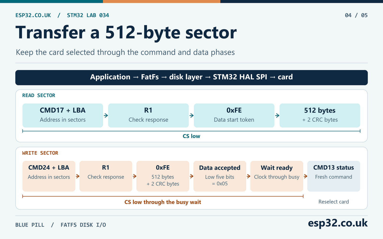
On a read, the driver sends CMD17, checks R1, and waits for a 0xFE data start token. It transmits dummy bytes so the card can clock out 512 data bytes and the CRC field. A token other than the expected start token causes the read to fail. On a write, CMD24 sets the LBA. The host then sends the start token, 512 bytes and the two CRC-field bytes. The response token’s low five bits must equal 0x05 for accepted data. The card can still be busy after acceptance. The driver clocks the card until it is ready and checks CMD13 status before treating that sector write as complete.
The example leaves CS asserted during each command and its data phase, then raises CS and sends another dummy byte. When FatFs requests several sectors, the driver walks the full request using successive single-block commands. That design is easy to inspect on a logic analyser. Multiblock transfers with CMD18 and CMD25 are a separate optimisation with different stop handling. A transport error marks the drive uninitialised so later calls fail clearly or reinitialise through a fresh mount.
#include "stm32f1xx_hal.h"
#include "diskio.h"
#include <stdbool.h>
#include <string.h>

#if FF_MIN_SS != 512 || FF_MAX_SS != 512 || FF_LBA64 || FF_FS_READONLY || FF_USE_MKFS
#error "Use the fixed-sector, writable FatFs lab configuration."
#endif

extern SPI_HandleTypeDef hspi1;
volatile BYTE sd_last_cmd = 0xFF;
volatile BYTE sd_last_r1 = 0xFF;
volatile BYTE sd_last_write_token = 0xFF;
static DSTATUS disk_state = STA_NOINIT;
static BYTE dummy[512];

enum { CARD_WAIT_MS = 750, BLOCK_WAIT_MS = 300, INIT_WAIT_MS = 2000 };

static bool exchange(BYTE tx, BYTE *rx)
{
    return HAL_SPI_TransmitReceive(&hspi1, &tx, rx, 1, 10) == HAL_OK;
}

static bool wait_ready(uint32_t timeout)
{
    uint32_t start = HAL_GetTick();
    BYTE value;
    do {
        if (!exchange(0xFF, &value)) {
            return false;
        }
        if (value == 0xFF) {
            return true;
        }
    } while (HAL_GetTick() - start < timeout);
    return false;
}

static bool select_card(void)
{
    HAL_GPIO_WritePin(GPIOA, GPIO_PIN_4, GPIO_PIN_RESET);
    return wait_ready(CARD_WAIT_MS);
}

static bool release_card(void)
{
    BYTE ignored;
    HAL_GPIO_WritePin(GPIOA, GPIO_PIN_4, GPIO_PIN_SET);
    return exchange(0xFF, &ignored);
}

/* Called with CS low. Allow up to ten byte exchanges to find R1. */
static bool command(BYTE cmd, uint32_t argument, BYTE *r1)
{
    BYTE frame[6] = {
        (BYTE)(0x40U | cmd), (BYTE)(argument >> 24), (BYTE)(argument >> 16),
        (BYTE)(argument >> 8), (BYTE)argument, 0x01
    };
    if (cmd == 0) {
        frame[5] = 0x95;
    } else if (cmd == 8) {
        frame[5] = 0x87;  /* For the fixed CMD8 argument 0x000001AA. */
    }
    sd_last_cmd = cmd;
    sd_last_r1 = 0xFF;
    if (HAL_SPI_Transmit(&hspi1, frame, sizeof frame, 10) != HAL_OK) {
        return false;
    }
    for (unsigned n = 0; n < 10; ++n) {
        if (!exchange(0xFF, r1)) {
            return false;
        }
        if ((*r1 & 0x80U) == 0) {
            sd_last_r1 = *r1;
            return true;
        }
    }
    return false;
}

static bool query(BYTE cmd, uint32_t arg, BYTE *r1, BYTE *tail, unsigned length)
{
    bool ok = select_card() && command(cmd, arg, r1);
    /* Read an extended response only after an R1 with no error bits. */
    if (ok && *r1 <= 1) {
        for (unsigned i = 0; i < length && ok; ++i) {
            ok = exchange(0xFF, &tail[i]);
        }
    }
    return release_card() && ok;
}

static bool set_speed(uint32_t prescaler)
{
    hspi1.Init.BaudRatePrescaler = prescaler;
    return HAL_SPI_Init(&hspi1) == HAL_OK;
}

static bool initialise_sdhc(void)
{
    BYTE r1, r7[4], ocr[4];
    HAL_GPIO_WritePin(GPIOA, GPIO_PIN_4, GPIO_PIN_SET);
    if (hspi1.Instance != SPI1 || HAL_RCC_GetPCLK2Freq() != 72000000U ||
        !set_speed(SPI_BAUDRATEPRESCALER_256)) {
        return false;
    }
    memset(dummy, 0xFF, sizeof dummy);
    HAL_Delay(10);
    if (HAL_SPI_Transmit(&hspi1, dummy, 10, 10) != HAL_OK ||
        !query(0, 0, &r1, NULL, 0) || r1 != 1 ||
        !query(8, 0x1AA, &r1, r7, sizeof r7) || r1 != 1 ||
        (r7[2] & 0x0FU) != 1 || r7[3] != 0xAA) {
        return false;
    }

    uint32_t start = HAL_GetTick();
    do {
        if (!query(55, 0, &r1, NULL, 0) || r1 > 1 ||
            !query(41, UINT32_C(0x40000000), &r1, NULL, 0) || r1 > 1) {
            return false;
        }
        if (r1 == 0) {
            break;
        }
        HAL_Delay(2);
    } while (HAL_GetTick() - start < INIT_WAIT_MS);

    /* OCR bits 31 and 30 are power-up complete and block addressing. */
    return r1 == 0 && query(58, 0, &r1, ocr, sizeof ocr) && r1 == 0 &&
           (ocr[0] & 0xC0U) == 0xC0U && set_speed(SPI_BAUDRATEPRESCALER_16);
}

static bool read_block(LBA_t sector, BYTE *dst)
{
    BYTE r1, token = 0xFF, crc[2];
    bool ok = select_card() && command(17, sector, &r1) && r1 == 0;
    uint32_t start = HAL_GetTick();
    while (ok && token == 0xFF && HAL_GetTick() - start < BLOCK_WAIT_MS) {
        ok = exchange(0xFF, &token);
    }
    ok = ok && token == 0xFE &&
         HAL_SPI_TransmitReceive(&hspi1, dummy, dst, 512, 100) == HAL_OK &&
         HAL_SPI_TransmitReceive(&hspi1, dummy, crc, 2, 10) == HAL_OK;
    return release_card() && ok;
}

static bool write_block(LBA_t sector, const BYTE *src)
{
    BYTE r1, response = 0xFF, ignored, status;
    const BYTE prefix[] = {0xFF, 0xFE};
    sd_last_write_token = 0xFF;
    bool ok = select_card() && command(24, sector, &r1) && r1 == 0 &&
              HAL_SPI_Transmit(&hspi1, prefix, sizeof prefix, 10) == HAL_OK &&
              HAL_SPI_Transmit(&hspi1, src, 512, 100) == HAL_OK &&
              HAL_SPI_Transmit(&hspi1, dummy, 2, 10) == HAL_OK;
    for (unsigned n = 0; ok && response == 0xFF && n < 8; ++n) {
        ok = exchange(0xFF, &response);
    }
    sd_last_write_token = response;
    /* Supply clocks after the response, then wait for programming to finish. */
    ok = ok && exchange(0xFF, &ignored) && wait_ready(CARD_WAIT_MS) &&
         (response & 0x1FU) == 0x05U;
    return release_card() && ok && query(13, 0, &r1, &status, 1) &&
           r1 == 0 && status == 0;
}

DSTATUS disk_initialize(BYTE drive)
{
    if (drive != 0) {
        return STA_NOINIT;
    }
    if (disk_state != 0 && initialise_sdhc()) {
        disk_state = 0;
    }
    return disk_state;
}

DSTATUS disk_status(BYTE drive)
{
    return drive == 0 ? disk_state : STA_NOINIT;
}

DRESULT disk_read(BYTE drive, BYTE *dst, LBA_t sector, UINT count)
{
    if (drive != 0 || dst == NULL || count == 0 || sector > UINT32_MAX - (count - 1U)) {
        return RES_PARERR;
    }
    if (disk_state != 0) {
        return RES_NOTRDY;
    }
    for (UINT n = 0; n < count; ++n, ++sector, dst += 512) {
        if (!read_block(sector, dst)) {
            disk_state = STA_NOINIT;
            return RES_ERROR;
        }
    }
    return RES_OK;
}

DRESULT disk_write(BYTE drive, const BYTE *src, LBA_t sector, UINT count)
{
    if (drive != 0 || src == NULL || count == 0 || sector > UINT32_MAX - (count - 1U)) {
        return RES_PARERR;
    }
    if (disk_state != 0) {
        return RES_NOTRDY;
    }
    for (UINT n = 0; n < count; ++n, ++sector, src += 512) {
        if (!write_block(sector, src)) {
            disk_state = STA_NOINIT;
            return RES_ERROR;
        }
    }
    return RES_OK;
}

DRESULT disk_ioctl(BYTE drive, BYTE request, void *buffer)
{
    (void)buffer;
    if (drive != 0 || request != CTRL_SYNC) {
        return RES_PARERR;
    }
    if (disk_state != 0) {
        return RES_NOTRDY;
    }
    bool ready = select_card();
    if (release_card() && ready) {
        return RES_OK;
    }
    disk_state = STA_NOINIT;
    return RES_ERROR;
}
The driver’s three volatile diagnostic bytes are visible in the debugger. sd_last_cmd and sd_last_r1 describe the most recent attempted command. sd_last_write_token holds the most recent write response byte. A later status command can replace the command and R1 fields, so inspect all three. Treat them as snapshots. For a sequence across several commands, capture the bus traffic instead.
Create, sync and verify the CSV file
Use the public function in sd_csv.h after the generated GPIO and SPI initialisation. It mounts the volume immediately with f_mount(&filesystem, "0:", 1). Immediate mounting makes initialisation and volume errors visible at that line. A deferred mount would register the filesystem object and postpone the checks until the first file operation.
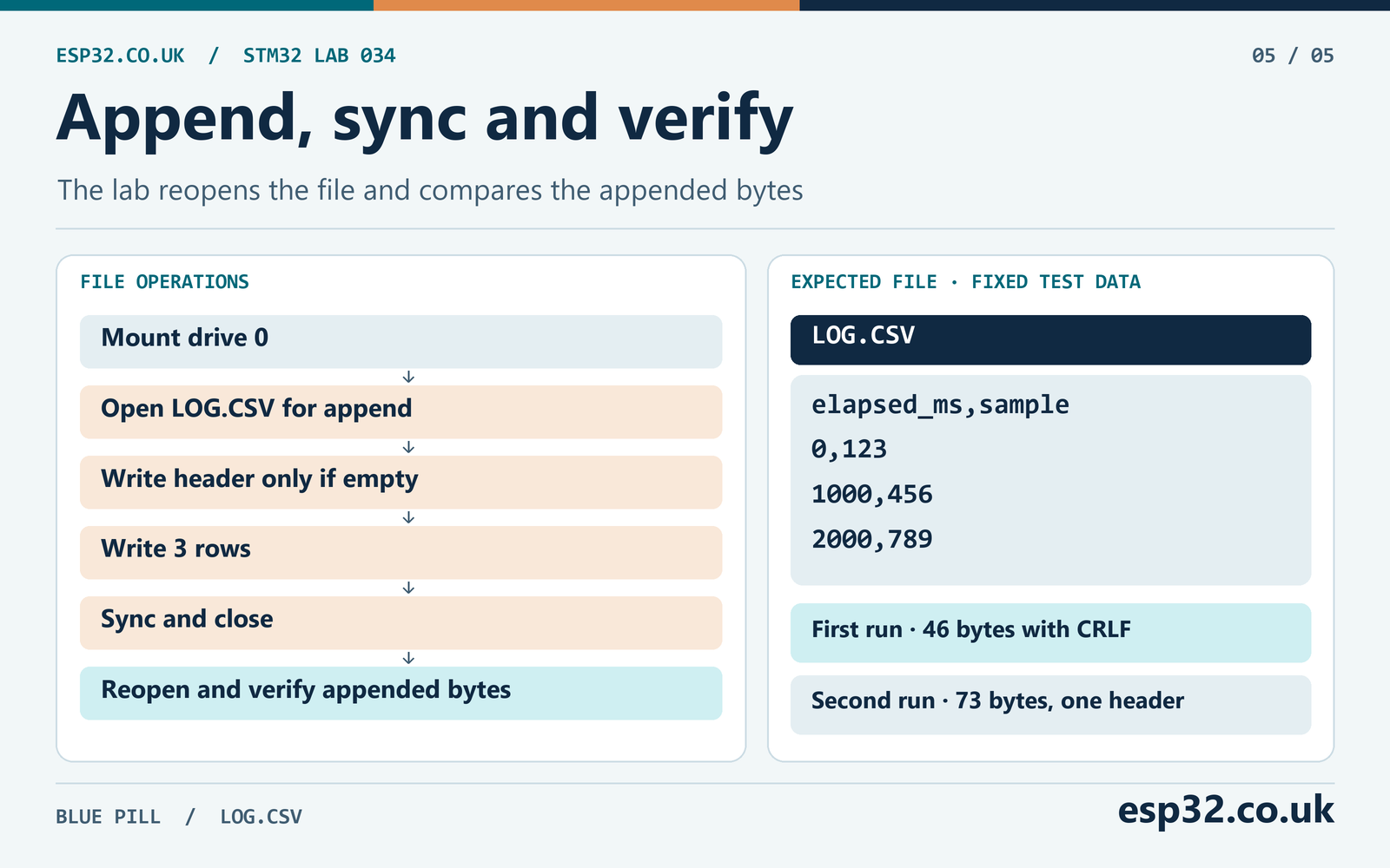
The logger opens 0:/LOG.CSV with FA_WRITE | FA_OPEN_APPEND. FatFs creates the file if needed and places the write position at the end of an existing file. The program adds the header only if the file is empty, then remembers the offset where the sample rows start. It uses the file byte count returned by f_write() as well as the result code. A short write can occur when the volume runs out of space even though the function returns FR_OK.
#ifndef SD_CSV_H
#define SD_CSV_H

#include "ff.h"

FRESULT SdLog_RunDemo(void);

#endif
#include "sd_csv.h"
#include <string.h>
static FATFS filesystem;
static const TCHAR path[] = "0:/LOG.CSV";
static const char header[] = "elapsed_ms,sample\r\n";
static const char rows[] = "0,123\r\n1000,456\r\n2000,789\r\n";
static FRESULT write_exact(FIL *file, const void *bytes, UINT length)
{
UINT written = 0;
FRESULT result = f_write(file, bytes, length, &written);
if (result == FR_OK && written != length) {
return FR_DENIED; /* Report a short write, for example on a full volume. */
}
return result;
}
static FRESULT close_with_result(FIL *file, FRESULT earlier)
{
FRESULT closed = f_close(file);
return earlier == FR_OK ? closed : earlier;
}
static FRESULT append_rows(FSIZE_t *first_row)
{
FIL file;
FRESULT result = f_open(&file, path, FA_WRITE | FA_OPEN_APPEND);
if (result != FR_OK) {
return result;
}
if (f_size(&file) == 0) {
result = write_exact(&file, header, sizeof header - 1U);
}
*first_row = f_tell(&file);
if (result == FR_OK) {
result = write_exact(&file, rows, sizeof rows - 1U);
}
if (result == FR_OK) {
result = f_sync(&file);
}
return close_with_result(&file, result);
}
static FRESULT verify_rows(FSIZE_t first_row)
{
FIL file;
char actual[sizeof rows - 1U];
UINT read = 0;
FRESULT result = f_open(&file, path, FA_READ);
if (result != FR_OK) {
return result;
}
result = f_lseek(&file, first_row);
if (result == FR_OK) {
result = f_read(&file, actual, sizeof actual, &read);
}
if (result == FR_OK && (read != sizeof actual || memcmp(actual, rows, sizeof actual) != 0)) {
result = FR_INT_ERR; /* Lab readback did not match the appended bytes. */
}
return close_with_result(&file, result);
}
FRESULT SdLog_RunDemo(void)
{
FSIZE_t first_row = 0;
FRESULT result = f_mount(&filesystem, "0:", 1);
if (result == FR_OK) {
result = append_rows(&first_row);
}
if (result == FR_OK) {
result = verify_rows(first_row);
}
FRESULT unmounted = f_mount(NULL, "0:", 0);
return result == FR_OK ? unmounted : result;
}Put the include in the generated main.c user include section. Put the volatile result in a global user section so you can inspect it after the call. Place the assignment inside the USER CODE BEGIN 2 section, after MX_GPIO_Init() and MX_SPI1_Init(). Let the generated main loop run afterwards. Calling the demo repeatedly from the loop would append a new batch every time it ran.
/* Includes */
#include "sd_csv.h"

/* PV */
volatile FRESULT log_result = FR_NOT_READY;

/* USER CODE 2 */
log_result = SdLog_RunDemo();
The append function calls f_sync(), then closes the file and preserves the earliest error if either step fails. The explicit sync illustrates what a long-running logger can do while keeping a file open. For a short application, a successful close also flushes the file. The demo reopens with FA_READ, seeks to the recorded offset and compares the exact bytes. It closes that handle and unregisters the volume before returning. A successful return means the application saw its appended data through the same filesystem and transport.
Check the file independently on a computer
Flash the firmware over SWD. Let the demo run to completion and inspect log_result. On a healthy bench run, it should be FR_OK. Stop the application after it returns, power the target down and remove the card. Mount the card on the computer and open LOG.CSV in a plain text editor. Expect one header and three data lines after a first successful run on a card with no previous log.
elapsed_ms,sample
0,123
1000,456
2000,789
These values are known test data. The millisecond column shows sample labels rather than measured delays. The file contains CRLF line endings, and the first batch takes 46 bytes including the header. Safely eject the card on the computer, reinsert it with the target powered down and start the same firmware again. The file should now contain the header once and the three rows twice, for 73 bytes. This checks that a reset does not overwrite the first batch. The demo assumes any existing LOG.CSV uses the same CSV schema and ends at a row boundary. Inspect an interrupted or unrelated file before letting the application append to it.
| Bench check | Expected observation |
|---|---|
| Power up without a card | Mount reports FR_NOT_READY if no valid card response arrives |
| Use a known FAT32 card | Drive initialises and the demo returns FR_OK |
| Inspect a fresh log on a computer | One header and three rows |
| Run again using the same card | Six data rows and one header |
| Use a card whose filesystem is exFAT | Mount may return FR_NO_FILESYSTEM after transport initialisation |
| Use a full FAT32 volume | Check the returned file result and byte count. A partial row can remain |
The firmware and ST’s SPI driver were compiled and linked for Cortex-M3 using a build fixture. The same disk and CSV source also ran against a simulated card backed by a FAT32 disk image. The simulation verified normal appends, write rejection and a missing-card response. The bench checks above verify the conditions that the simulator cannot represent, including wiring, SPI signal quality and actual card behaviour.
Plan the sample rate and flush interval
Once you can recover the expected file, replace the known samples with real measurements. Start by defining the row format and the sample time base. A logger that resets its elapsed counter on every boot should record a boot identifier or create a new session file. Otherwise two rows labelled 1000 can represent different runs. The application can also record a monotonic sample index and add wall-clock time when its RTC is valid. Our STM32 ADC and DMA guide covers acquisition on a separate part of the system.
Make the sample producer and file writer separate in the application’s design. A timer or DMA callback can collect a value and timestamp into a bounded RAM queue. A foreground consumer formats complete rows and writes them in batches. Keep FatFs calls out of the interrupt. The disk driver polls the SPI hardware and card, and the HAL timebase must run during those waits. If a card write stalls the foreground for longer than the queue can cover, count dropped samples or stop acquisition deliberately. A visible sequence gap is easier to diagnose than a logger that silently drops rows.
Estimate storage and buffering
Assume an average row length of 24 bytes including its line ending. At ten rows per second, the logger produces 240 bytes per second. Over one hour this is 864,000 bytes, about 844 KiB. Over one day it is 20,736,000 bytes, about 19.8 MiB. These are file payload figures. Cluster allocation and filesystem metadata use additional space. A CSV field with a growing timestamp or more digits changes the average row length.
| Budget example | Calculation | Result |
|---|---|---|
| Wire time for a sector payload | 512 × 8 ÷ 4,500,000 | About 0.91 ms |
| Average log rate | 24 bytes × 10 samples/s | 240 bytes/s |
| One day of rows | 240 × 86,400 | 20,736,000 bytes |
| Rows during a 750 ms stall | Round up 10 × 0.750 | 8 rows |
| Buffered bytes for those rows | 8 × 24 | 192 bytes before headroom |
A 750 ms wait is one timeout in the card driver, not a bound on a whole f_sync(). A single file operation may update several sectors. To size a queue, measure the worst gaps in the complete write and sync path on the cards you will deploy. Include repeated stalls, existing queue occupancy and time spent formatting rows. At 100 samples per second, the same 750 ms interval already calls for 75 queued samples before headroom. Store the compact binary readings in the queue if RAM is tight and format them only when draining it.
Batching also changes how often the filesystem updates metadata. A long-running logger can write several rows at a time and call f_sync() at an interval chosen for its power-loss budget. As a planning example, five seconds at ten rows per second corresponds to 50 rows between scheduled syncs. Extra rows may be sitting in the RAM queue or arriving while a sync is in progress. State the interval in terms of successful sync completion when evaluating data loss. Successful sync reduces the exposure window. It does not make the FAT volume transactional or make power removal during the next write safe.
Treat a write error as an uncertain file boundary
If f_write() is short or f_sync() fails, keep the file result and the last card diagnostics. Part of the batch or a metadata update may already have reached the card. Resending the same batch can duplicate rows or append after a partial line. When recovery matters, include a sample sequence number in each row and define a restart rule for incomplete lines. One option is to start a new file after an uncertain close, then reconcile the files later using their sample IDs.
Make card removal an explicit operation in the user interface. Stop collecting new rows, drain the queue, check sync and close, unmount, and then indicate that the card can be removed. The example uses a fixed card with no insertion switch. If the target continues running and you swap the card, the driver has no automatic way to invalidate its state and clear filesystem assumptions. For the bench procedure, power down between swaps. A field design with removable media needs card detection and coordinated stop, unmount and reinitialisation.
Troubleshoot STM32 microSD and FatFs errors
Start with the earliest failed stage. A timeout on CMD0 is different from a mount error after CMD58 succeeds. An SPI trace can show the command frame and card response with CS low. A filesystem result can show whether transport returned data that fails FAT validation. Keep the return values and card diagnostics together in the debugger or on a separate UART. STM32 UART and HAL diagnostics guide
| Symptom | First check | Likely area |
|---|---|---|
| CMD0 returns only 0xFF | Probe CS, clock, MOSI, MISO and VDD at the socket | No card reply, wiring or power |
| CMD8 has the illegal-command bit set | Verify the card type and frame bytes | Older card or bad command reception |
| ACMD41 remains idle | Confirm CMD55 before each poll and verify supply | Initialisation or card power |
| CMD58 returns with CCS clear | Check card capacity class | Byte addressing outside this lab |
| FR_NO_FILESYSTEM after initialisation | Check the card on a computer | Unsupported or damaged filesystem |
| Read works but a write fails | Inspect the write token, busy period and socket voltage | Supply transient, card fault or programming error |
| FR_DENIED from the lab | Check free space, attributes and write byte count | Full volume, access denial or short write |
| Failure appears only at 4.5 MHz | Try a slower transfer prescaler and scope the socket signals | Wiring length, level shift or signal integrity |
| Mount works once then fails after a swap | Reboot with the replacement card installed | Driver state and media change handling |
For a CMD0 diagnosis, trigger on the first falling edge of CS after the 80 startup clocks. The six MOSI bytes should be 40 00 00 00 00 95. If they decode correctly at the MCU but not at the socket, inspect the connection and common ground. When CMD0 succeeds but CMD8 fails, compare the 48 00 00 01 AA 87 frame and check that CS stays low through all four extra response bytes. Keep the analyser configured for mode 0 and probe at the card to include breakout circuitry in the measurement.
For failures after the speed change, leave the initialisation prescaler alone and lower only the working speed. A change from divide-by-16 to divide-by-32 halves the data clock to 2.25 MHz. A stable result at the lower speed gives you a reproducible signal-integrity test case. Check the breakout for level shifters with slow edges and check that jumpers are short. Compare the waveform during a command and during a full sector transfer. The latter can expose behaviour that a short command exchange misses.
When you have an oscilloscope, probe SCK and MISO at the STM32 pins using a short ground connection. Check whether MISO has settled before the rising clock edge at the receiver. Probe the same signal at the socket to see what the card is actually driving. A logic analyser can decode the digital traffic and identify the failing command, while an oscilloscope can show ringing, slow transitions or a supply dip that explains the bit errors.
The same strategy applies to a write that fails only during a large log. Confirm that the file opens and that initial blocks are accepted. Observe the 3.3 V rail and the data-out busy period while the card is programming. Check whether a watchdog deadline overlaps the stall. Raise a debug GPIO around f_sync() to measure the entire operation, including gaps in the SPI clock. STM32 watchdog and reset flags guide
Questions about Blue Pill microSD logging
Can I use SDIO on an STM32F103C8?
The C8’s documented peripherals include SPI and omit SDIO. Use the card’s SPI mode on this board. An STM32 board with SDIO uses a different peripheral and can use a wider card bus if the pins and socket are wired for it. The STM32F407VET6 board guide covers an example of that wiring.
Does FatFs choose which SPI peripheral to use?
The disk layer chooses SPI1 and PA4 in this project. FatFs sees drive 0 and a sector interface. To move to SPI2, change the handle, chip select, peripheral clock calculation and generated pins together. Recalculate the initialisation and working divisors from the SPI2 clock. The same file-layer calls can stay in place.
Why does the computer show a fixed modification date?
The lab’s FF_FS_NORTC setting makes FatFs use the date in ffconf.h. Real filesystem timestamps require the time hook expected by the matching FatFs release and a clock set to a valid date. Add that support separately from the sample timestamp so each remains useful if the other is unavailable.
Can I keep the file open while logging?
Yes. Keep the volume object and file handle valid for the whole session and give one task ownership. Sync periodically, check each result and close before removal. In that design a failure in one operation can leave later calls unable to proceed. Have the logger stop and record the earliest failure instead of continuing to feed a damaged session.
Datasheets & External Resources
| Source | What to check |
|---|---|
| ST DS5319 STM32F103x8/xB datasheet | C8 peripherals, SPI1 pins, electrical limits and SRAM |
| ST RM0008 reference manual | SPI clock selection, frame setup and master operation |
| ST ES096 medium-density errata | SPI CRC limitations relevant to adaptations |
| ST STM32F1 HAL SPI source v1.1.10 | Polling transfers, SPI initialisation and timeout behaviour |
| SD Association simplified specifications | Physical Layer v9.10, SPI initialisation and block transactions |
| FatFs application note | Disk port, memory usage and critical sections |
| FatFs f_sync documentation | Flush semantics and their use in data logging |