A Blue PillPriceAliExpress price data logger can record the right temperature and still produce unusable records if every reset puts the date back to the day the firmware was built. The STM32F103 has a real time clock that can keep counting when the processor loses power. To use it reliably, you need a clock source that runs from backup power, firmware that preserves the retained state, and a way to tell whether the time was ever set.
In this esp32PriceAliExpress price.co.uk/ guide, we will bring up the Blue PillAliExpress price’s 32.768 kHz crystal, store a UTC timestamp in the RTC counter, and report it over USART1. Then we will remove the main supply while keeping VBAT powered. The test has two distinct outcomes to check. The timestamp must survive, and the seconds must advance while the board is off. A retained timestamp that stands still is a clock fault, even if it looks convincing on the first line after boot.
The lab uses a genuine STM32F103C8T6Price with the STM32CubeF1 HAL for the project, timing and UART. It configures the RTC counter directly using the documented STM32F1 register sequence. This lets the calendar live entirely in the retained counter rather than depend on the contents of a C variable after a reset. You can start with a UART adapter and a multimeter. A separate, suitable supply for VBAT is needed for the power loss test.

What survives a reset on the STM32F103
The RTC on this chip is a 32-bit counter with a programmable prescaler and an alarm comparison register. It has no registers for the current month or year. The hardware increments the counter when the prescaler completes a period, and software decides what the value means. In this lab it represents seconds elapsed since midnight UTC on 1 January 2000. Calendar fields are calculated each time you display the timestamp.
That distinction matters when following a tutorial for a different STM32 family. Many newer parts store hour, minute and date fields in hardware. The F1 HAL offers familiar time and date functions, but the driver keeps its working date in RTC_HandleTypeDef.DateToUpdate. Its time functions can update that date and adjust the hardware counter as days pass. The code below owns the counter as a continuous epoch. Calling those HAL time or date functions on the same RTC would mix two different representations. See ST’s STM32F1 HAL RTC implementation.
The backup domain includes the RTC, backup data registers and the relevant clock control settings. The processor can reset while this domain keeps running. The independent watchdog reset from the STM32 watchdog tutorial is a useful example of why software should inspect retained state on boot. For the first test here, use the reset button. That isolates firmware restart from power supply behaviour.
| Event | What the application should expect |
|---|---|
| NRST while VDD is present | The processor restarts and the RTC can continue counting |
| VDD removed with valid VBAT and LSE | The RTC and backup data can persist while the CPU stops |
| VDD and VBAT both lost | Treat the old timestamp as invalid after power returns |
| Backup domain reset through RCC BDRST | RTC state and backup settings are cleared intentionally |
| Firmware starts by writing a default timestamp | The previous time is overwritten even with good backup power |
There is another distinction between persistence and accuracy. A marker in a backup register can tell you that this firmware previously finished setting the clock. It cannot tell you how far the crystal has drifted, when the last trusted synchronisation happened, or whether the time was entered correctly. We will use the marker for a simple validity check and measure the clock separately.
Inspect the board before connecting VBAT
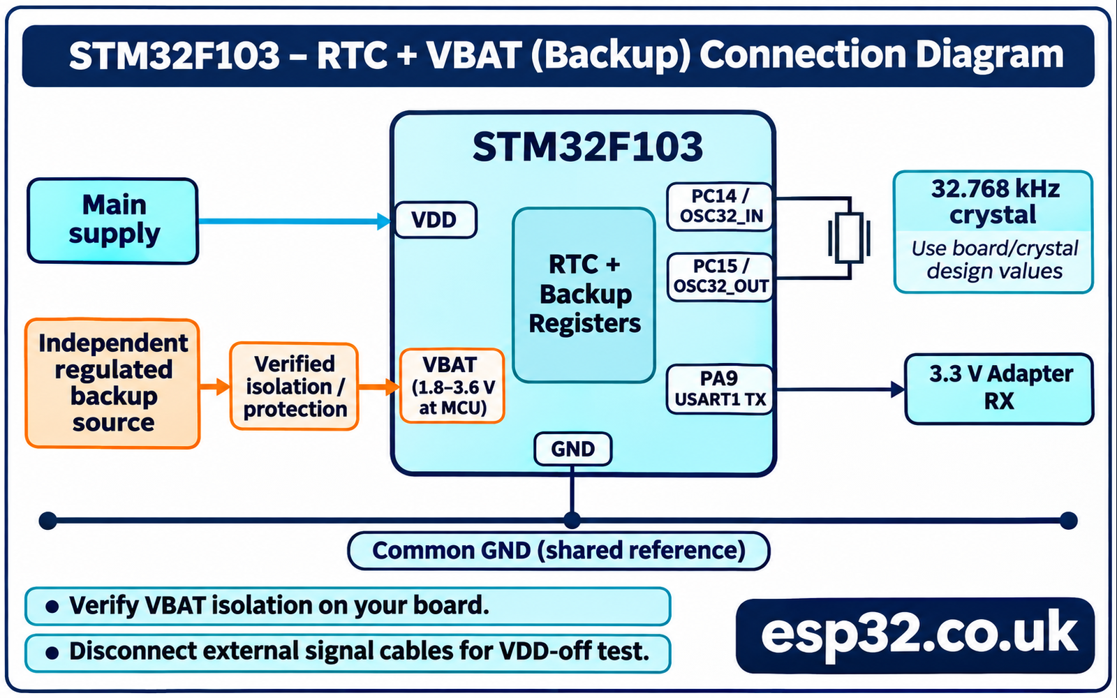
The board’s two crystals serve different jobs. A populated high speed crystal is usually used by the system clock. The small 32.768 kHz crystal for LSE connects across PC14 and PC15, which are OSC32_IN and OSC32_OUT on the STM32F103C8. Leave those pins for the oscillator. A missing crystal, incorrect load capacitors or an unsuitable board layout can keep LSERDY low even when the software is correct. Board revisions vary, so identify the crystal and its connection on the actual unit. ST STM32F103x8/xB datasheet
Find the VBAT pad or header position using the silkscreen, schematic and continuity measurements. Do continuity checks with the board disconnected from all power sources. Some variants route VBAT separately, while a particular board may tie it to the main 3.3 V rail. If it is tied to that rail, connecting a second source to the header can power the whole rail. Use a board or circuit that gives you an isolated, documented VBAT input for this test. The site’s Blue Pill pinout guide helps identify the names to look for.
The datasheet gives an operating range of 1.8–3.6 V at VBAT for these parts. Measure at the MCU’s supply pin or its verified header connection, after any isolation component. In a bench setup, use an appropriate regulated backup source with a common ground and protection suited to the board. STM32F1 can inject current toward VBAT during some VDD startup conditions. Follow ST’s battery backup circuit guidance and the source manufacturer’s requirements. A primary coin cell needs protection against charging current and a verified supply path. For designs without a separate backup source, follow ST’s VBAT connection guidance and expect the RTC to lose power with VDD. ST AN2586 hardware development guide
| Connection | What to verify before power-on |
|---|---|
| Main board supply | Use the input and voltage specified for your board |
| VBAT | Use a verified independent backup path within the MCU operating range |
| Backup ground | Common reference to board GND |
| PC14 and PC15 | LSE crystal circuit fitted and reserved for the oscillator |
| PA9 USART1_TX | Connect to RX on a 3.3 V logic UART adapter |
| UART GND | Common ground for observing the serial output |
| PA13 and PA14 | Keep SWD available for programming, then remove external connections for the off test |
Connect only the UART receive input and ground for this lab. There is no need to connect the adapter’s supply lead or its transmit output. During the backup test, remove the USB cable, debugger and other signal connections that might feed the board. A power LED going out is a useful clue, but measure VDD to confirm the rail has actually collapsed. Measure VBAT separately. It should still be within range. The serial terminal cannot report while the CPU is off, so record the last timestamp before the test and compare it with the first one after power returns.
Select the oscillator and calculate the prescaler
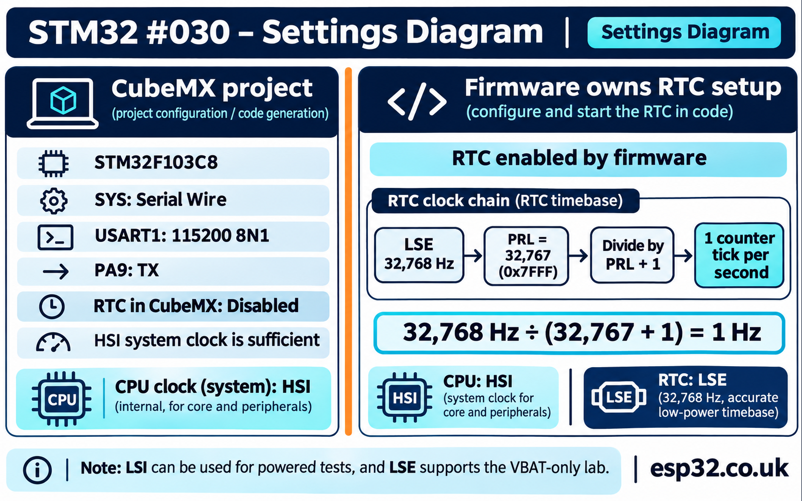
The three RTC clock choices on this part are LSE, LSI and HSE divided by 128. Only the LSE crystal path in this lab is used to keep counting from VBAT alone. The internal LSI oscillator is useful for exercising RTC code on a powered board that lacks a crystal. Its nominal frequency and accuracy differ from LSE, so changing only the source in a 32.768 kHz configuration will also change the second length. HSE divided by 128 depends on the high speed external oscillator and does not meet the backup goal. ST RM0008, RCC and RTC chapters
| Source | Typical reason to choose it | Consequence for this lab |
|---|---|---|
| LSE, nominally 32.768 kHz | A low frequency crystal provides a stable timebase | Supports the independent backup experiment |
| LSI, nominally 40 kHz on STM32F103 | A powered bench test without a crystal | Requires a suitable prescaler and will not keep counting on VBAT alone |
| HSE divided by 128 | An already available powered high speed reference | The RTC depends on the HSE source and its availability |
The counter rate is the input frequency divided by PRL + 1. With 32,768 input cycles per second, the reload value is 32,767, or 0x7FFF. The high portion of the 20-bit reload is therefore zero and the low portion is 0x7FFF. A value of 32,768 would divide by 32,769 and introduce about 30.5 ppm of slow error even with an ideal crystal. That is roughly 2.64 seconds per day. Crystal error and prescaler error are separate, so settle the divider arithmetic before measuring drift.
RTC source selection is stored in the backup domain. A board previously used with LSI may boot this LSE example with that old source still selected. The lab reports a source conflict so you can diagnose it. If you intend to migrate an existing clock, read and record the old timestamp first. A deliberate backup domain reset will erase the retained data and require a new time setting. Routine startup has no reason to pulse BDRST.
Generate the CubeMX project
Create an STM32CubeMX project for STM32F103C8Tx with the STM32CubeF1 HAL. Select Serial Wire under SYS and enable USART1 in asynchronous mode at 115200 baud, eight data bits, no parity and one stop bit. Use the default PA9 TX mapping. You can keep the system clock on HSI for this experiment. The CPU clock may change the UART divider and software timing, but it does not determine the one second RTC tick. Check that the UART project prints correctly on its own before adding the clock.
Leave RTC disabled in the CubeMX peripheral view for this version of the lab, and leave LSE setup to the example. The RTC remains available in the device header through CMSIS. The example enables PWR and BKP access, starts LSE, and selects and enables the RTC clock. This gives one piece of code ownership of those operations. Inspect generated SystemClock_Config() and the initialisation calls for backup-domain configuration if you are adapting an existing project. Remove competing RTC setup from that project before running this lab. The CubeMX setup guide and STM32 UART tutorial cover project generation and terminal setup.
The example uses the generated huart1 handle and adds three calls to main.c through the CubeMX user code sections. Keep the code in the package’s firmware directory handy. Add rtc_lab.h to Core/Inc and rtc_lab.c to Core/Src, or their equivalents in the generated project. Check that HAL_PWR_MODULE_ENABLED is defined in the project’s HAL configuration and that stm32f1xx_hal_pwr.c is built. The lab expects the normal HAL millisecond tick to be running. Its wait loops belong in the foreground, after HAL_Init(), so the timeout can advance.
Define what a timestamp means
The lab accepts dates from 2000 through 2099. A full day is treated as 86,400 seconds, and the Gregorian leap-year rule adds 29 February in leap years. Time is kept in UTC, so a daylight saving change cannot create duplicate wall-clock timestamps in the logger. Calendar formatting for a local timezone belongs at the display or export boundary. The epoch assumes ordinary 86,400-second days and does not represent a leap second as a distinct 23:59:60 value.
As a worked example, midnight on 1 January 2026 is 9,497 days after the epoch, or 820,540,800 seconds. There are 26 ordinary year lengths and seven extra leap days in that interval. Adding 12 hours produces 820,584,000. This value fits in the unsigned 32-bit hardware counter. The application’s 2099 end date is a deliberate policy with a clean boundary. A hardware counter ticking at 1 Hz can reach about 136 years before wrap, so the supported date range ends first.
Use an unsigned type for seconds and for reading the raw register halves. Packing a signed halfword into the top of an integer is an easy way to introduce sign extension or shift problems. Also reject invalid dates such as 29 February 2025. Normalising an invalid date to March can conceal a mistake in the operator’s input. When you convert back, remove whole years and months from the day count, then split the remainder of the seconds into hours, minutes and seconds. At most 100 years are traversed, which is small compared with the one second output interval.
Implement startup, time setting and serial output
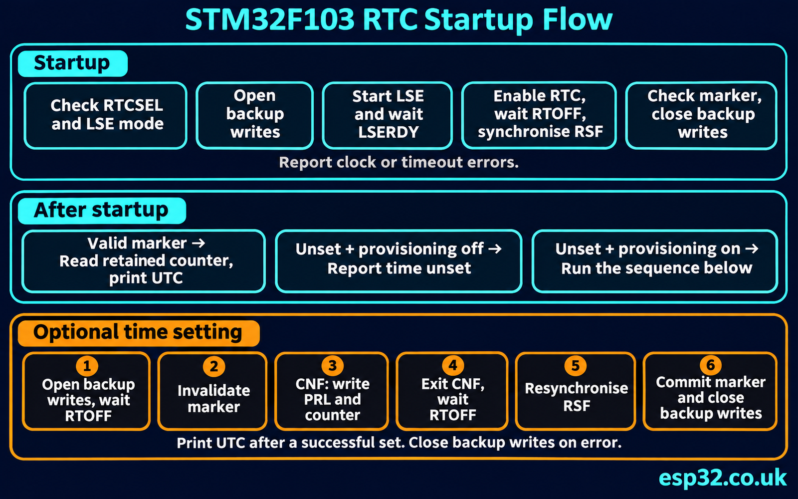
The startup code first confirms that RTCSEL is unset or already set to LSE crystal mode. It enables access to the backup domain, waits for the write gate, starts the oscillator if needed and waits for LSERDY. Then it enables the RTC and synchronises the APB view using RSF. Reading counter registers too early can give a stale value even when the oscillator is working. The synchronisation wait is separate from the longer crystal startup wait so the reported error identifies the stage that failed.
Updating the prescaler and counter uses the STM32F1 configuration handshake. Wait for RTOFF, set CNF, write the high and low pieces, clear CNF, then wait for RTOFF again. This resembles the private counter-writing sequence in the ST driver. The clock set routine invalidates the backup marker before changing the timestamp and writes the marker only after the peripheral update completes. If power fails during that sequence, a later boot will require the operator to set the clock again. The app closes backup write access when it finishes.
To read a coherent 32-bit value from the two 16-bit halves, sample high, low, high. If the two high values differ, retry. A rollover across a 0xFFFF low word can otherwise pair the old high half with the new low half and make the displayed time jump backwards. This check protects the read across a natural counter increment. It assumes a single foreground owner and no other code setting the RTC concurrently. An interrupt or second task that writes the counter would need application-level coordination.
The two files below build on the normal STM32F103 CMSIS and HAL headers in the generated project. The header exposes the entry points and leaves the board register details in the C file.
/* file: rtc_lab.h */
#ifndef RTC_LAB_H
#define RTC_LAB_H

#include <stdbool.h>
#include <stdint.h>

typedef struct {
    uint16_t year;
    uint8_t month, day, hour, minute, second;
} RtcLabDate;

typedef enum {
    RTC_LAB_OK = 0,
    RTC_LAB_SOURCE_CONFLICT,
    RTC_LAB_BACKUP_LOCKED,
    RTC_LAB_LSE_TIMEOUT,
    RTC_LAB_SYNC_TIMEOUT,
    RTC_LAB_UNSET,
    RTC_LAB_INVALID_DATE,
    RTC_LAB_WRITE_TIMEOUT,
    RTC_LAB_UNSTABLE
} RtcLabStatus;

bool RtcLab_ToSeconds(const RtcLabDate *date, uint32_t *seconds);
bool RtcLab_FromSeconds(uint32_t seconds, RtcLabDate *date);
RtcLabStatus RtcLab_Start(void);
RtcLabStatus RtcLab_Set(const RtcLabDate *date);
RtcLabStatus RtcLab_Read(RtcLabDate *date);

#endif
/* file: rtc_lab.c */
#include "rtc_lab.h"
#include "stm32f1xx_hal.h"
#define SECONDS_PER_DAY 86400u
#define RTC_RELOAD 32767u
#define RTC_MARKER 0x3A70u
#define RTC_STATUS_FLAGS (RTC_CRL_RSF | RTC_CRL_OWF | RTC_CRL_ALRF | RTC_CRL_SECF)
static bool leap(uint32_t year)
{
return year % 4u == 0u && (year % 100u != 0u || year % 400u == 0u);
}
static uint32_t month_days(uint32_t year, uint32_t month)
{
static const uint8_t lengths[] = {31,28,31,30,31,30,31,31,30,31,30,31};
return lengths[month - 1u] + (month == 2u && leap(year));
}
bool RtcLab_ToSeconds(const RtcLabDate *date, uint32_t *seconds)
{
if (!date || !seconds || date->year < 2000u || date->year > 2099u ||
date->month < 1u || date->month > 12u || date->day < 1u ||
date->day > month_days(date->year, date->month) || date->hour > 23u ||
date->minute > 59u || date->second > 59u) {
return false;
}
uint32_t days = date->day - 1u;
for (uint32_t year = 2000u; year < date->year; ++year) {
days += 365u + leap(year);
}
for (uint32_t month = 1u; month < date->month; ++month) {
days += month_days(date->year, month);
}
*seconds = days * SECONDS_PER_DAY + date->hour * 3600u +
date->minute * 60u + date->second;
return true;
}
bool RtcLab_FromSeconds(uint32_t seconds, RtcLabDate *date)
{
if (!date) return false;
uint32_t days = seconds / SECONDS_PER_DAY;
uint32_t year = 2000u;
while (year <= 2099u && days >= 365u + leap(year)) {
days -= 365u + leap(year);
++year;
}
if (year > 2099u) return false;
uint32_t month = 1u;
while (days >= month_days(year, month)) {
days -= month_days(year, month);
++month;
}
uint32_t tod = seconds % SECONDS_PER_DAY;
*date = (RtcLabDate){(uint16_t)year, (uint8_t)month, (uint8_t)(days + 1u),
(uint8_t)(tod / 3600u), (uint8_t)((tod / 60u) % 60u),
(uint8_t)(tod % 60u)};
return true;
}
static bool wait_set(volatile const uint32_t *reg, uint32_t mask, uint32_t ms)
{
uint32_t start = HAL_GetTick();
while ((*reg & mask) == 0u) {
if ((uint32_t)(HAL_GetTick() - start) >= ms) return false;
}
return true;
}
static bool lse_rtc_ready(void)
{
const uint32_t mask = RCC_BDCR_RTCSEL | RCC_BDCR_RTCEN |
RCC_BDCR_LSERDY | RCC_BDCR_LSEBYP;
const uint32_t expected = RCC_RTCCLKSOURCE_LSE | RCC_BDCR_RTCEN | RCC_BDCR_LSERDY;
return (RCC->BDCR & mask) == expected && (RTC->CRL & RTC_CRL_RSF) != 0u;
}
RtcLabStatus RtcLab_Start(void)
{
uint32_t source = RCC->BDCR & RCC_BDCR_RTCSEL;
if ((source != 0u && source != RCC_RTCCLKSOURCE_LSE) ||
(RCC->BDCR & RCC_BDCR_LSEBYP) != 0u) {
return RTC_LAB_SOURCE_CONFLICT;
}
__HAL_RCC_PWR_CLK_ENABLE();
__HAL_RCC_BKP_CLK_ENABLE();
HAL_PWR_EnableBkUpAccess();
RtcLabStatus result;
if (!wait_set(&PWR->CR, PWR_CR_DBP, 100u)) {
result = RTC_LAB_BACKUP_LOCKED;
} else {
SET_BIT(RCC->BDCR, RCC_BDCR_LSEON);
if (!wait_set(&RCC->BDCR, RCC_BDCR_LSERDY, 5000u)) {
result = RTC_LAB_LSE_TIMEOUT;
} else {
if (source == 0u) __HAL_RCC_RTC_CONFIG(RCC_RTCCLKSOURCE_LSE);
__HAL_RCC_RTC_ENABLE();
if (!wait_set(&RTC->CRL, RTC_CRL_RTOFF, 100u)) {
result = RTC_LAB_WRITE_TIMEOUT;
} else {
RTC->CRL = RTC_STATUS_FLAGS & ~RTC_CRL_RSF;
if (!wait_set(&RTC->CRL, RTC_CRL_RSF, 100u)) {
result = RTC_LAB_SYNC_TIMEOUT;
} else {
result = (BKP->DR1 == RTC_MARKER && (RTC->CRL & RTC_CRL_OWF) == 0u)
? RTC_LAB_OK : RTC_LAB_UNSET;
}
}
}
}
HAL_PWR_DisableBkUpAccess();
return result;
}
RtcLabStatus RtcLab_Set(const RtcLabDate *date)
{
uint32_t seconds;
if (!RtcLab_ToSeconds(date, &seconds)) return RTC_LAB_INVALID_DATE;
if (!lse_rtc_ready()) return RTC_LAB_SYNC_TIMEOUT;
HAL_PWR_EnableBkUpAccess();
if (!wait_set(&PWR->CR, PWR_CR_DBP, 100u)) {
HAL_PWR_DisableBkUpAccess();
return RTC_LAB_BACKUP_LOCKED;
}
RtcLabStatus result = RTC_LAB_WRITE_TIMEOUT;
if (wait_set(&RTC->CRL, RTC_CRL_RTOFF, 100u)) {
BKP->DR1 = 0u;
RTC->CRL = RTC_STATUS_FLAGS | RTC_CRL_CNF;
RTC->PRLH = 0u;
RTC->PRLL = RTC_RELOAD;
RTC->CNTH = seconds >> 16u;
RTC->CNTL = seconds & 0xFFFFu;
RTC->CRL = RTC_STATUS_FLAGS;
if (wait_set(&RTC->CRL, RTC_CRL_RTOFF, 100u)) {
RTC->CRL = RTC_STATUS_FLAGS & ~(RTC_CRL_OWF | RTC_CRL_RSF);
if (wait_set(&RTC->CRL, RTC_CRL_RSF, 100u)) {
BKP->DR1 = RTC_MARKER;
result = RTC_LAB_OK;
} else {
result = RTC_LAB_SYNC_TIMEOUT;
}
}
}
HAL_PWR_DisableBkUpAccess();
return result;
}
RtcLabStatus RtcLab_Read(RtcLabDate *date)
{
if (!date) return RTC_LAB_INVALID_DATE;
if (!lse_rtc_ready()) return RTC_LAB_SYNC_TIMEOUT;
if (BKP->DR1 != RTC_MARKER || (RTC->CRL & RTC_CRL_OWF) != 0u) {
return RTC_LAB_UNSET;
}
for (unsigned attempt = 0; attempt < 4u; ++attempt) {
uint32_t hi = RTC->CNTH & 0xFFFFu;
uint32_t lo = RTC->CNTL & 0xFFFFu;
if (hi == (RTC->CNTH & 0xFFFFu)) {
if ((RTC->CRL & RTC_CRL_OWF) != 0u) return RTC_LAB_UNSET;
return RtcLab_FromSeconds((hi << 16u) | lo, date)
? RTC_LAB_OK : RTC_LAB_INVALID_DATE;
}
}
return RTC_LAB_UNSTABLE;
}The status writes to CRL account for its write-zero-to-clear flags. Writing one to the other status flags preserves them as the program changes CNF, clears RSF for synchronisation or clears the overflow flag on a new time set. RTOFF is read-only. The setter also waits for fresh synchronisation before marking the updated timestamp as valid. Reserve backup register DR1 for this lab so another library cannot accidentally use the same marker. The same firmware also owns the RTC clock source and prescaler. The overflow flag can detect a wrap while it is observable, while the supported calendar range remains 2000–2099. A reset can clear RTC status flags, so an application designed to cover a full hardware wrap would need persistent rollover bookkeeping. If you later add tamper detection, reserve its pins and decide how an invalidated marker should be reported. ST RM0008, RTC register descriptions and backup registers
In main.c, add the following includes and user functions. Change the six values in the seed initializer to the UTC time you want to test. The initializer shown uses 2026-01-01 12:00:00 UTC to match the worked conversion. With RTC_LAB_PROVISION enabled, the time is written only when startup reports that the retained time is unset. Set it back to zero and rebuild once the first timestamp is printed. That makes loss of the backup supply visible as an unset status, rather than quietly restoring a stale seed.
/* USER CODE BEGIN Includes */
#include "rtc_lab.h"
#include <stdio.h>
#include <string.h>
/* USER CODE END Includes */

/* USER CODE BEGIN 0 */
#define RTC_LAB_PROVISION 0

static void rtc_log(const char *line)
{
    (void)HAL_UART_Transmit(&huart1, (const uint8_t *)line,
                           (uint16_t)strlen(line), 100u);
}

static const char *rtc_status_text(RtcLabStatus status)
{
    switch (status) {
    case RTC_LAB_OK:              return "OK";
    case RTC_LAB_SOURCE_CONFLICT: return "RTC source conflict";
    case RTC_LAB_BACKUP_LOCKED:   return "backup write access locked";
    case RTC_LAB_LSE_TIMEOUT:     return "LSE startup timeout";
    case RTC_LAB_SYNC_TIMEOUT:    return "RTC synchronisation timeout";
    case RTC_LAB_UNSET:           return "time unset or overflowed";
    case RTC_LAB_INVALID_DATE:    return "date outside supported range";
    case RTC_LAB_WRITE_TIMEOUT:   return "RTC write timeout";
    case RTC_LAB_UNSTABLE:        return "counter read unstable";
    default:                      return "unknown RTC status";
    }
}

static RtcLabStatus rtc_start_for_demo(void)
{
    RtcLabStatus status = RtcLab_Start();
#if RTC_LAB_PROVISION
    if (status == RTC_LAB_UNSET) {
        const RtcLabDate seed = {2026, 1, 1, 12, 0, 0};
        status = RtcLab_Set(&seed);
    }
#endif
    return status;
}

static void rtc_print(RtcLabStatus startup)
{
    RtcLabDate now = {0};
    RtcLabStatus status = startup == RTC_LAB_OK ? RtcLab_Read(&now) : startup;
    char line[64];
    if (status == RTC_LAB_OK) {
        (void)snprintf(line, sizeof line, "%04u-%02u-%02uT%02u:%02u:%02uZ\r\n",
                       (unsigned)now.year, (unsigned)now.month, (unsigned)now.day,
                       (unsigned)now.hour, (unsigned)now.minute, (unsigned)now.second);
    } else {
        (void)snprintf(line, sizeof line, "RTC: %s\r\n", rtc_status_text(status));
    }
    rtc_log(line);
}
/* USER CODE END 0 */

/* Add in USER CODE BEGIN 2, after USART1 init: */
/* RtcLabStatus rtc_startup = rtc_start_for_demo(); */

/* Add to the generated while (1) body in a user code region: */
/* rtc_print(rtc_startup);
   HAL_Delay(1000u); */
HAL_Delay(1000) controls the print interval. The RTC keeps its own pace, so the terminal may occasionally skip a timestamp when printing overhead and the two clock domains drift apart. Use consecutive counter reads or compare timestamps over a longer interval for rate measurements. With provisioning disabled, a newly erased backup domain should produce a readable “time unset” message. This behaviour is worth observing on the bench before adding any power switch.
Prove the clock survives a restart and a power cut
Start with VDD and the validated backup supply connected. Enable provisioning once, flash the example and open a serial terminal. The example should print a UTC timestamp ending in Z. Confirm that it advances over several seconds. If the value never changes, inspect RCC->BDCR for the ready and enable flags, then inspect the raw counter in two snapshots. This splits a stopped timebase from a formatter problem.
Disable provisioning, flash the reporting build and verify that the timestamp still advances. A debug configuration can perform its own reset or initialisation scripts, so observe the programme running independently of an attached debug session. Press NRST and check that the first timestamp after reset follows the last one before reset. A small gap is expected from reset, initialisation and UART startup. Reappearance of exactly the seed time indicates a software path that writes on boot or a loss of retained state.
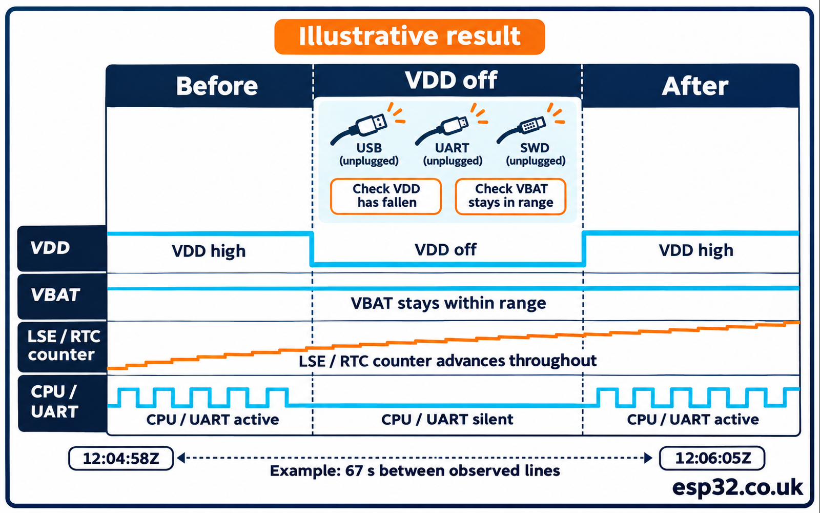
Now arrange a full loss of VDD. Record the last printed timestamp and the reference time of the cut. Disconnect main power and all external connections that could backfeed it, while leaving VBAT supplied. Confirm VDD falls and VBAT stays in range. Wait roughly one minute against an external clock, then restore main power and reconnect the receiving terminal. Account for the time required to restore the connection when comparing the first available line. A test record with t_before, t_after, and the externally measured elapsed time is more informative than simply ticking a box marked “retained”.
With a sound backup path, the timestamp after power returns will have moved forward by about the elapsed interval. If it returns to the seed or becomes unset, look for a reset of the backup domain, a low backup voltage or a board connection that tied backup power to the main rail. If the value survives but advances only while VDD is on, inspect the RTC source and test whether LSE really stayed running. These symptoms call for different fixes.
| Bench trial | Expected evidence | Useful observation if it fails |
|---|---|---|
| Powered for several seconds | Timestamp advances | Raw counter and LSE ready status |
| Press NRST | Date and seconds continue from previous run | Startup path, backup marker and source |
| VDD off for about one minute with VBAT present | Timestamp advances across the off interval | Measured VDD and VBAT, all cables disconnected |
| VDD and VBAT both removed on a disposable lab setup | Reporting build shows time unset after power returns | Remaining rail voltage and accidental provisioning |
The final trial is a deliberate loss-of-state test. Save any timestamp or calibration data you care about before removing both supplies. On boards with capacitors, allow time for the backup node to discharge and measure it. An apparently retained clock after unplugging both sources may simply have run from charge stored on the board. Reconnect the known safe backup supply, re-enable provisioning for one run and repeat the earlier tests if you need to restore the demonstration state.
Work through a retention measurement
Suppose the final serial line before you disconnect power reads 2026-01-01T12:04:58Z. Your reference clock records 67 seconds between that line and the first line you receive after reconnecting. The expected board timestamp is near 12:06:05Z. That elapsed time includes the time spent unplugging and reconnecting the terminal. If the board instead shows 12:05:03Z, only five seconds advanced. A plausible cause is a stopped backup oscillator, with those few seconds counted during the powered portions of the test. The voltages recorded during the cut help tell whether the crystal or the backup supply was responsible.
Make a second trial long enough to rule out hold-up from the board’s capacitors. Begin and end measurements at the same points each time. For example, use the capture time of the actual serial line instead of the moment you reach for a cable. Your reference may run at a different rate from the board, but over one minute the relevant distinction is between approximately one minute of progress and a handful of seconds. Leave long duration accuracy measurements for the next section.
Watch what happens if you deliberately set the initial time close to midnight on a valid test date. Starting at 2028-02-28T23:59:58Z should lead to 29 February, and the same experiment a year later should lead to 1 March. These tests show how the firmware translates the counter into a calendar after a date change. Reflash with the provisioning guard enabled only on a deliberately unset test domain, or invoke the setter from a separate explicit provisioning path. The supplied boot example will preserve a valid timestamp even when its seed is changed and recompiled.
You can also diagnose a low-half rollover without waiting for a particular wall-clock time. At one tick per second the low 16 bits wrap every 65,536 seconds, or 18 hours, 12 minutes and 16 seconds. With a valid test timestamp near a known boundary, inspect the two halves just before and just after the low word turns to zero. The high half should increase by one and the converted timestamp should progress by one second. The read procedure does not depend on the order in which the debugger shows the register values. Use the firmware’s serial result as the observation and treat debugger register snapshots as supporting evidence.
Use backup state as part of the logger design
If you save sensor data to flash or an SD card, consider what you want the logger to do while the RTC is unset. For example, append a sample number and an explicit invalid-time flag. When a trusted time becomes available, add a synchronisation record that identifies the first subsequent sample with valid UTC. This preserves earlier data for inspection without implying that its timestamps were established. A firmware update that changes the epoch or the interpretation of backup state should change the marker too, or migrate it deliberately.
If the logger must wake itself to collect a sample, distinguish standby with VDD available from a board whose main supply has been physically removed. VBAT supports the backup domain. The normal MCU and its sensors need main power for a measurement. A system that must restore main power on a schedule needs a supply design that can act on the wake signal. Test that power path independently of the software clock. Otherwise an RTC may keep perfect time through the cut while the logger remains unable to take a reading.
For a deployed device, store the time at the point where a sample is acquired, rather than when it happens to reach the terminal or storage driver. If readings are queued, keep timestamp and validity beside each sample. You can compare successive UTC timestamps with a sample sequence counter when debugging missed intervals. If elapsed time is the quantity you need for a control loop, use an appropriate timer or monotonic timebase. UTC can be corrected while the system is running, and a corrected timestamp can move in either direction.
Measure drift after retention works
If a clock gains two seconds over 24 hours, its average error is about 2 / 86400 × 1000000, or +23.1 ppm. A 20 ppm error corresponds to 1.728 seconds per day and roughly 52 seconds over 30 days. Use an external reference with known accuracy and measure the elapsed difference between two observations. An initial offset from pressing Reset or flashing the seed is an alignment error. Subtracting the first reading from the last makes it possible to estimate rate independently of that offset.
At one second display resolution, a short test will be dominated by quantisation. Even one second of measurement uncertainty over ten minutes is roughly 1,667 ppm. A longer run with consistent capture timing makes a useful bench measurement. Record temperature and whether the board was under main or backup power. Crystal tolerance, load capacitance and temperature contribute to real drift, and the enclosure may change thermal conditions compared with an open bench.
STM32F1 provides calibration through BKP_RTCCR. ST’s AN2604 describes removing pulses over a window of 1,048,576 clock cycles. One removed pulse per window is about 0.954 ppm, with a 7-bit setting that can slow a fast timebase. As an estimate with the nominal divider, a +23.1 ppm error corresponds to roughly 24 removed cycles per window. The resulting rate adjustment is about 22.9 ppm before the other sources of error. A slow clock needs a different approach, such as the prescaler offset and calibration method described by ST. Measure again after any change. ST AN2604, STM32F101xx and STM32F103xx RTC calibration
For a hardware frequency measurement, ST documents a calibration clock output derived from LSE, nominally 512 Hz with a 32.768 kHz reference divided by 64. Check the AN2604 procedure and the board connections before using PC13 for it. The usual Blue Pill LED circuitry may load that pin. An instrument connected directly to the oscillator pins can disturb the crystal and change the behaviour being measured. Start with the timestamp comparison and move to a dedicated test output if you need higher resolution.
Diagnose startup and backup failures
An LSE timeout means the ready flag failed to set within the software’s five second budget. Inspect whether the board really has a 32.768 kHz crystal connected to the two LSE pins. Verify the oscillator network against the manufacturer’s circuit and the STM32 hardware guide. Some crystals take longer to start under difficult conditions. Extending the timeout during diagnosis can help separate a slow start from no oscillation, but a product should log the condition and define what to do if the oscillator never starts. Switching silently to LSI changes the timebase and invalidates the backup test.
An RTC synchronisation timeout means you reached a different stage. Check that LSE is ready, RTCSEL selects LSE, and RTCEN is set. Confirm that the backup write gate was opened for the flag clear and that the normal HAL tick is running. A debugger breakpoint inside a tick-based loop can alter elapsed-time observations. Resume execution and capture the registers after the timeout. If you took over an existing project, inspect HAL_RCCEx_PeriphCLKConfig() call sites for clock selections and potential backup reset paths.
A write timeout points to RTOFF, which marks completion of a previous write. When the RTC clock is absent, a write handshake may fail to complete. Check the clock path before retrying. Repeatedly rewriting the marker to make the terminal look healthy defeats the validity check. Leave a failed timestamp unset and investigate the underlying power or clock problem.
If the terminal displays the wrong day at midnight, test the formatter using known raw values on both sides of the boundary. A Z timestamp describes UTC, so it may already be the next local day in one timezone and still the previous day in another. If the error occurs around February, verify the leap-year rule and field validation. If the timestamp jumps around a low-half rollover, check that the combined read uses a second high-half sample. The site’s STM32 timer lab offers a related example of handling counter boundaries, although its timer captures have a different purpose.
If a time jump affects a data logger, record that it happened. A corrected UTC clock can move backwards after manual setting. Give records a separate sequence number or an elapsed-time reference so you can reconstruct order later. Store timestamp validity and, where the application needs it, the last known synchronisation time as separate fields. A watchdog timeout can help recover firmware that stalls, while the RTC can preserve the time of that reset. These are independent jobs.
Extend the lab to scheduled measurements
The F103 RTC alarm compares the counter with a programmed value. In a simple logger, you can calculate a future epoch value for the next observation and check it against the supported range before arming an alarm. Add that feature after validating the continuous counter, as the alarm has its own write sequence, flag handling and interrupt routing. Consult RM0008 for the RTC alarm path and the constraints for your intended sleep or standby mode. Check that another alarm or HAL calendar helper does not rewrite the shared counter.
A useful first extension is to record the timestamp and temperature at the same moment, with a flag showing whether the timestamp is valid. The STM32 ADC guide provides the other half of that exercise. With a verified backup rail, a clock that keeps counting during power loss and a reproducible retention test, you can distinguish a missing sample from a reset and place each new sample on a consistent UTC timeline.