
A watchdog resets a microcontroller when firmware misses a deadline. To use one well, decide what work the application must complete before it earns another refresh. A periodic interrupt that keeps refreshing a watchdog can conceal a stalled foreground task. A refresh tied to observed progress gives the watchdog a way to detect that failure.
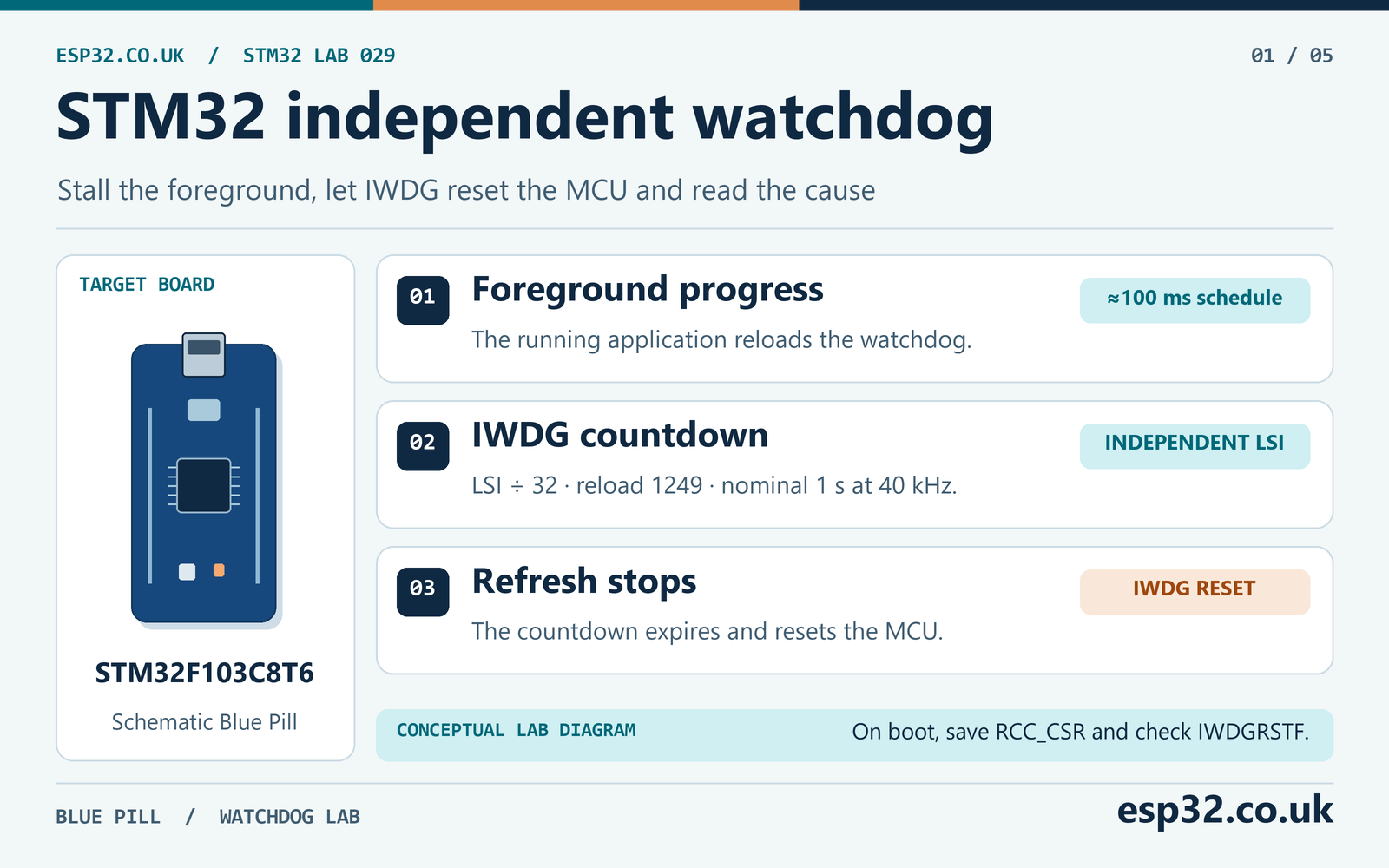
In this esp32PriceAliExpress price.co.uk/ guide, you will set up the independent watchdog on an STM32F103C8T6PriceAliExpress price Blue PillPriceAliExpress price, deliberately stall the foreground with a push button and confirm the reset source from the RCC flags. The lab uses a nominal one-second timeout and a 100 ms refresh interval. You will calculate the range caused by the LSI oscillator, read the boot evidence and see how the window watchdog imposes a different timing requirement.
Quick answer. In an STM32CubeF1 C project, start IWDG with HAL_IWDG_Init(), prescaler /32 and reload 1249. Refresh from the foreground while it is healthy. With this setup, the datasheet’s 30–60 kHz LSI range gives about 0.667–1.333 seconds from the last refresh. At startup, save RCC->CSR before clearing the reset flags, then check the saved IWDGRSTF bit.
Choose between the independent and window watchdogs
The STM32F103 has two watchdog peripherals. The independent watchdog, IWDG, uses the internal low-speed oscillator, LSI. The window watchdog, WWDG, uses PCLK1 through its own divider. Both can reset the MCU. Their clock sources and rules for a valid refresh make them suitable for different monitoring jobs. ST STM32F103x8/xB datasheet
| Feature | IWDG | WWDG |
|---|---|---|
| Clock on STM32F103C8 | Internal LSI | APB1 peripheral clock, PCLK1 |
| Main purpose | Detect a missed deadline | Detect a refresh outside a timing window |
| Refresh policy | Reload before timeout | Wait for the window, then reload before expiry |
| Counter configuration | 12-bit reload and prescaler | Seven-bit counter, window threshold and prescaler |
| Clock dependence | Can continue independently of the main clock | Timing follows PCLK1 while the peripheral runs |
| Reset evidence | RCC IWDGRSTF | RCC WWDGRSTF |
| Example in this article | Complete fault injection lab | Worked window calculation |
Start with IWDG if the first requirement is to recover from a stuck main loop. Use WWDG if an application must also detect a refresh that arrives too early, such as a faulty loop repeatedly servicing a watchdog ahead of schedule. Give each watchdog a named owner if you enable both. During commissioning, test one at a time so the reset source and timing are easy to interpret.
The watchdog restarts the microcontroller. Recovery still depends on the boot path and the rest of the circuit. An external sensor or radio that remains powered can stay in its previous state. If that device caused the hang, restarting the MCU alone may reproduce the failure. Plan how boot detects incomplete transactions and how it re-establishes a known hardware state.
Calculate IWDG timing from the LSI range
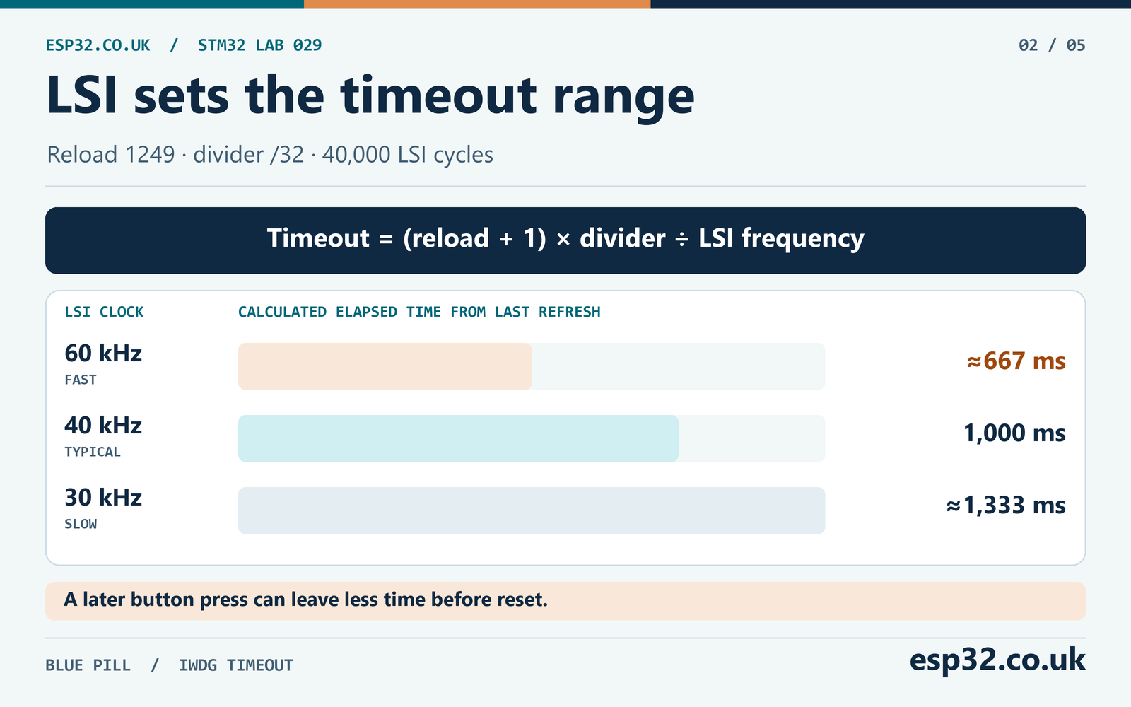
For a steady-state countdown after reload, the timeout is the number of counter ticks multiplied by the tick duration. The reload value represents one less than the number of ticks. At prescaler /32 and reload 1249, the watchdog gets 1,250 ticks and consumes 40,000 LSI cycles before expiry. Use the actual divider, such as 32, in the calculation. The prescaler register stores an encoding for that divider. ST RM0008, Independent watchdog chapter
tick_seconds = prescaler_divider / f_LSI_hz
timeout_seconds = (reload + 1) × tick_seconds
lab_timeout_seconds = 1250 × 32 / f_LSI_hz
DS5319 lists 30 kHz minimum, 40 kHz typical and 60 kHz maximum for the LSI under its stated conditions, with the frequency range evaluated by characterisation. Use the fast oscillator for the shortest watchdog deadline. Use the slow oscillator for the longest fault-detection time. A single room-temperature measurement can describe your test board, while the datasheet range is the starting point for a design budget. ST DS5319, Table 25
| LSI frequency | Counter tick with /32 | Timeout with reload 1249 |
|---|---|---|
| 60 kHz | About 0.533 ms | About 667 ms |
| 40 kHz | 0.800 ms | 1,000 ms |
| 30 kHz | About 1.067 ms | About 1,333 ms |
The table is for elapsed time from the most recent refresh. The lab button can be pressed anywhere between two refreshes, so the time from the button edge to reset can be shorter. If the loop normally refreshes every 100 ms, a press can arrive almost 100 ms into that countdown. Power-on, oscillator startup and reboot-to-first-output latency are separate from the steady-state calculation.
The largest permitted reload on this F1 IWDG is 4095. To choose a reload for a target number of milliseconds, multiply the target in seconds by the design oscillator frequency, divide by the prescaler, and account for the extra tick. Round according to your requirement and then recompute both the shortest and longest timeouts. If the result falls outside 0–4095, change the divider or revisit the requirement. The driver accepts /4, /8, /16, /32, /64, /128 and /256.
Make room for the worst legitimate refresh interval
The nominal 100 ms interval is a scheduling target. Firmware can miss it when interrupt work, a blocking peripheral call or another task delays the refresh path. The relevant measurement is the longest gap between successful reloads during legitimate operation. Measure that gap under the conditions that can actually occur together.
For example, an application might allow 100 ms between routine checks, 90 ms for one bounded transaction, 35 ms of scheduling delay and 25 ms of measurement margin. If these delays can accumulate, the budget is 250 ms. Against the shortest calculated timeout of about 667 ms, that leaves roughly 417 ms. These are example numbers. Real bounds come from your code, peripheral timeouts, clock range and workload.
There is also a recovery requirement. If your system needs to respond to a fault within one second, this configuration can miss that deadline at a slow LSI even before startup recovery time is added. Increasing the reload to avoid nuisance resets can make fault response too slow. Check the two ends of the timing range independently.
Turn a recovery requirement into a reload value
Suppose the longest legitimate refresh gap is 250 ms and the watchdog must expire within 750 ms after its last refresh. Let the programmed countdown consume a fixed number of LSI cycles. The fast 60 kHz case needs more than 15,000 cycles to survive 250 ms. The slow 30 kHz case allows at most 22,500 cycles to expire within 750 ms. Both requirements apply to the same reload and prescaler.
A /32 divider with reload 699 gives 700 ticks, or 22,400 cycles. The calculated range is about 373 to 747 ms, with 560 ms at 40 kHz. This meets the example bounds, but it leaves only about 3 ms on the slow end before the 750 ms limit. If the deadline includes additional uncertainty, choose a value with more room or revisit the design. Verify the measured boot time separately if the system must return to service by a deadline.
This method also exposes incompatible requirements. If the lower cycle bound is higher than the upper one, changing the prescaler cannot fix the conflict. Reduce the longest legitimate refresh gap, relax the maximum fault interval or select a watchdog and clock source that can meet the needed tolerance. The prescaler controls the granularity of available choices within the feasible range.
For real applications, budget boot and any update mode separately. A bootloader, a long peripheral reset sequence and a firmware update can have different progress checkpoints. If the hardware option starts IWDG automatically, those paths inherit the active watchdog. Establish how they prove forward progress and refresh before their own deadlines.
Wire the fault injection input and LED
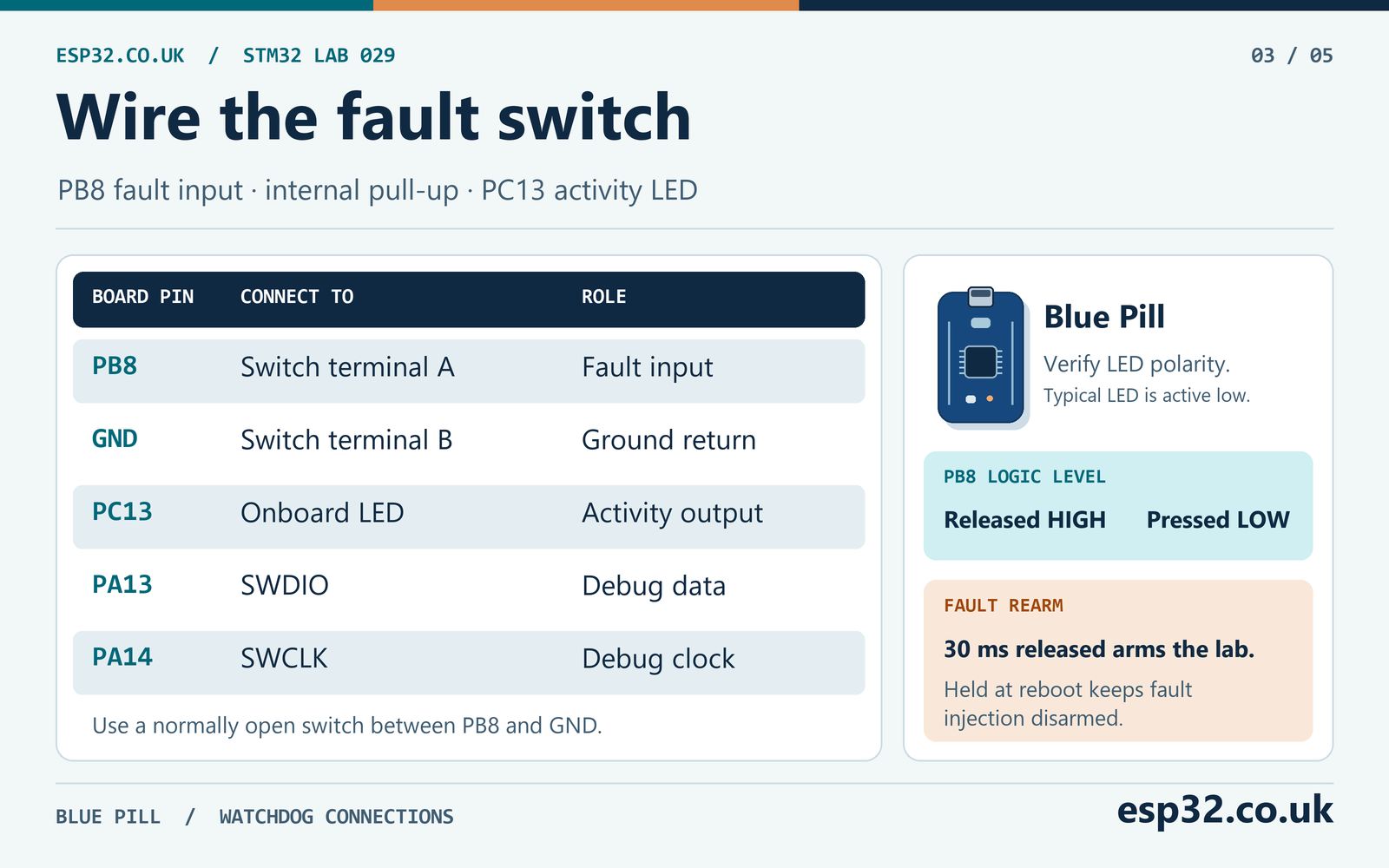
Use a Blue Pill with an STM32F103C8T6, an SWD programmer and a normally open push button. Connect one button terminal to PB8 and the other to GND. Configure PB8 as an input with an internal pull-up. The released level is high and the pressed level is low. The lab samples the pin in the main loop. An EXTI configuration from an earlier project is unnecessary.
| Connection or setting | Lab choice | Expected result |
|---|---|---|
| Button terminal A | PB8 input with pull-up | High when released |
| Button terminal B | Board GND | Press pulls PB8 low |
| Onboard LED | PC13 push-pull, initial high, low speed | Off initially on the typical active-low board |
| SWD | PA13 SWDIO and PA14 SWCLK | Flashing and debugger access |
| Optional analyser | PB8 and PC13, with common ground | Press and application activity visible |
Check the board’s LED routing and polarity. Many Blue Pill boards use an active-low LED on PC13. If yours differs, update the GPIO configuration and the lab’s output pin together. Start with the button released. If a four-leg switch appears permanently closed, identify the two separate contact groups with a continuity meter. STM32 GPIO and HAL LED tutorial
PB8 may already be reserved for another peripheral in your project. Use a fresh CubeMX configuration for the watchdog test or choose a free input and update the code. The earlier EXTI article explains the active-low button wiring and how to validate the pin level. This lab uses a short release qualification to avoid repeated resets if the switch stays held during reboot. STM32 EXTI and button debouncing tutorial
Configure STM32CubeMX for the software-started lab
Create an STM32F103C8Tx C project and retain Serial Wire debugging. Configure PB8 and PC13 as shown above. Leave the HAL timebase running in milliseconds. A normal working clock setup is sufficient, because IWDG timing comes from LSI. The main-loop scheduling still uses HAL ticks, so that timebase must advance.
Leave the IWDG peripheral unassigned in CubeMX for this example. The supplied module owns its handle and initialisation. Enable HAL_IWDG_MODULE_ENABLED in the HAL configuration and include the matching stm32f1xx_hal_iwdg.c in your build. A minimal generated project may omit the driver while the peripheral is disabled in the pinout tool. Use the same CubeF1 package as the rest of the project.
| Configuration | What to check |
|---|---|
| MCU | STM32F103C8Tx |
| PB8 | GPIO input, pull-up |
| PC13 | GPIO output push-pull, low speed, initial high for a typical board |
| Debug | Serial Wire |
| IWDG ownership | Application module, one initialisation |
| IWDG option byte | Software watchdog mode for this lab |
| HAL timebase | Running 1 ms tick |
Check the option bytes with the programmer if the board was previously configured for automatic watchdog startup. On the STM32F103, WDG_SW = 1 selects software watchdog mode and WDG_SW = 0 selects hardware watchdog mode. The lab assumes the former and requires no option-byte changes on a board already using it. A hardware-started watchdog can begin counting before the application reaches its intended start call. Keep the bootloader and option-byte configuration in scope when diagnosing early resets. ST PM0075, Flash programming and option bytes
In the reviewed CubeF1 driver, HAL_IWDG_Init() starts IWDG, enables access to the protected configuration registers, writes the prescaler and reload, waits for the update flags and refreshes the counter before successful return. The start forces LSI on. The software start key is 0xCCCC, the configuration unlock key is 0x5555 and the reload key is 0xAAAA. The lab uses the HAL functions for this sequence. ST HAL IWDG source v1.1.10
Add the watchdog lab to your application
Copy watchdog_lab.h into Core/Inc and watchdog_lab.c into Core/Src. The header declares the boot snapshot, the decoded IWDG flag, a refresh counter and a fault marker. These variables are available as debugger expressions. Their contents describe the current boot. The application fills the snapshot again from the hardware on every restart.
#ifndef WATCHDOG_LAB_H
#define WATCHDOG_LAB_H

#include "stm32f1xx_hal.h"

extern volatile uint32_t watchdog_lab_boot_csr;
extern volatile uint32_t watchdog_lab_iwdg_reset;
extern volatile uint32_t watchdog_lab_refresh_count;
extern volatile uint32_t watchdog_lab_fault_active;

void WatchdogLab_CaptureResetCause(void);
HAL_StatusTypeDef WatchdogLab_Start(void);
void WatchdogLab_Poll(void);

#endif
The lab refreshes from the foreground only. Every fifth refresh it toggles the LED, which gives roughly one transition per half second while the loop is responsive. The lab arms fault injection after PB8 has been observed released for 30 ms. Pressing it after arming stalls the foreground in a loop. The watchdog keeps counting because the stalled code performs no reload.
#include "watchdog_lab.h"
#include <stdbool.h>

#define REFRESH_INTERVAL_MS 100U
#define RELEASE_SETTLE_MS 30U
#define IWDG_RELOAD_VALUE 1249U

static IWDG_HandleTypeDef watchdog;
static uint32_t last_refresh_ms;
static uint32_t release_start_ms;
static bool release_observed;
static bool fault_armed;

volatile uint32_t watchdog_lab_boot_csr;
volatile uint32_t watchdog_lab_iwdg_reset;
volatile uint32_t watchdog_lab_refresh_count;
volatile uint32_t watchdog_lab_fault_active;

void WatchdogLab_CaptureResetCause(void)
{
    uint32_t boot_csr = RCC->CSR;
    watchdog_lab_boot_csr = boot_csr;
    watchdog_lab_iwdg_reset = (boot_csr & RCC_CSR_IWDGRSTF) != 0U;
    __HAL_RCC_CLEAR_RESET_FLAGS();
}

HAL_StatusTypeDef WatchdogLab_Start(void)
{
    watchdog.Instance = IWDG;
    watchdog.Init.Prescaler = IWDG_PRESCALER_32;
    watchdog.Init.Reload = IWDG_RELOAD_VALUE;

    HAL_StatusTypeDef status = HAL_IWDG_Init(&watchdog);
    last_refresh_ms = HAL_GetTick();
    return status;
}

void WatchdogLab_Poll(void)
{
    uint32_t now = HAL_GetTick();
    bool released = HAL_GPIO_ReadPin(GPIOB, GPIO_PIN_8) == GPIO_PIN_SET;

    if (!fault_armed) {
        if (!released) {
            release_observed = false;
        } else if (!release_observed) {
            release_start_ms = now;
            release_observed = true;
        } else if ((uint32_t)(now - release_start_ms) >= RELEASE_SETTLE_MS) {
            fault_armed = true;
        }
    } else if (!released) {
        watchdog_lab_fault_active = 1U;
        for (;;) {
            __NOP();
        }
    }

    if ((uint32_t)(now - last_refresh_ms) >= REFRESH_INTERVAL_MS) {
        (void)HAL_IWDG_Refresh(&watchdog);
        last_refresh_ms = now;
        ++watchdog_lab_refresh_count;
        if ((watchdog_lab_refresh_count % 5U) == 0U) {
            HAL_GPIO_TogglePin(GPIOC, GPIO_PIN_13);
        }
    }
}
Place the include in the generated Includes user section. Capture the reset flags near the start of main(), before other code that clears them. Start the watchdog after the generated clock and GPIO setup. Add the poll call to the body of the existing infinite loop. The following lines belong in separate locations in the generated project.
/* USER CODE BEGIN Includes */
#include "watchdog_lab.h"
/* USER CODE END Includes */

/* USER CODE BEGIN 1: first instructions inside main() */
WatchdogLab_CaptureResetCause();
/* USER CODE END 1 */

/* USER CODE BEGIN 2: after MX_GPIO_Init() */
if (WatchdogLab_Start() != HAL_OK) {
    Error_Handler();
}
/* USER CODE END 2 */

/* Inside the generated while (1) loop, in a USER CODE section */
WatchdogLab_Poll();
Call the start function once per boot. If initialisation fails, the watchdog may already be active, because the HAL starts it before waiting for the configuration update. Inspect the failure while bringing up the board and treat the error path as a boot failure. The lab module and the tagged HAL IWDG and GPIO drivers were compiled as Cortex-M3 objects. The full CubeMX firmware build and board test are separate steps.
The release qualification is a property of this demonstration. On the next boot, the static arming state starts clear. Holding PB8 low after a reset keeps fault injection disarmed while the watchdog resumes normal service. Release the button long enough to rearm, then press again. The 30 ms condition applies to the observed release. The first low sample after arming deliberately triggers the fault.
Read the reset flags before clearing them
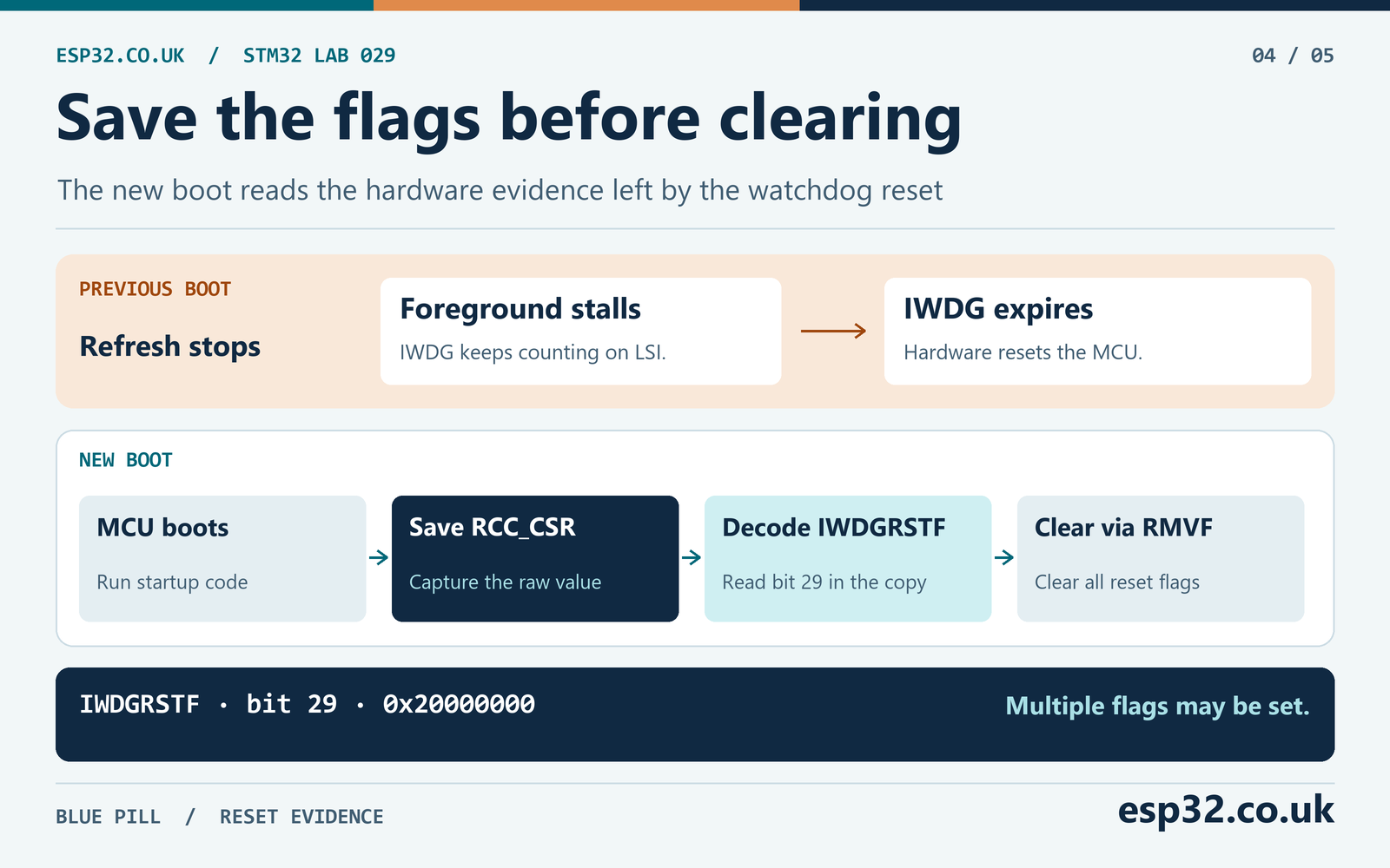
RCC_CSR holds several sticky reset flags. A flag can remain set across subsequent system resets until the flags are cleared, and multiple bits can be set at once. Read the register as early as the application can reliably do so, save the raw snapshot and clear the hardware flags afterwards. This separates evidence from the latest observed boot interval from older evidence already recorded by firmware. ST RM0008, RCC clock control and status register
| Snapshot bit | Event recorded |
|---|---|
| IWDGRSTF | Independent watchdog reset |
| WWDGRSTF | Window watchdog reset |
| SFTRSTF | Software reset |
| PORRSTF | Power-on or power-down reset |
| PINRSTF | Reset through NRST |
| LPWRRSTF | Low-power management reset |
This lab exposes the entire boot CSR value and a separate Boolean-style IWDG result. In the raw value, IWDGRSTF is bit 29, mask 0x20000000. The HAL clear macro writes the reset-flag removal control, RMVF. That action clears the reset flags as a group. If other components need the evidence, have them consume the saved copy instead of competing to read and clear the hardware.
Check bootloader behaviour if the snapshot seems to lose evidence. A bootloader can record and clear the flags before handing over to the application. The application then needs a documented handoff mechanism. The normal C startup code also reinitialises ordinary static variables. An in-RAM fault marker set just before the stall is useful for live observation, while the new boot gets the watchdog cause from RCC.
The reset flag describes the mechanism. It does not identify why the previous boot stopped making progress. For a field device, record useful progress or a failure code with a retention strategy that fits the hardware. Examples include a deliberately preserved RAM region with a validity check, backup registers where the board supports them, or a durable log with a bounded write path. Treat power loss, repeated resets and incomplete writes as separate cases.
Run the fault test and interpret the result
Flash the firmware through SWD and let it run normally. With PB8 released, check that the LED toggles and watchdog_lab_refresh_count increases. Wait at least 30 ms for the release to qualify. Press the button. The foreground stops refreshing, and after the remaining watchdog interval the board reboots. Observe the program after that boot without issuing another debugger reset.
| Test | Expected observation | What it checks |
|---|---|---|
| Released and running | LED toggles, refresh counter advances | Foreground refresh path |
| Press after release qualification | Fault marker sets and refreshes stop | Fault injection path |
| Observe the next boot | IWDG flag is 1 in the saved snapshot | Hardware watchdog caused reset |
| Keep PB8 held through boot | Normal refresh resumes, fault stays disarmed | Reboot handling |
| Release for at least 30 ms and press | Another fault can be injected | Release qualification and rearming |
| Reset deliberately by another mechanism | Inspect the saved flags for that boot | Difference between reset sources |
An LED pause by itself is ambiguous. Power problems, a stalled boot and a debugger halt can all stop the visible activity. Confirm the saved IWDG bit and examine the refresh count after the restart. A direct test can record PB8 and a dedicated boot marker on a spare GPIO, with common ground. Toggle the marker early after initialising the pin and account for the code that runs before it. The time from PB8 to the marker includes both the remaining watchdog interval and boot latency.
The STM32F1 has debug controls for watchdog operation while the core is halted. A freeze setting can pause IWDG during breakpoints. Without it, the watchdog can expire while you are inspecting code. For a timing test, run continuously and use a logic analyser or read the post-reset variables without inserting a halt during the countdown. Check the debugger’s reset and freeze settings if the standalone behaviour differs.
If you need serial diagnostics, print the saved reset flags after the UART is ready and keep the print path bounded. A boot message that blocks long enough can itself miss a watchdog deadline. Use the prior UART guide for setup and keep the boot snapshot independent of the logging transport. STM32 UART with HAL, interrupts and DMA
Check what is still running during the fault
The injected loop stops foreground progress but leaves interrupt delivery unchanged. If a debugger can observe variables without halting the target, the HAL tick may keep increasing while the refresh count stops. This is the failure that an unconditional refresh in the tick interrupt would miss. On another application, a DMA engine or timer output can also continue while its consumer is stuck. Choose the progress signal that represents completed work rather than the mere presence of peripheral activity.
Repeat the held-button test once with the switch released shortly after the stall, and once with it held through the reboot. In both cases the fault loop should run until the watchdog resets the MCU. Releasing the button cannot exit the loop. After reboot, a held input must stay disarmed until it has been released for the qualification period. That checks the intended difference between the injection condition and the recovery condition.
Use a short lead and a clean switch signal for the bench experiment. The armed detector intentionally accepts the first observed low, so noise on PB8 can inject a fault. A deployed product that uses a physical input for recovery or maintenance needs a qualification policy appropriate to that input.
Refresh only when the required work has progressed
The demo ties refresh to a foreground loop to make a single failure easy to reproduce. A real application may have several required activities. A task can still be scheduled while its useful work is stuck. For example, a sensor thread can keep retrying a broken transaction while the application receives no valid data. Define the milestone that proves progress for each activity.
One design records a monotonically changing progress counter for every required worker. Each worker advances its counter after completing the relevant operation or entering an explicitly accepted idle state. The watchdog owner compares those counters with the previous observations and checks their deadlines. It refreshes only when the required workers have progressed within their allowed windows.
Avoid keeping a permanent “healthy” flag that is set once at startup. Check the freshness of the observation. For a worker that legitimately sleeps for long periods, define the expected idle state and its next deadline rather than requiring a fake heartbeat. The watchdog budget should reflect when work is due and what valid completion looks like.
On an RTOS, account for scheduling priority and shared state when exchanging health information. A high-priority service task may run even while a lower-priority worker is starved. Place the reload decision where it has a coherent view of worker deadlines. Under load, measure the time between successful refreshes and the time to recover from each injected failure.
Recovery is also a design decision. A repeatable reset may indicate a persistent problem, such as a peripheral that is still in a bad state. Consider which outputs need a safe startup state and how repeated failures affect system behaviour. Keep a limited diagnostic path and avoid a restart loop that continuously repeats a harmful operation. The bench lab has a simple example of recovery gating because it waits for release before the same input can inject another fault.
Test the failures that matter to the application
Once the button test works, list the activities a watchdog should supervise and define a way to stall each one on purpose in a test build. A useful fault test produces a known absence of progress without relying on power removal or a debugger breakpoint. It then checks both the reset cause and the state the application reaches on the next boot. Keep the fault injection under an explicit test control so normal operation cannot enter it by accident.
| Injected condition | Evidence to check before recovery | Expected behaviour to define |
|---|---|---|
| Foreground stuck while interrupts run | Main-loop milestones stop | Watchdog expires despite continued interrupt activity |
| Worker blocked waiting for a device | Other workers still progress | Missing worker deadline blocks refresh |
| Device reports a bounded failure | Error path completes and reports failure | Application enters its chosen degraded mode |
| Long but valid burst of work | Successful reloads remain within budget | No nuisance reset |
| Same boot failure repeats | Reset cause and restart count are recorded | Boot reaches the selected recovery path |
A worker can complete an operation with an error and still make progress. For example, a sensor driver can time out, release its bus resources and publish a fault state. That differs from a transaction that never returns. Decide whether operating without that sensor is valid for the application. A healthy-progress check can allow a defined degraded mode while still detecting a blocked worker.
Exercise legitimate slow operations as well as faults. If the monitor only sees clean short transactions during testing, a rare combination of bus retries and interrupt load can create a surprise reset later. Log the largest measured refresh gap and the expected clock assumptions. If the target has a separate bootloader, repeat the tests with the exact production startup order and check which stage owns the first refresh.
Calculate a WWDG refresh window
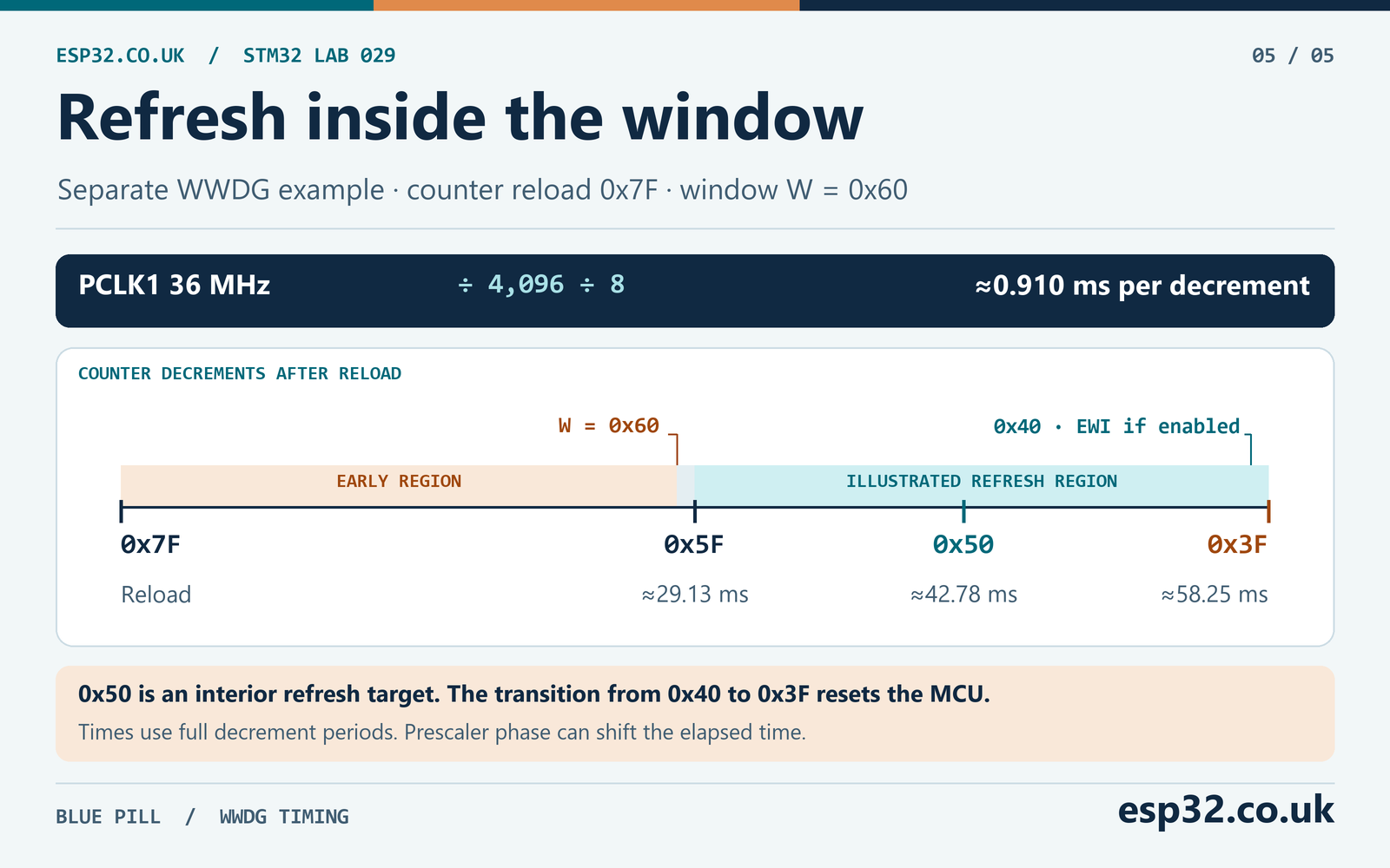
The F103 window watchdog decrements once every 4096 × prescaler PCLK1 cycles, where the available prescaler values are 1, 2, 4 and 8. Its lower boundary is the transition from 0x40 to 0x3F, which causes a reset when enabled. An early reload can also reset the MCU when the counter is above the configured window. Plan to refresh strictly inside the window, with margin on both sides. ST RM0008, Window watchdog chapter
As a worked example, use PCLK1 of 36 MHz, divider /8, initial counter 0x7F and window register 0x60. One decrement takes about 0.910 ms. From 0x7F it takes 32 decrements to reach 0x5F, which is strictly below the window register. It takes 64 decrements to reach 0x3F. An interior target of 0x50 is 47 decrements after reload. This is a separate calculation from the IWDG lab.
| Point in the example | Counter | Decrements since 0x7F | Full-tick time equivalent |
|---|---|---|---|
| Reload | 0x7F | 0 | 0 ms |
| First count strictly below W | 0x5F | 32 | About 29.13 ms |
| Example refresh target | 0x50 | 47 | About 42.78 ms |
| Early wakeup interrupt point | 0x40 | 63 | About 57.34 ms |
| Reset if no valid refresh | 0x3F | 64 | About 58.25 ms |
The times in the table are full-tick equivalents. The free-running prescaler may be partway through its cycle when the counter is reloaded, so real time to a count can differ by up to about one decrement period. Interrupt and scheduling jitter also matter. Choose a point with margin and validate on the actual clock configuration. Use PCLK1 itself, without applying the APB timer multiplier used by TIM peripherals. STM32 timers and APB clock tutorial
An early wakeup interrupt can run at 0x40 if configured. There is only one decrement from that point to the reset threshold. Treat it as a short opportunity for a bounded diagnostic or another carefully designed action. It is not a suitable place to start a long flash erase or wait on a serial transaction. If it unconditionally refreshes, it can also undermine the progress check you intended the watchdog to enforce.
Troubleshoot watchdog behaviour on the Blue Pill
| Symptom | First check | Possible cause |
|---|---|---|
| Board resets immediately after flash | Saved RCC flags and option bytes | Watchdog starts during boot or initialization stalls |
| Button does nothing | PB8 level and release qualification | Wrong switch legs, pin mode or held input |
| LED stops but no reset follows | Debug freeze and actual IWDG start | Core halted with freeze active or watchdog never enabled |
| Watchdog resets despite periodic service | Longest reload gap and LSI range | Legitimate worst-case work exceeds the shortest timeout |
| Reset occurs and LED stays off | PC13 route and boot progress | Different board LED or another startup fault |
| IWDG flag seems to stick across tests | Save and clear order | Older reset flags were left set |
| Prescaler or reload update stalls | IWDG_SR and APB clock | Update flags fail to clear under an errata condition |
| WWDG resets after a refresh call | Window, PCLK1 and current count | Refresh arrived too early or too late |
If the board resets before you can debug, connect using the programmer’s supported reset connection procedure. Check the existing option bytes and boot code before making changes. Preserve a known working image for recovery. A short timeout can make repeated attempts to attach during normal execution difficult.
ST’s ES096 describes cases where the IWDG prescaler and reload update flags can remain set at low APB clock rates. It also covers a Stop-mode sequence where entering Stop immediately after writing the registers can prevent the flags from clearing. Keep the relevant APB clock higher than twice the watchdog clock as documented and wait for the update flags before entering Stop after writes. This foreground lab assumes normal Run mode. A low-power project needs its own watchdog and wake-up timing analysis. ST ES096, IWDG errata
When comparing bench results, record the exact board, firmware build, supply, clock configuration, option bytes and debug settings. If one run shows an unexpected reset, keep the raw CSR snapshot instead of clearing it during diagnosis. Compare what the application observed with the fault you actually injected. That makes it easier to distinguish an electrical reset, an IWDG deadline and a WWDG window violation.
Common STM32 watchdog questions
Can firmware stop IWDG after it starts?
On this STM32F103, software can reload an active IWDG. Once started, it cannot normally be disabled by software until reset. A debugger freeze setting can pause it during a halt. Treat that as a debug condition when interpreting a bench test.
Does a faster CPU clock make IWDG expire sooner?
The IWDG countdown comes from LSI and its prescaler. A CPU clock change can affect application execution and the scheduling of refreshes, but it does not directly set that countdown rate. WWDG depends on PCLK1, so APB1 clock changes affect its window timing.
Should I refresh the watchdog in SysTick?
For this lab, the foreground owns refresh because it is the activity being tested. If SysTick refreshes unconditionally while a foreground loop is stuck, the injected failure can go undetected. A supervisor using a periodic timer can work when it checks fresh evidence from each required activity before reloading.
Can I reuse these settings on another STM32?
Recalculate from the device’s oscillator data, timer fields and watchdog features. Some newer parts offer different prescalers, IWDG windows or low-power controls. Use the reference manual, datasheet and HAL for the exact chip. Start by verifying the intended reset source with a controlled fault.