
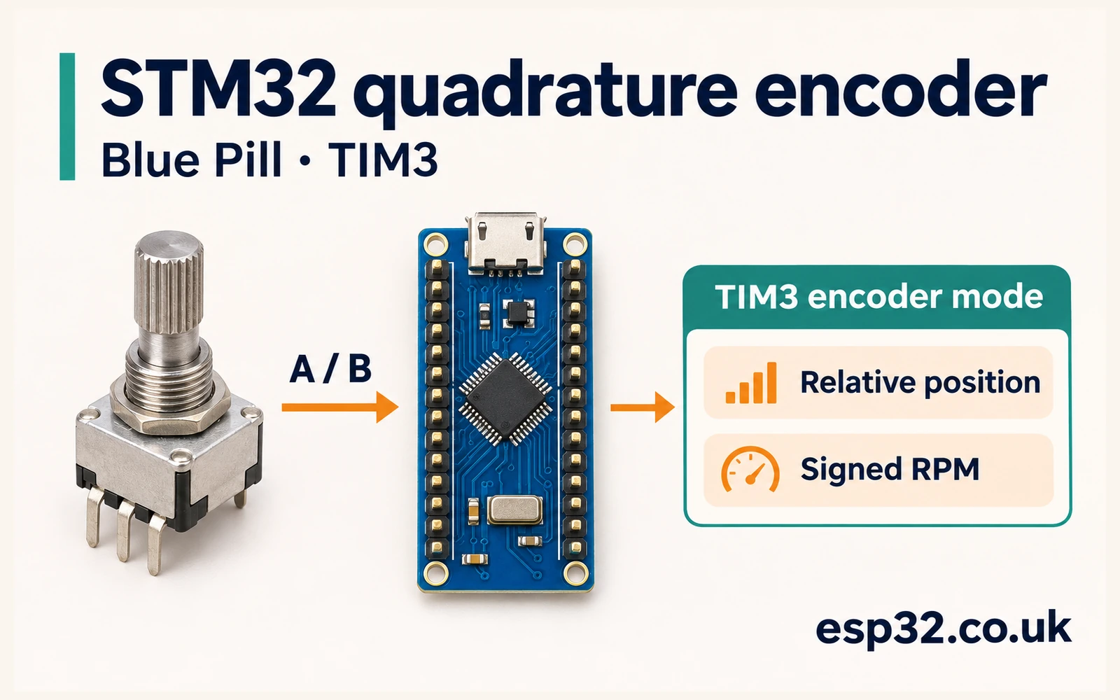
An STM32F103C8PriceAliExpress price Blue PillPriceAliExpress price can count quadrature encoder transitions in hardware. Connect the encoder’s A and B outputs to TIM3 channels 1 and 2, set the timer to encoder mode, and read its counter periodically. TIM3 handles the phase decoding while the application uses successive readings to calculate relative position and signed RPM.
In this esp32PriceAliExpress price.co.uk/ guide, you'll wire a 3.3 V-compatible encoder, set the STM32Cube HAL parameters and test both directions. The lab leaves TIM3 running across its 16-bit wrap. It samples the counter on a nominal 100 ms schedule, measures the actual interval, and flags cases where it can no longer trust the accumulated position.
Quick answer. Use PA6 for TIM3_CH1 and PA7 for TIM3_CH2, with TIM3 remapping disabled. Choose encoder mode TI12, period 65535 and matching input filters on both channels. Start both channels with HAL_TIM_Encoder_Start(&htim3, TIM_CHANNEL_ALL). Convert the change in CNT to a signed delta modulo 65,536 and divide by your measured counts per revolution and elapsed time to obtain RPM.
Choose and wire a quadrature encoder
Use a Blue Pill with a working SWD connection, a passive mechanical quadrature encoder or a compatible powered encoder, and short leads. A logic analyser can show the two phases together. A knob with a marked shaft or a removable pointer helps you count complete turns. You can start with the debugger alone and add a serial display later.
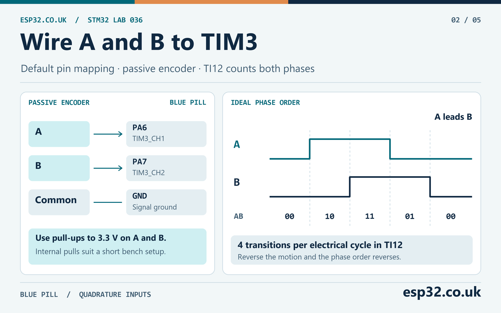
For a passive encoder, identify A, B and the common terminal from the part drawing or a continuity test with power disconnected. Connect common to ground and pull A and B to 3.3 V. The contacts then pull the input low as the shaft moves. Internal pull-ups work as a starting point for a short bench setup. External 10 kΩ pull-ups to 3.3 V are another option for a passive encoder on short leads. Verify the actual levels and transitions at the MCU. Some knobs have a separate push switch. Its two terminals are independent of the encoder phases.
| Encoder connection | Blue Pill connection | Purpose |
|---|---|---|
| A | PA6, default TIM3_CH1 | Phase A input |
| B | PA7, default TIM3_CH2 | Phase B input |
| Passive common or encoder signal ground | GND | Common reference |
| Pull-up supply for passive or compatible open-drain outputs | 3.3 V | Define the released logic level |
| Powered encoder VDD | Supply specified by the encoder manufacturer | Power the encoder if required |
Use the electrical interface specified for a powered encoder. A 3.3 V push-pull output can drive a compatible STM32 input with a common ground. An open-collector output needs a pull-up and must allow the chosen pull-up voltage. A differential A+/A− and B+/B− encoder needs a compatible differential receiver with logic outputs suitable for the STM32. Keep higher-voltage logic and motor supply wiring away from PA6 and PA7. Those pins also serve analogue functions and must be treated according to their actual ratings. Blue Pill GPIO voltage and tolerance guide
The default mapping shares PA6 and PA7 with SPI1 MISO and MOSI. It also uses the same TIM3 channels that other firmware could configure for output. Give those pins and TIM3 one job in this lab. Inspect the CubeMX pinout and the actual board headers before connecting the encoder. The Blue Pill pinout guide and the STM32 SPI1 wiring guide show how these alternate uses overlap.
Read the phase order
An incremental quadrature encoder produces two signals with an offset in phase. For an ideal cycle with A leading B, the states written as AB can be 00 → 10 → 11 → 01 → 00. Reverse the direction and the state order reverses. The diagram starts at 00 for convenience. A physical encoder can be resting in any of the four states when you power up.
In TI12 encoder mode, TIM3 uses a transition on either input and the level of the other input to update its count. One electrical cycle produces four transitions in this mode. The hardware counts up for one phase order and down for the other. Which physical direction you call positive depends on how you connect A and B and view the shaft. Mark a direction, move the shaft slowly and observe the sign. Swapping A and B reverses the sign. An application can also define its sign convention when it publishes the result.
| TIM3 encoder mode | Transitions used | Counts per ideal electrical cycle |
|---|---|---|
| Single-phase counting, mode 1 or 2 | Both edges of the selected phase, direction derived from the other phase | 2 |
| Mode 3, TI12 | Both edges on both inputs | 4 |
Use mode 3 for the lab. At power-on, the encoder can only report relative motion from the starting state. Absolute position needs a known reference, such as homing the mechanism or observing an index with a suitable capture scheme.
Configure TIM3 encoder mode in STM32CubeMX
Create a C project for the STM32F103C8 and leave Serial Wire debugging enabled. For a simple bench clock, use HSI at 8 MHz with AHB and APB1 undivided. Select TIM3 Encoder Mode under the timer’s mode settings and use the default pins. CubeMX versions can present the labels differently. Check the generated HAL_TIM_Encoder_Init() configuration and the GPIO setup to confirm what was applied. STM32CubeMX and CubeIDE setup guide
| Parameter | Lab setting | What it controls |
|---|---|---|
| TIM3 remap | Disabled | PA6 and PA7 carry channels 1 and 2 |
| Encoder mode | TI12, mode 3 | Decode both phases at x4 |
| Timer prescaler | 0 | Keep the lab at the unprescaled configuration |
| Counter period ARR | 65535 | Full 16-bit modulo, with 65,536 possible values |
| Clock division CKD | DIV1 | Set the input filter’s timing base |
| Input selection | Direct TI on both channels | Use the corresponding phase pin for each channel |
| Input polarity | Rising on both channels in HAL | Select non-inverted input polarity |
| Input capture prescaler | DIV1 on both channels | Use the undivided input configuration |
| Input filters | 15 on both channels | Sample at fDTS ÷ 32 and require eight consecutive samples |
| GPIO pulls | Pull-up for the passive contact example | Keep released inputs high |
| TIM3 interrupt and DMA | Disabled in this lab | Foreground reads the hardware counter |
CubeMX may show an initial counter mode of Up in the timer base parameters. In encoder mode, the phase relationship controls the running direction. The channel polarity setting labelled Rising corresponds to non-inverted input polarity. Mode TI12 still counts both edges of both filtered inputs. Check both channel enables after HAL_TIM_Encoder_Start(). The TIM3 clock, the pin input path and the timer counter all need to be active for motion to appear in CNT.
The timer only moves when it sees qualifying phase transitions. At standstill the counter should remain steady. The APB timer clock is still relevant to input synchronisation and the digital filters. At 8 MHz with APB1 undivided, the TIM3 clock is 8 MHz. On a common 72 MHz configuration with APB1 divided by 2, the bus clock is 36 MHz and the TIM3 timer clock is 72 MHz. Use the clock tree actually generated for your board. STM32 timer clocks, PWM and input capture
Set the input filter from the shortest valid level
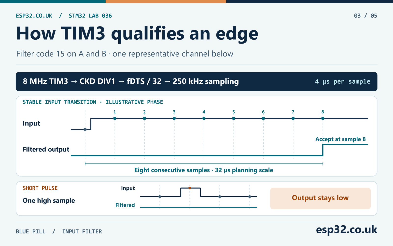
The input filter uses consecutive digital samples to accept a transition. Its setting selects a sampling frequency and a number of samples. For code 15 on TIM3, the sampling clock is fDTS ÷ 32 and the required run is eight consecutive samples. With CKD set to DIV1 at an 8 MHz timer clock, fDTS is 8 MHz. The filter samples at 250 kHz, one sample every 4 µs. Eight sample periods are 32 µs. The edge can arrive at different points between sample instants, so use 32 µs as a filter planning scale and leave margin for real signals.
| TIM3 clock and filter | Sample rate | Eight-period time scale |
|---|---|---|
| 8 MHz, CKD DIV1, filter 15 | 250 kHz | 32 µs |
| 72 MHz, CKD DIV1, filter 15 | 2.25 MHz | About 3.56 µs |
| 8 MHz, filter 3 using the timer clock directly | 8 MHz | 1 µs |
The last row shows how a smaller filter setting can help clean high-rate inputs. It will pass shorter disturbances too. Keep both phase filters matched so the signals see similar qualification timing. Measure the shortest high and low levels and the minimum separation between A and B edges at the fastest expected speed. If the waveform is nearly a square wave, a level lasts about half the period of that channel. Duty-cycle distortion, cable effects and phase skew can reduce the available margin.
Mechanical contacts can bounce for longer than the filter’s time scale. You may see small back-and-forth changes while turning slowly or stopping on a contact boundary. Measure both channels at the MCU before increasing the filter or adding hardware conditioning. A front end that delays one phase much more than the other can change the order that TIM3 sees. The EXTI and button debouncing guide covers why a clean-looking switch press can contain several transitions.
Extend the 16-bit counter into a signed position
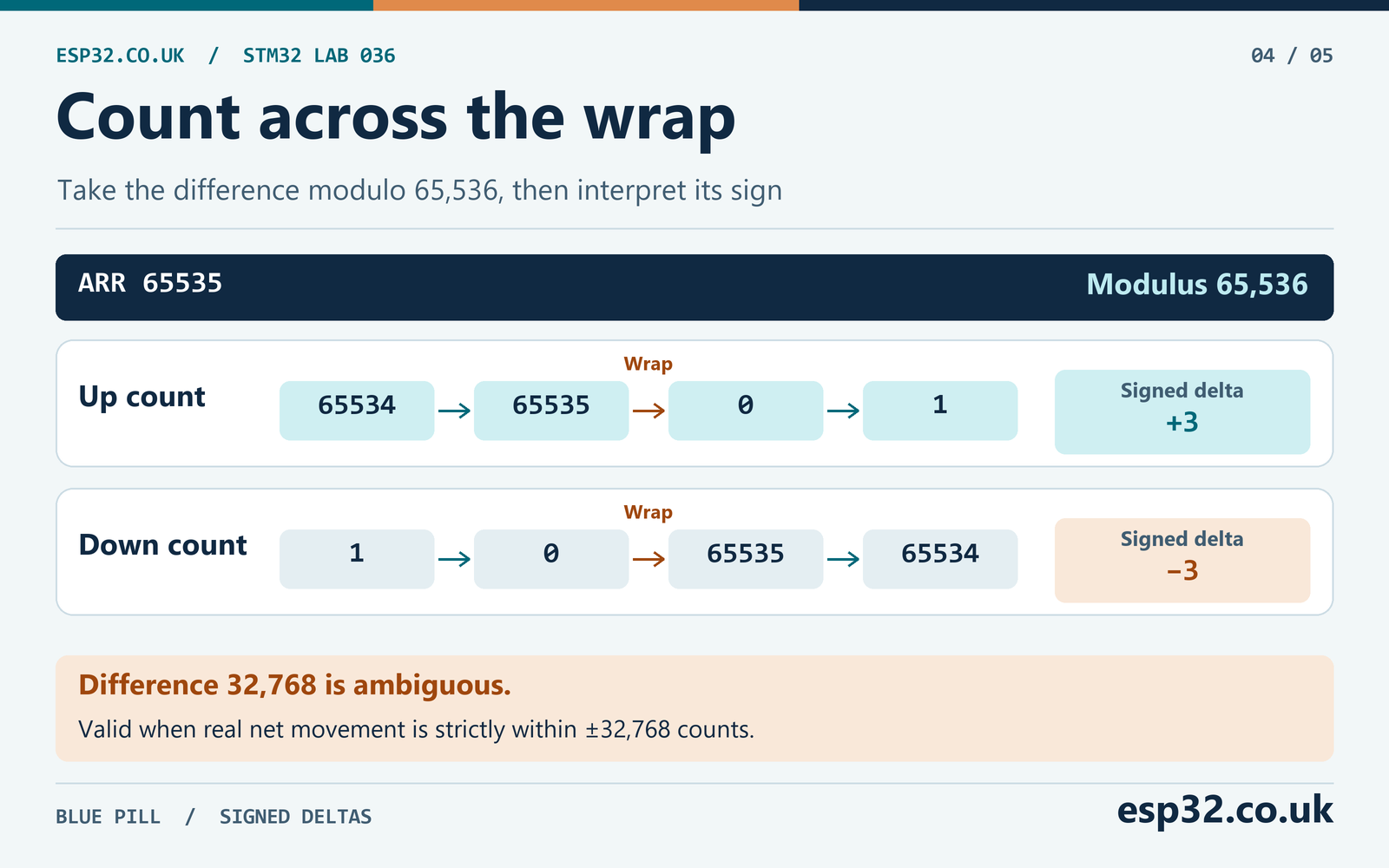
TIM3 wraps from 65535 to zero when it counts up, and from zero to 65535 when it counts down. A forward move from 65534 to 1 is three counts. Subtracting the two values as ordinary signed integers gives the wrong interpretation at the boundary. Compute the difference modulo 65,536 first. An unsigned 16-bit result gives the correct wrapped difference for ARR 65535.
To interpret that unsigned result, use the half-range rule. Values 0 through 32767 are nonnegative changes. Values above 32768 are negative changes and can be converted by subtracting 65,536. Exactly 32768 has two equally short interpretations, so the lab rejects it. The arithmetic is valid when the actual net change between readings is strictly between −32768 and +32768.
| Previous CNT | New CNT | Unsigned difference | Interpreted delta |
|---|---|---|---|
| 100 | 107 | 7 | +7 |
| 107 | 100 | 65529 | −7 |
| 65534 | 1 | 3 | +3 |
| 1 | 65534 | 65533 | −3 |
| 1000 | 33768 | 32768 | Ambiguous |
Two counter samples cannot reveal additional complete wraps or tell which direction crossed the half-range when the movement was larger. For example, a real forward change of 40,000 gives an unsigned difference of 40,000. The half-range interpretation would report −25,536. A sample that looks plausible can therefore be wrong if the operating assumptions are violated. Pick the longest sampling gap using the fastest credible rate of transitions at the timer, including margin for noise or speed overshoot.
The lab’s 300 ms maximum accepted interval is designed around a ceiling of 100,000 counts per second. Under that assumption 300 ms covers at most about 30,000 counts, with room below 32,768 even for millisecond tick quantisation. This is a software unwrapping budget. It does not rate the filter or hardware input for 100,000 counts per second. A lower input rate can still overrun the software budget if the application stops calling the poll function. Avoid long foreground waits and check both timing limits.
If a window is rejected, the code still updates its baseline to the newest reading. The next valid window can report speed again. The old cumulative position stays marked invalid because the motion during the rejected window is unknown. Zeroing the software position starts a new reference and takes a fresh count and timestamp. Keep the shaft at the intended reference point during that operation.
Measure counts per revolution and convert to RPM
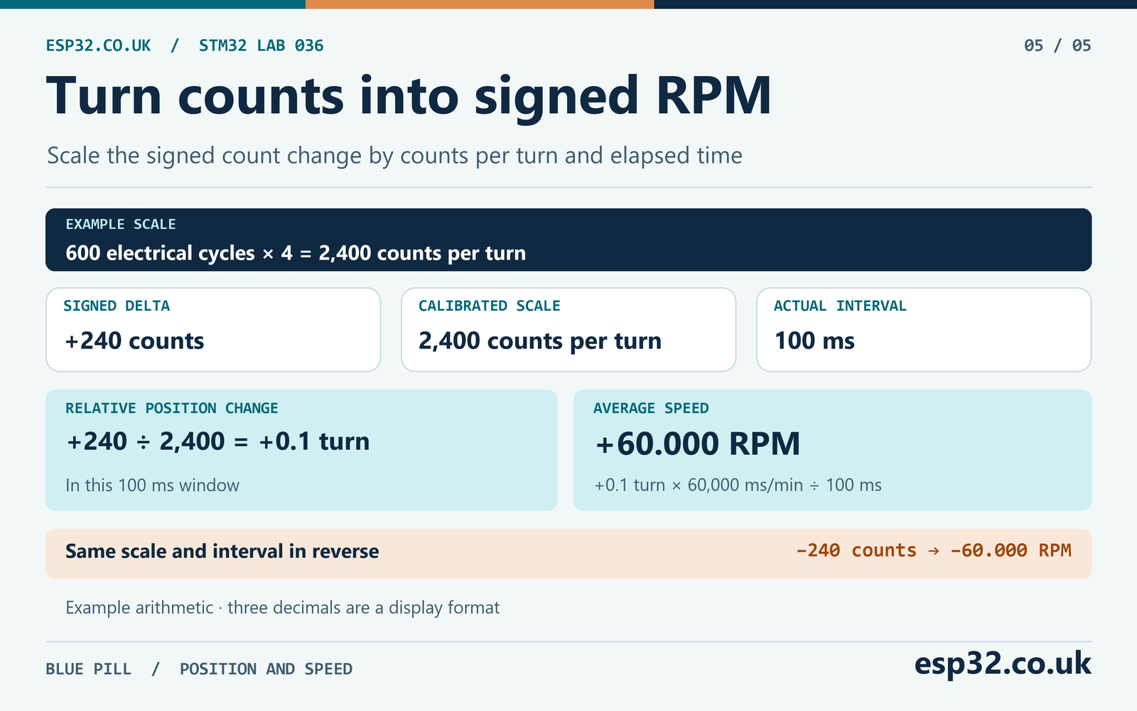
Find the number of decoded counts per revolution of the shaft you care about. Encoder manufacturers use terms such as PPR, CPR, cycles and pulses in different ways. Read what the number describes before applying a multiplier. An encoder with 600 electrical cycles on channel A per shaft revolution yields 2,400 counts at x4. If a specification already gives 2,400 decoded counts per revolution, use that value directly. Detents are the mechanical clicks and may not correspond to one complete electrical cycle each.
For an unknown encoder, mark the shaft and housing. With the power on and the programme running, zero the software position at the mark. Turn several full revolutions in one direction and return to the same mark. Divide the magnitude of the accumulated change by the number of revolutions. Repeat in reverse. If both results agree, use the measured value for the RPM calculation. If they differ, examine phase order, missed transitions, contact bounce and repeatability of the endpoint. Extra revolutions reduce the effect of being one count away from the intended mark.
If the encoder is upstream of gearing, name the shaft you measure. An encoder on a motor shaft with 2,400 counts per motor turn and a 5:1 reduction gives 12,000 counts per output turn under an ideal rigid ratio. Use 2,400 to report motor RPM or 12,000 for output RPM. Backlash can produce motor counts before the output moves during a reversal. Referencing the motor encoder alone can only infer the output’s position through that mechanical relationship.
The speed calculation uses the count delta and measured elapsed milliseconds. Divide by counts per turn to get turns during the interval, then multiply by 60,000 ÷ elapsed_ms to get revolutions per minute. The code keeps three decimal places as an integer. It computes rpm_milli = delta × 60,000,000 ÷ (counts_per_turn × elapsed_ms) with 64-bit intermediates. A value of −60000 means −60.000 RPM. Integer division truncates towards zero.
| Counts per turn | Count delta | Actual interval | Signed result |
|---|---|---|---|
| 2,400 | +240 | 100 ms | +60.000 RPM |
| 2,400 | −240 | 100 ms | −60.000 RPM |
| 2,400 | +120 | 102 ms | +29.411 RPM after truncation |
| 2,400 | +1 | 100 ms | +0.250 RPM |
| 48 | +1 | 100 ms | +12.500 RPM |
Three decimal places describe the format of the result. The measurement resolution follows the count scale and time window. With a 48-count encoder, one count at 100 ms is already 12.5 RPM. At a low steady speed, one window may contain a count while the next has none. Averaging more windows can reduce the variation but increases the time it takes to see a change. A separate period measurement using known edges is another approach for very low rates.
The reported value is net average speed during the window. Moving forward and then back by the same number of counts gives a result of zero. If the application needs the path travelled or the peak speed during rapid reversals, use more frequent observations or a capture method designed for that quantity.
Balance slow-speed resolution against the sampling gap
For a 48-count encoder, changing the window from 100 ms to 200 ms reduces the speed increment per count from 12.5 RPM to 6.25 RPM. It also doubles the time before a new value is available. The maximum gap still needs to fit the unwrapping limit. At 100,000 counts per second, a 300 ms indicated window plus one millisecond of tick quantisation can contain about 30,100 counts. A 400 ms window at that same rate could contain 40,000 counts, outside the half-range. If you change the sample constants, check the worst credible rate and gap together.
You can keep the 100 ms polling window and compute a slower display value from several valid samples. Sum the signed deltas and elapsed milliseconds, then apply the RPM formula to those sums. This weights each sample by its duration when the poll intervals vary. Clear the averaging window after a rejected sample, so the displayed average covers a continuous known interval. Position updates can keep their faster cadence while the display shows a steadier value.
Time also contributes to measurement error. A one-millisecond uncertainty is about one percent of a 100 ms window before considering encoder quantisation or oscillator tolerance. For a calibrated measurement, use a known time reference and compare against a full-turn test at the operating speed. Keep the number of displayed digits consistent with the test evidence.
Add the HAL encoder lab
Keep the standard HAL millisecond timebase enabled. Add encoder_lab.h and encoder_lab.c to the generated project and build as C11. Call EncoderLab_Start() after MX_TIM3_Init() and pass the measured counts per turn. The module checks the timer instance, period and counts-per-turn argument before starting both encoder channels. It takes its first reference once the timer is running.
#ifndef STM32_036_ENCODER_LAB_H
#define STM32_036_ENCODER_LAB_H

#include "stm32f1xx_hal.h"
#include <stdbool.h>
#include <stdint.h>

typedef struct {
    int64_t position_counts;
    int64_t rpm_milli;
    int32_t delta_counts;
    uint32_t elapsed_ms;
    uint32_t rejected_windows;
    uint16_t raw_count;
    bool position_valid;
    bool speed_valid;
} EncoderLabStats;

extern volatile EncoderLabStats encoder_lab_stats;

bool EncoderLab_Start(TIM_HandleTypeDef *timer, uint32_t counts_per_turn);
void EncoderLab_Poll(void);
void EncoderLab_Zero(void);

#endif
#include "encoder_lab.h"
#include <stddef.h>
enum { SAMPLE_MS = 100, MAX_WINDOW_MS = 300 };
volatile EncoderLabStats encoder_lab_stats;
static TIM_HandleTypeDef *encoder;
static uint32_t counts_per_turn;
static uint32_t previous_ms;
static uint16_t previous_count;
void EncoderLab_Zero(void)
{
if (encoder == NULL) {
return;
}
previous_ms = HAL_GetTick();
previous_count = (uint16_t)__HAL_TIM_GET_COUNTER(encoder);
encoder_lab_stats.raw_count = previous_count;
encoder_lab_stats.position_counts = 0;
encoder_lab_stats.delta_counts = 0;
encoder_lab_stats.elapsed_ms = 0;
encoder_lab_stats.rpm_milli = 0;
encoder_lab_stats.position_valid = true;
encoder_lab_stats.speed_valid = false;
}
bool EncoderLab_Start(TIM_HandleTypeDef *timer, uint32_t turn_counts)
{
if (encoder != NULL || timer == NULL || timer->Instance != TIM3 ||
turn_counts == 0U || __HAL_TIM_GET_AUTORELOAD(timer) != UINT16_MAX) {
return false;
}
if (HAL_TIM_Encoder_Start(timer, TIM_CHANNEL_ALL) != HAL_OK) {
return false;
}
encoder = timer;
counts_per_turn = turn_counts;
EncoderLab_Zero();
return true;
}
void EncoderLab_Poll(void)
{
if (encoder == NULL) {
return;
}
uint32_t now = HAL_GetTick();
uint32_t elapsed = now - previous_ms;
if (elapsed < SAMPLE_MS) {
return;
}
uint16_t current = (uint16_t)__HAL_TIM_GET_COUNTER(encoder);
uint16_t difference = (uint16_t)(current - previous_count);
previous_count = current;
previous_ms = now;
encoder_lab_stats.raw_count = current;
encoder_lab_stats.elapsed_ms = elapsed;
encoder_lab_stats.delta_counts = 0;
encoder_lab_stats.rpm_milli = 0;
encoder_lab_stats.speed_valid = false;
/* The 300 ms guard assumes fewer than 32,768 real counts per window. */
if (elapsed > MAX_WINDOW_MS || difference == 32768U) {
++encoder_lab_stats.rejected_windows;
encoder_lab_stats.position_valid = false;
return;
}
int32_t delta = (int32_t)difference;
if (difference > 32768U) {
delta -= INT32_C(65536);
}
encoder_lab_stats.delta_counts = delta;
encoder_lab_stats.rpm_milli =
(INT64_C(60000000) * delta) / ((int64_t)counts_per_turn * elapsed);
encoder_lab_stats.speed_valid = true;
if (encoder_lab_stats.position_valid) {
int64_t position = encoder_lab_stats.position_counts;
if ((delta > 0 && position > INT64_MAX - delta) ||
(delta < 0 && position < INT64_MIN - delta)) {
encoder_lab_stats.position_valid = false;
} else {
encoder_lab_stats.position_counts = position + delta;
}
}
}Use one foreground owner for the module. The loop polls often and only publishes a reading when at least 100 ms has elapsed. It uses the measured interval in the speed calculation, so a poll at 102 ms uses 102 ms. It rejects intervals above 300 ms. The counter and time snapshots are separate reads, which is acceptable for this slow bench schedule with margin. For precise synchronisation, use a hardware-triggered snapshot design and confirm the peripheral routing on the exact MCU.
Connect the code to main
Put the include and the debugger command in the generated user sections. Set the example value of 48 to the result of your calibration. Call the start function once, after the generated initialisation. Add the zero request and poll to the existing foreground loop. The request stays in RAM and is intended for a stationary bench zero. A deployed application should tie its zero operation to a repeatable reference.
/* USER CODE Includes */
#include "encoder_lab.h"

/* USER CODE PV */
volatile uint32_t encoder_zero_request;

/* USER CODE 2, after MX_TIM3_Init() */
if (!EncoderLab_Start(&htim3, 48U)) {
    Error_Handler();
}

/* USER CODE 3, inside the generated while (1) loop */
if (encoder_zero_request != 0U) {
    encoder_zero_request = 0U;
    EncoderLab_Zero();
}
EncoderLab_Poll();
The HAL millisecond counter can itself wrap. Unsigned subtraction handles that wrap as long as the real interval is shorter than a full 32-bit cycle. On a continuously running 1 ms timebase that cycle is about 49.71 days. If interrupts or the HAL tick stop while the encoder continues moving, the measured elapsed time may understate the gap. The 300 ms guard assumes the timebase advances with the system under test.
The stats structure is volatile for debugger inspection. The 64-bit fields and the structure as a whole need a deliberate handoff if another context reads them concurrently. For the lab, read the structure at a breakpoint after a poll while the shaft is stationary. If you add UART diagnostics in the same foreground loop, copy the values after EncoderLab_Poll() and limit the output rate so serial writes leave the next window within budget. STM32 UART and DMA guide
| Field | How to read it |
|---|---|
| raw_count | The last sampled TIM3 count, 0 through 65535 |
| delta_counts | Signed movement in the last valid speed window |
| elapsed_ms | Milliseconds between the last two snapshots |
| rpm_milli | Signed thousandths of one RPM when speed_valid is true |
| position_counts | Relative accumulated count when position_valid is true |
| rejected_windows | Count of half-range or elapsed-time rejections |
| position_valid and speed_valid | Separate flags for the cumulative and per-window values |
Verify the encoder on a bench
Flash the firmware using SWD. Start with the shaft stationary. Observe raw_count, position_counts and the two valid flags. After an accepted 100 ms or longer window with no motion, the speed should read zero. If the count changes without shaft movement, check supply, ground and the signal levels at the two MCU pins before adjusting the maths.
Rotate slowly in one direction and note the sign of position_counts. Reverse the motion. The sign of the delta and RPM should reverse while the accumulated position approaches its starting value. If the mechanics allow it, move one full turn and compare the change with the expected counts per turn. Verify both directions and several turns, so a reversed wire or missed transition becomes visible.
To observe a real wrap, start near the zero boundary and move in the decrementing direction. The raw counter can jump from a low number to a high one. The signed position should continue smoothly through the boundary. A small motion back in the other direction should do the converse. Leave the firmware running through both tests. If you halt the core while the shaft moves, TIM3 may continue counting while the debugger stops the code that samples it. Avoid moving the shaft during halts and take a fresh zero before trusting the readings after a long pause.
You can deliberately test long-gap handling without relying on debugger timing. In a bench build, insert a foreground delay longer than 300 ms while the HAL timebase remains active, then call the poll function. Confirm that rejected_windows increases, speed is invalid for that window and cumulative position stays invalid. The following normal sample can make speed valid again. Use the zero request to start a fresh position reference. Remove the test delay when returning to the normal loop.
| Bench action | Expected observation |
|---|---|
| Keep the shaft still | Valid speed settles to zero |
| Move a few counts in either direction | Signed delta reverses with direction |
| Move through 0 or 65535 | Raw CNT wraps while relative position changes smoothly |
| Complete a marked revolution | Count magnitude matches the measured scale |
| Leave a foreground gap above 300 ms | Window rejected and position invalidated |
| Zero at a stationary reference | Relative position becomes zero and speed waits for a fresh window |
The lab compiled and linked for Cortex-M3 with ST’s startup and TIM drivers. The same code ran on a host with mocked timer readings and timestamps to verify arithmetic, error paths and re-zeroing. Use the bench checks for the actual encoder, signal conditioning and input rate.
Separate mechanical behaviour from the decoder
If you already have a controllable 3.3 V logic source, disconnect the mechanical encoder and use two outputs with common ground to drive a known quadrature pattern. Hold each state for several milliseconds so it comfortably passes the configured filter. From a stable starting state, send one complete cycle and wait for the next published sample. The accumulated count should change by four. Repeat the states in reverse order and check that it returns to the starting value. This test can establish the pin order and x4 setting independently of contact bounce.
Keep a trace of both signals and write down the exact state sequence that produced an increasing count. Use this reference when reconnecting the encoder. If the clean source gives the expected count and the mechanical encoder does not, inspect the contact transitions and pull-up circuit. If both fail in the same way, review the remap and TIM3 configuration first. A known sequence gives you a repeatable stimulus before you test faster motion.
Check the fastest expected signal
For a 2,400-count encoder at 500 RPM, the timer sees about 2,400 × 500 ÷ 60 = 20,000 counts per second. For ideal quadrature that is one transition every 50 µs across the two channels and about 100 µs per level on each channel. Compare that with the 32 µs planning scale for filter 15 at 8 MHz. Inspect the actual signals because duty cycle and cable effects can shorten individual levels. Start at low speed and compare full-turn counts again after changing the filter or motor speed.
At 2,500 RPM with the same encoder, the ideal transition rate is 100,000 counts per second and each channel’s ideal high or low level lasts about 20 µs. Filter 15 at 8 MHz is too slow to reliably accept those levels. A lighter filter, cleaner signal conditioning or a different timer clock may be needed even though the software unwrapping budget permits the count rate. Verify the shortest real levels and the longest sample gap as separate checks.
If the application changes its clock while running, recheck the digital filter’s timing in the new clock state. Keeping the same filter code while changing TIM3 from 8 MHz to 72 MHz changes how long a disturbance must persist to be accepted. The RPM computation still uses time from HAL. Update and verify the timebase if the clock configuration changes.
Troubleshoot TIM3 quadrature decoding
| Symptom | Check first | Likely area |
|---|---|---|
| CNT never changes | GPIO levels, TIM3 clock, channel enables and CEN | Wiring or timer startup |
| Only one channel changes | Probe PA6 and PA7 separately | Wrong pin, open wire or damaged encoder output |
| Count changes in the opposite direction | Compare the observed A/B order | Sign convention or swapped phases |
| Count scale differs by a factor of two or four | Encoder mode and meaning of the specified pulses per turn | x2 versus x4 decoding or calibration |
| Count wanders with shaft still | Ground, pull-ups and both signal traces | Contact bounce, noise or floating input |
| Missed counts at high speed | Shortest pulse widths and input filter settings | Filter timing, skew or electrical signal integrity |
| Sudden reversal or jump in a long interval | Actual count rate and poll gap | Modulo aliasing or an invalidated window |
| Speed returns but position stays invalid | Rejected windows and reference procedure | Lost interval in accumulated position |
If the timer never counts, inspect the pin input and counter separately. Confirm the A and B voltage changes at the MCU. Then check the generated clock enables and the TIM3 remap bits in AFIO. Inspect SMCR.SMS for mode 3, the channel selection in CCMR1 and the channel enable bits in CCER. Confirm that the counter is enabled after the start call. This narrows the fault without changing several settings at once.
For an inconsistent scale, make the measurement at the shaft with the encoder attached. Measure several known revolutions and compare positive and negative totals. If the counts per turn fall as speed rises, the issue is more likely lost transitions than a static scale error. Capture A and B at the receiver and confirm that the states follow the expected phase order. Reversing one phase or swapping A and B changes the phase relationship. Document the final convention used by the application.
Check the loop for operations that delay sampling, such as blocking serial output or writing to storage. If the sample gap regularly approaches the budget, move long work to a different execution path or use a fixed-period snapshot. Reducing the polling interval helps only if the application can reliably meet it. Record the worst elapsed interval under the complete workload before choosing a production limit.
Questions about STM32 encoder mode
Can TIM3 keep counting without an interrupt for each edge?
Yes. The timer’s encoder interface updates the hardware counter from the two inputs. This lab reads the result in the foreground and uses a HAL timebase for sample timing. It does not enable TIM3 capture interrupts.
Does resetting the software position clear TIM3 CNT?
The zero function takes the current hardware count and time as a new baseline. It resets the accumulated software position while the hardware counter keeps running. This makes subsequent wrap handling use the same rules as before.
Can I use an index pulse to establish absolute position?
A once-per-turn index provides a repeatable reference when the mechanism passes it. Capture it with an appropriate input and define how the application associates it with the count. A multi-turn mechanism still needs a way to establish the correct revolution or a separate homing reference.
Will the code work with an ARR other than 65535?
The supplied driver checks for 65535 so the cast to an unsigned 16-bit difference implements the timer’s full modulus. With a different ARR, derive the difference modulo ARR + 1 and recalculate the half-range and sampling limit. Make the range and the software assumption agree.
Datasheets & External Resources
| Source | What to check |
|---|---|
| ST DS5319 STM32F103x8/xB datasheet | Default PA6/PA7 alternate functions, supply and GPIO ratings |
| ST RM0008 reference manual | TIM3 remap, encoder interface, filter fields and counter clock |
| ST AN4013 timer overview | Encoder interface and x4 decoding |
| ST AN4776 general-purpose timer cookbook | Input filter sampling and qualification |
| ST ES096 medium-density device errata | Timer capture and debug conditions relevant to extensions |
| ST STM32F1 HAL timer source v1.1.10 | Encoder initialisation, channel enable and counter start |