Quick Summary (TL;DR):
The STM32F103C8T6AliExpress price Blue PillAliExpress price is a compact 3.3 V development board built around STMicroelectronics’ 72 MHz Arm Cortex-M3 STM32F103C8AliExpress price. The genuine C8 device provides 64 KB flash and 20 KB SRAM, two 12-bit ADCs, timers, three USARTs, two I²C controllers, two SPI controllers, USB full-speed device hardware and CAN 2.0B. In the current official STM32 Arduino core, the Blue PillAliExpress price variant exposes 35 digital pin identifiers and 10 analogue aliases, but the easiest way to work with STM32 is to use the real pin names such as PA0, PB6 and PC13. The two long side headers expose 32 MCU GPIOs; PA13/PA14 are on the SWD header and PB2 is used as BOOT1. The onboard LED is PC13 and active-low. Default Arduino-core interfaces are I²C on PB6/PB7, SPI1 on PA5/PA6/PA7 with PA4 as SS, and USART1 on PA9/PA10. For a first upload, ST-Link over SWD is the most reliable method. The board’s Micro-USB connector can run USB-device firmware, but an STM32F103C8AliExpress price does not provide a factory USB-DFU bootloader; the ROM bootloader uses USART1. In 2026, use Arduino IDE 2 with the official STM32 MCU based boards package. The current STM32 Arduino core is 3.0.0, so old Maple-core tutorials and some older HardwareSerial examples should not be treated as current instructions.
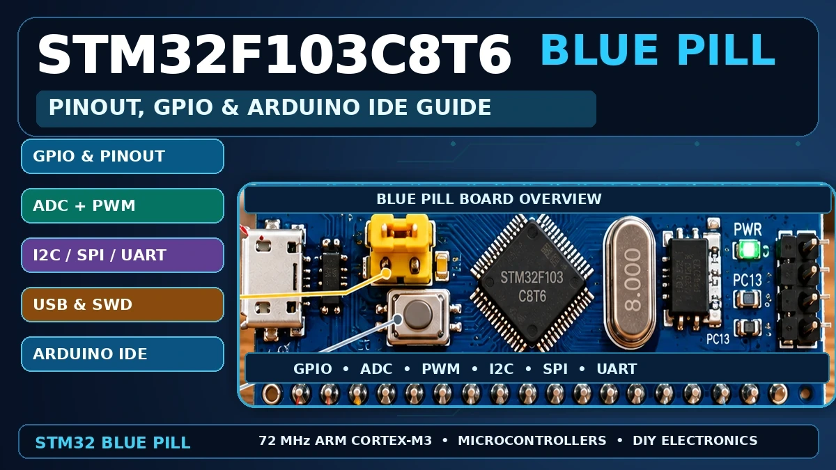
What Is the STM32 Blue Pill?
The Blue Pill is one of the boards that made 32-bit STM32 microcontrollers accessible to Arduino users. It is roughly breadboard-sized, inexpensive and exposes nearly every useful pin of the 48-pin STM32F103 package. Unlike an Arduino Uno, the Blue Pill runs a 32-bit Arm Cortex-M3 core at up to 72 MHz and gives you much more RAM, more timers, multiple serial ports, native USB-device hardware and a CAN peripheral.
Unlike an ESP32 development board, however, the classic Blue Pill has no Wi-Fi, no Bluetooth and no onboard USB-to-serial converter. Its Micro-USB socket connects directly to the STM32 USB pins. That distinction explains many of the programming problems beginners encounter: plugging in a new Blue Pill does not automatically create a serial port or a factory DFU device.
There are many Blue Pill clones and revisions. Header labelling, voltage regulators, USB pull-up resistors and even the fitted microcontroller can vary. This guide is based on the conventional STM32F103C8T6 Blue Pill layout and the current official STM32 Arduino core. Always compare the labels printed on your physical board before connecting power or a programmer.
STM32F103C8T6 Blue Pill Specifications
| Feature | STM32F103C8T6 / typical Blue Pill |
|---|---|
| CPU | Arm Cortex-M3 |
| Maximum clock | 72 MHz |
| Official flash for STM32F103C8 | 64 KB |
| SRAM | 20 KB |
| Core logic | 3.3 V |
| MCU supply range | 2.0–3.6 V |
| ADC | Two 12-bit ADCs; 10 external analogue channels on this board/package |
| USART | 3 |
| I²C | 2 |
| SPI | 2 |
| USB | USB 2.0 full-speed device peripheral |
| CAN | CAN 2.0B controller; external CAN transceiver required |
| Debug | SWD / JTAG |
| Typical HSE crystal | 8 MHz |
| Typical LSE crystal | 32.768 kHz |
| Onboard LED | PC13, active-low |
| Board size | Approximately 23 × 53 mm, depending on clone |
Flash-size warning: the official ST part-number definition matters. STM32F103C8 is a 64 KB flash device; STM32F103CB is the 128 KB version. Some historical Blue Pill tutorials selected a 128 KB option because certain C8-marked devices appeared to have usable flash above 64 KB. That is not something software should assume. Select the C8 target for a genuine C8 unless you have positively identified or tested a different part.
Blue Pill Pinout at a Glance
USB connector
      │
      ▼
┌───────────────────────────────┐
│        STM32F103C8T6          │
│                               │
│ Header 1             Header 2 │
│ VBAT                  3V3     │
│ PC13   LED            GND     │
│ PC14                  5V      │
│ PC15                  PB9     │
│ PA0    A0             PB8     │
│ PA1    A1             PB7 SDA │
│ PA2    A2             PB6 SCL │
│ PA3    A3             PB5     │
│ PA4    A4 / SPI SS    PB4     │
│ PA5    A5 / SPI SCK   PB3     │
│ PA6    A6 / SPI MISO  PA15    │
│ PA7    A7 / SPI MOSI  PA12 USB+│
│ PB0    A8             PA11 USB-│
│ PB1    A9             PA10 RX1│
│ PB10                  PA9  TX1│
│ PB11                  PA8     │
│ NRST                  PB15    │
│ 3V3                   PB14    │
│ GND                   PB13    │
│ GND                   PB12    │
└───────────────────────────────┘

Separate SWD header:
3V3 | SWDIO (PA13) | SWCLK (PA14) | GND

BOOT jumpers:
BOOT0 and BOOT1 (PB2)
The diagram above is intended as a practical orientation guide rather than a substitute for the silkscreen on your board. Clone manufacturers sometimes reverse the physical orientation or change connector details while keeping the same signal names.
Full Blue Pill Header Pinout
| Position | Header 1 | Header 2 |
|---|---|---|
| 1 | VBAT | 3.3 V |
| 2 | PC13 — onboard LED | GND |
| 3 | PC14 — LSE OSC32_IN | 5 V |
| 4 | PC15 — LSE OSC32_OUT | PB9 |
| 5 | PA0 — A0 / ADC | PB8 |
| 6 | PA1 — A1 / ADC | PB7 — default I²C SDA |
| 7 | PA2 — A2 / ADC / USART2 TX | PB6 — default I²C SCL |
| 8 | PA3 — A3 / ADC / USART2 RX | PB5 |
| 9 | PA4 — A4 / ADC / SPI1 SS | PB4 |
| 10 | PA5 — A5 / SPI1 SCK | PB3 |
| 11 | PA6 — A6 / SPI1 MISO | PA15 |
| 12 | PA7 — A7 / SPI1 MOSI | PA12 — USB D+ |
| 13 | PB0 — A8 / ADC | PA11 — USB D− |
| 14 | PB1 — A9 / ADC | PA10 — USART1 RX |
| 15 | PB10 — I²C2 SCL / USART3 TX | PA9 — USART1 TX |
| 16 | PB11 — I²C2 SDA / USART3 RX | PA8 |
| 17 | NRST | PB15 |
| 18 | 3.3 V | PB14 |
| 19 | GND | PB13 |
| 20 | GND | PB12 |
The STM32 pin names are more useful than Arduino-style D numbers because the names directly identify the GPIO port and bit. PA6 means port A, bit 6; PB11 means port B, bit 11. Most STM32 examples, datasheets, schematics and peripheral tables use this notation.
Arduino Pin Numbers vs STM32 Pin Names
The official Arduino STM32 Blue Pill variant also gives the pins sequential Arduino digital numbers. Those numbers are valid, but using PA0, PB7 and similar names usually makes STM32 code clearer and avoids confusion when comparing your sketch with the datasheet.
| Arduino digital alias | STM32 pin | Useful note |
|---|---|---|
| D0 | PB9 | GPIO / alternate peripheral functions |
| D1 | PB8 | GPIO / alternate peripheral functions |
| D2 | PB7 | Default I²C SDA |
| D3 | PB6 | Default I²C SCL |
| D4 | PB5 | GPIO |
| D5 | PB4 | JTAG-related at reset; reusable with correct debug remap |
| D6 | PB3 | JTAG-related at reset; reusable with correct debug remap |
| D7 | PA15 | JTAG-related at reset; reusable with correct debug remap |
| D8 | PA12 | USB D+ |
| D9 | PA11 | USB D− |
| D10 | PA10 | USART1 RX |
| D11 | PA9 | USART1 TX |
| D12 | PA8 | GPIO / timer |
| D17 | PC13 | Onboard LED |
| D20 / A0 | PA0 | ADC input |
| D27 / A7 | PA7 | ADC / SPI1 MOSI |
| D28 / A8 | PB0 | ADC input |
| D29 / A9 | PB1 | ADC input |
| D32 | PB2 | BOOT1 |
| D33 | PA13 | SWDIO |
| D34 | PA14 | SWCLK |
You do not need to memorise these D numbers. For example, pinMode(PA5, OUTPUT); is valid in the official STM32 Arduino core and tells you exactly which physical STM32 pin the sketch is using.
Which Blue Pill GPIOs Are Best to Use?
The STM32F103 does not have the same boot-strapping-pin problem as an ESP32, but several pins are already useful for debugging, boot selection, crystals or fixed board functions. For a first project, it is sensible to leave those special-purpose pins alone until you need them.
| Pin group | Recommendation | Why |
|---|---|---|
| PA0–PA8 | Excellent starting GPIOs | Easy to reach; many ADC/timer/SPI/USART functions |
| PB0, PB1 | Excellent starting GPIOs | Also provide analogue inputs A8/A9 |
| PB5, PB6, PB7, PB10–PB15 | Generally easy to use | Useful GPIO/peripheral pins with no onboard LED/USB connection |
| PC13 | Use with care | Connected to onboard active-low LED; best for low-speed status use |
| PC14, PC15 | Use with care | Connected to the 32.768 kHz LSE crystal on typical Blue Pills |
| PA9, PA10 | Reserve if using serial upload/USART1 | USART1 TX/RX; ROM serial bootloader uses this interface |
| PA11, PA12 | Reserve if using USB | USB D− / D+ |
| PA13, PA14 | Keep for SWD while developing | SWDIO / SWCLK |
| PA15, PB3, PB4 | Use with care | JTAG functions are active after reset unless debug configuration/remap releases them |
| PB2 | Avoid as casual GPIO | BOOT1 selection on the Blue Pill |
Peripheral multiplexing is a strength of STM32, not a reason to fear the pinout. A pin may support GPIO, a timer channel and a serial peripheral, but only the function selected by your firmware is active. The practical rule is to plan the interfaces you need first, then allocate the remaining pins as general GPIO.
3.3 V Logic and 5 V Safety
Treat the Blue Pill as a 3.3 V board. The STM32F103 itself operates from a maximum 3.6 V supply. Many digital I/O pads are 5 V-tolerant when the ST datasheet marks them as FT, but that does not mean every pin can safely accept 5 V in every mode. Analogue inputs, USB pins, oscillator pins and other special pins have different restrictions.
- Do not apply 5 V to an analogue input. Keep ADC signals within the 3.3 V domain unless a properly designed divider or interface is used.
- Do not assume a pin is 5 V-tolerant because a random Blue Pill diagram colours it green. Check the exact STM32 datasheet pin table.
- Use 3.3 V pull-ups for I²C and open-drain signals connected directly to the MCU.
- Level-shift 5 V push-pull sensor outputs when the chosen STM32 pin is not explicitly confirmed as 5 V-tolerant.
- Remember that 5 V-tolerant input does not mean 5 V output. STM32 GPIO outputs remain in the 3.3 V logic domain.
Powering the Blue Pill
A typical Blue Pill can be powered from its Micro-USB connector, the 5 V header rail or the 3.3 V rail. The board normally includes a regulator that generates 3.3 V from the USB/5 V rail.
| Power connection | Use |
|---|---|
| Micro-USB 5 V | Convenient bench power; also connects USB D+/D− to PA12/PA11 |
| 5 V pin | Feeds the board’s 5 V rail/regulator on common Blue Pill designs |
| 3.3 V pin | Direct regulated 3.3 V rail; use only with a clean, correctly regulated source |
| VBAT | Backup-domain supply for RTC/backup registers when VDD is absent |
| GND | Common reference |
Important clone-board warning: the USB 5 V rail and 5 V header are commonly connected directly without ideal-diode isolation. Avoid powering the same board simultaneously from USB and a separate external 5 V supply unless you have checked the schematic of your exact board. Otherwise one supply can back-feed the other.
Onboard LED: PC13 Is Active-Low
The Blue Pill’s user LED is normally connected to PC13 so the STM32 sinks current when the LED is on. That means the logic looks backwards compared with many Arduino boards: LOW turns the LED on and HIGH turns it off.
void setup() {
  pinMode(LED_BUILTIN, OUTPUT);
}

void loop() {
  digitalWrite(LED_BUILTIN, LOW);   // LED ON
  delay(500);

  digitalWrite(LED_BUILTIN, HIGH);  // LED OFF
  delay(500);
}
If a first Blink sketch appears inverted, the board is probably working correctly. This active-low PC13 LED is one of the most recognisable Blue Pill behaviours.
Analogue Inputs: A0 to A9
The STM32F103C8 has 12-bit ADC hardware. On the Blue Pill variant, the Arduino core defines ten convenient external analogue aliases.
| Arduino alias | STM32 pin | ADC use |
|---|---|---|
| A0 | PA0 | ADC input |
| A1 | PA1 | ADC input |
| A2 | PA2 | ADC input |
| A3 | PA3 | ADC input |
| A4 | PA4 | ADC input |
| A5 | PA5 | ADC input |
| A6 | PA6 | ADC input |
| A7 | PA7 | ADC input |
| A8 | PB0 | ADC input |
| A9 | PB1 | ADC input |
void setup() {
  Serial1.begin(115200);
  analogReadResolution(12);
}

void loop() {
  int raw = analogRead(PA0);
  Serial1.println(raw);
  delay(250);
}
With 12-bit resolution, the nominal code range is 0–4095. ADC accuracy depends on supply/reference quality, source impedance, sampling configuration and calibration expectations; do not treat a development board ADC as a precision voltmeter without characterising it. For simple sensors, keep the measured voltage at or below the 3.3 V rail.
I²C Pins
The current official Blue Pill Arduino variant uses PB6 as SCL and PB7 as SDA for the default Wire interface.
| Signal | Default Blue Pill pin |
|---|---|
| I²C SCL | PB6 |
| I²C SDA | PB7 |
#include <Wire.h>

void setup() {
  Wire.begin();
}

void loop() {
}
I²C uses open-drain signalling and requires pull-up resistors. Many breakout boards already include pull-ups. When the sensor is connected directly to the STM32, make sure those pull-ups go to 3.3 V, not 5 V.
SPI Pins
The default SPI interface in the official Blue Pill variant is SPI1 on PA5/PA6/PA7, with PA4 used as the conventional SS pin.
| SPI signal | Default pin |
|---|---|
| SS / NSS | PA4 |
| SCK | PA5 |
| MISO | PA6 |
| MOSI | PA7 |
#include <SPI.h>

void setup() {
  SPI.begin();
  pinMode(PA4, OUTPUT);
  digitalWrite(PA4, HIGH);
}

void loop() {
}
The STM32F103 also has SPI2, so a project is not limited to one hardware SPI peripheral. For ordinary Arduino libraries, the default SPI1 mapping above gives the fewest surprises.
UART / Serial Pins
The STM32F103C8 provides three USART peripherals. The most important one for a Blue Pill beginner is USART1, because it is both the default Arduino serial interface and the interface supported by the STM32F103 medium-density factory system-memory bootloader.
| USART | TX | RX | Typical use |
|---|---|---|---|
| USART1 / Serial1 | PA9 | PA10 | Debug serial or ROM serial bootloader |
| USART2 | PA2 | PA3 | Second hardware serial port |
| USART3 | PB10 | PB11 | Third hardware serial port |
void setup() {
  Serial1.begin(115200);
  Serial1.println("Blue Pill started");
}

void loop() {
}
STM32 Arduino core 3.0.0 note: the core changed the class naming used internally for hardware UART objects. If an old sketch manually declares HardwareSerial and fails after upgrading, check the 3.0.0 migration notes. Code using the predefined Serial1, Serial2 and Serial3 objects is the simplest route for ordinary Blue Pill projects.
USB Pins: PA11 and PA12
| USB signal | STM32 pin |
|---|---|
| USB D− | PA11 |
| USB D+ | PA12 |
The Blue Pill Micro-USB connector is wired directly to these STM32 USB-device pins. With suitable firmware, the board can appear as a USB CDC serial device or another supported USB class.
What it does not give you is a factory USB bootloader on the STM32F103C8. ST’s system-memory bootloader for the medium-density STM32F10xxx family supports USART1, not USB DFU. Therefore a completely blank/new Blue Pill normally needs SWD or USART for its first upload.
Another Blue Pill-specific problem is the USB D+ pull-up resistor. Some clones were built with an incorrect resistor value, which can stop reliable USB enumeration even when the firmware is correct. If SWD programming works but USB does not enumerate, check the USB cable, firmware configuration and the board’s D+ pull-up hardware before assuming the MCU is faulty.
CAN Bus
The STM32F103C8 contains a CAN 2.0B controller, which is one reason the Blue Pill remains useful for automotive and industrial projects. The MCU pins carry logic-level CAN controller signals; they do not connect directly to CANH and CANL.
- Add a suitable 3.3 V-compatible CAN transceiver between the STM32 and the CAN bus.
- The common default CAN mapping uses PA11/PA12, which conflicts with USB.
- A remapped CAN configuration can use PB8/PB9 when the firmware/core configuration supports the remap.
- Use proper CAN termination, wiring and protection for a real vehicle or industrial network.
SWD Programming and Debug Pins
| SWD header | Function |
|---|---|
| 3V3 | Target voltage reference / optional target power depending on programmer setup |
| PA13 | SWDIO |
| PA14 | SWCLK |
| GND | Ground |
SWD is the cleanest way to programme a Blue Pill because it does not depend on a bootloader, USB configuration or user firmware. It also allows debugging. During development, keep PA13 and PA14 reserved for SWD.
The STM32F103 also supports full JTAG. PA15, PB3 and PB4 are associated with JTAG functions after reset on the F1 family. They can be reclaimed as GPIO when the firmware disables/remaps the full JTAG port while retaining SWD, but they are not the pins I would choose for a first project.
BOOT0 and BOOT1: What the Jumpers Do
| BOOT0 | BOOT1 | Boot target | Normal use |
|---|---|---|---|
| 0 | X | User flash | Normal application boot |
| 1 | 0 | System memory | ST factory ROM bootloader; USART1 on STM32F103C8 |
| 1 | 1 | SRAM | Special development/test use |
For day-to-day operation, leave BOOT0 at 0. To use the factory UART bootloader, set BOOT0 to 1 and BOOT1 to 0, reset the board, upload through USART1, then return BOOT0 to 0 and reset again.
Arduino IDE Setup for Blue Pill in 2026
The recommended Arduino route is the official STM32 Arduino core maintained by STMicroelectronics and the STM32duino community. Avoid old tutorials that tell you to install the legacy Roger Clark Maple core as the default solution. The official core supports the STM32F103C6/C8/CB Blue Pill family directly.
Since STM32 Arduino core 2.8.0, the supported development environment is Arduino IDE 2. As of September 2026, the current official STM32 Arduino core release is 3.0.0.
Add the STM32 Boards Manager URL
Open Arduino IDE 2, go to File → Preferences and add this URL to Additional Boards Manager URLs:
https://github.com/stm32duino/BoardManagerFiles/raw/main/package_stmicroelectronics_index.jsonInstall the STM32 Board Package
- Open Tools → Board → Boards Manager.
- Search for STM32 MCU based boards.
- Install the package published for the official STM32 Arduino core.
- Restart the IDE if the new board menus do not appear immediately.
Select the Blue Pill Target
Menu wording can change slightly between core releases, but for a conventional STM32F103C8 Blue Pill choose the Generic STM32F1 series family and the BluePill F103C8 board/part-number option.
Do not select a 128 KB C8 target just because an old blog post says every Blue Pill secretly has 128 KB. The official C8 specification is 64 KB.
Recommended First Upload: ST-Link over SWD
An ST-Link programmer is the method I recommend for the first upload. It is fast, deterministic and gives you a recovery path if USB firmware, boot settings or serial configuration go wrong.
| ST-Link | Blue Pill |
|---|---|
| SWDIO | PA13 / SWDIO |
| SWCLK | PA14 / SWCLK |
| GND | GND |
| 3.3 V / VTref | Connect according to your ST-Link model and chosen target-power arrangement |
- Install STM32CubeProgrammer; the official Arduino STM32 upload methods use it for SWD/serial/DFU workflows where applicable.
- Connect SWDIO, SWCLK and GND.
- Power the target from one controlled source. Avoid connecting two power sources together casually.
- In Arduino IDE, select the Blue Pill target and an STM32CubeProgrammer (SWD)-style upload method.
- Upload the PC13 Blink sketch.
- Leave BOOT0 at 0 for normal flash execution.
If the upload succeeds but the LED does not appear to blink, remember that PC13 is active-low. If the upload fails, first verify common ground, target power, PA13/PA14 wiring and the selected board before changing unrelated Arduino options.
Uploading with a USB-to-Serial Adapter
You can also programme a blank Blue Pill through the STM32 factory system-memory bootloader using a 3.3 V TTL serial adapter. For the STM32F103C8, that bootloader uses USART1.
| USB-TTL adapter | Blue Pill |
|---|---|
| TX | PA10 / USART1 RX |
| RX | PA9 / USART1 TX |
| GND | GND |
| Logic level | 3.3 V logic recommended |
- Set BOOT0 = 1 and BOOT1 = 0.
- Reset or power-cycle the Blue Pill so it enters system memory.
- Choose the appropriate serial STM32CubeProgrammer upload method and COM port in Arduino IDE.
- Upload the sketch.
- Return BOOT0 = 0.
- Reset the board to run your application from flash.
This method requires no custom bootloader. Its disadvantage is the manual BOOT0/reset sequence, which is why SWD is usually more convenient on a development bench.
Can You Upload Directly Through the Blue Pill USB Port?
Yes, but the distinction between USB device support and a factory USB bootloader is essential. The STM32F103C8 hardware can run USB-device firmware, and the Arduino STM32 core supports USB CDC. The core also has support for Maple-style bootloader workflows.
A stock STM32F103C8, however, does not enter a ROM USB DFU bootloader just because BOOT0 is moved. For convenient USB-only application uploads you normally first install a compatible custom bootloader or use an application/upload arrangement designed for USB. That initial installation still needs SWD or USART.
For a first Blue Pill article and for recoverability, I would keep the recommendation simple: own an ST-Link and make SWD your baseline. Add USB bootloading later if the project benefits from it.
Simple GPIO Input and Output Example
const uint32_t buttonPin = PA0;
const uint32_t outputPin = PB5;

void setup() {
  pinMode(buttonPin, INPUT_PULLUP);
  pinMode(outputPin, OUTPUT);
}

void loop() {
  bool pressed = (digitalRead(buttonPin) == LOW);
  digitalWrite(outputPin, pressed ? HIGH : LOW);
}
This is ordinary Arduino-style GPIO code; the important Blue Pill difference is that we use STM32 pin names directly. Internal pull-ups/pull-downs are available for many digital-input use cases, but external resistors are still appropriate when the electrical design requires a defined state independent of firmware.
PWM and Timers
Timers are one of the biggest upgrades compared with an 8-bit Arduino. The STM32F103 family provides advanced and general-purpose timers with multiple capture/compare/PWM channels. Many exposed Blue Pill pins can be mapped to timer channels.
For a basic Arduino sketch, analogWrite() can provide PWM on timer-capable pins supported by the core. For motor control, input capture, precise frequencies, complementary outputs or dead-time generation, work from the STM32 timer/peripheral mapping rather than assuming every GPIO behaves identically.
PA8 is a useful example because it is associated with a TIM1 channel and is easy to access, but your final pin selection should consider all other peripherals in the project.
Blue Pill vs Arduino Uno
| Feature | STM32F103C8 Blue Pill | Arduino Uno R3 |
|---|---|---|
| CPU | 32-bit Arm Cortex-M3 | 8-bit AVR ATmega328P |
| Clock | 72 MHz | 16 MHz |
| Flash | 64 KB official C8 | 32 KB |
| SRAM | 20 KB | 2 KB |
| Logic | 3.3 V | 5 V |
| ADC | 12-bit | 10-bit |
| Hardware USARTs | 3 | 1 |
| Native USB device in MCU | Yes | No on ATmega328P itself |
| CAN controller | Yes, transceiver required | No |
| Wi-Fi / Bluetooth | No | No |
| Debug interface | SWD/JTAG | ISP/debug options differ |
The Blue Pill is considerably more capable computationally, but the Uno remains simpler for 5 V beginner circuits and has a built-in USB programming path on the standard board. The Blue Pill rewards you for learning proper 3.3 V interfacing, SWD and peripheral pin mapping.
Blue Pill vs ESP32
The Blue Pill and ESP32 overlap as low-cost 32-bit development boards, but they target different strengths. The STM32F103 offers deterministic microcontroller peripherals, excellent timers, CAN and mature SWD debugging. An ESP32 adds integrated Wi-Fi/Bluetooth, much more RAM and typically higher processing capability, which makes it the obvious choice for connected Home Assistant and IoT projects.
That difference is useful rather than competitive. An STM32 can handle a real-time control task while an ESP32 provides networking, or either device can be chosen independently when its peripheral set better suits the project.
Common Blue Pill Problems and Fixes
| Problem | Likely cause | What to check |
|---|---|---|
| LED logic appears backwards | PC13 LED is active-low | LOW = on, HIGH = off |
| Board powers from USB but no COM port appears | No onboard USB-UART; USB firmware not running | Use ST-Link/USART first or configure USB CDC firmware |
| BOOT0=1 does not create USB DFU | STM32F103C8 ROM bootloader is USART-based | Use USART1 or SWD |
| Sketch too large / 128 KB confusion | C8 officially has 64 KB flash | Select BluePill F103C8 unless part/flash is verified otherwise |
| USB firmware works on one board but not another | Clone cable/pull-up/hardware differences | Check data cable and USB D+ pull-up implementation |
| ST-Link cannot see target | SWD wiring, power or ground issue | Check PA13, PA14, GND, target voltage and board selection |
| I²C sensor is unstable | Wrong pins or pull-ups | Use PB6/PB7 defaults and 3.3 V pull-ups |
| ADC reads incorrectly or is damaged | Input exceeds analogue range | Keep analogue signal in the 3.3 V domain |
| PA13/PA14 project pins stop debugging | Those pins are SWD | Reserve them while developing |
| PA15/PB3/PB4 behave unexpectedly | JTAG/debug function conflict | Release full JTAG through proper debug/remap configuration |
| Old serial example no longer compiles | Core 3.0.0 serial class changes | Use predefined Serial1/2/3 or update code for current core |
A Sensible First Blue Pill Project Setup
Blue Pill
├─ Power: USB 5 V or one clean external source
├─ Programmer: ST-Link
│  ├─ PA13 SWDIO
│  ├─ PA14 SWCLK
│  └─ GND
├─ Status: PC13 onboard LED
├─ I2C sensor: PB6 SCL + PB7 SDA
├─ SPI device: PA5 SCK + PA6 MISO + PA7 MOSI
├─ Serial debug: PA9 TX + PA10 RX
└─ BOOT0: 0 for normal operation
That layout leaves the USB pins untouched, keeps SWD available for recovery and uses the interface defaults already defined by the official Arduino core. Once that works, move into alternate pin mappings, extra UARTs, timers, CAN or USB-device firmware.
Final Recommendation
The STM32F103C8T6 Blue Pill is still a useful board in 2026 because it gives you a genuine STM32 development environment for very little money. Its strongest features are not novelty: 72 MHz Cortex-M3 performance, multiple hardware serial ports, good timers, 12-bit ADCs, CAN, USB-device hardware and proper SWD debugging remain valuable for embedded control projects.
The main traps are equally well understood. Treat the board as 3.3 V, remember that the genuine C8 has 64 KB flash, keep PA13/PA14 available for SWD, understand that PC13’s LED is active-low and do not expect the Micro-USB socket to behave like an onboard USB programmer on a fresh board.
For Arduino development, install the current official STM32 core in Arduino IDE 2, select the BluePill F103C8 target and make ST-Link/SWD your recovery path. Once that foundation is in place, the Blue Pill is far less mysterious than its collection of old and contradictory tutorials suggests.
Related ESP32 Guides
- ESP32 DevKitC V4 Pinout Diagram & Safe GPIOs
- ESP32-S3 DevKitC-1 Pinout Diagram & Safe GPIOs
- ESP32 DevKitC V4 Complete Guide: Board, Boot & GPIO Matrix
Datasheets & External Resources
All manufacturer and framework references are collected here so the main article remains focused on esp32.co.uk.
- STMicroelectronics STM32F103C8 Product Page — official device specifications and documentation.
- ST STM32F103x8/xB Datasheet (DS5319) — flash/RAM, electrical limits, I/O characteristics and peripheral specifications.
- ST AN2606 System-Memory Bootloader Application Note — supported factory bootloader interfaces for STM32 families, including STM32F10xxx medium-density devices.
- Official Arduino Core for STM32 — current supported boards, source code and package information.
- STM32duino Getting Started — Arduino IDE 2 and Boards Manager setup.
- STM32duino Upload Methods — SWD, serial, DFU and STM32CubeProgrammer workflows.
- Arduino Core for STM32 3.0.0 — current 2026 major release and migration changes.
- STM32CubeProgrammer — ST programming utility used by official STM32 upload workflows.
- STM32-base Blue Pill Hardware Reference — conventional board header layout, crystals, power rails and common USB pull-up issue.