Quick Summary (TL;DR):
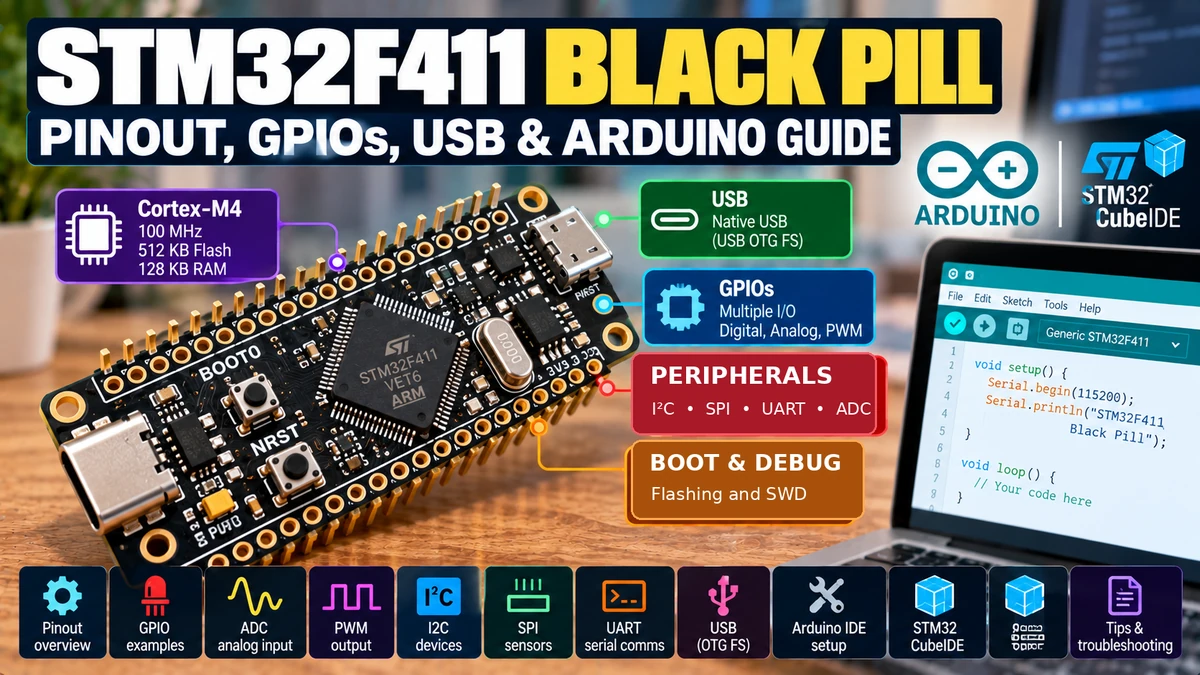
The STM32F411CEU6 Black PillAliExpress price is a compact STM32 development board built around a 100 MHz Arm Cortex-M4 with single-precision FPU and DSP instructions. The F411CE provides 512 KB flash and 128 KB SRAM, a 12-bit ADC, hardware timers, three I²C controllers, three USARTs, multiple SPI/I²S interfaces, SDIO and USB 2.0 full-speed OTG. The common WeAct Black PillAliExpress price uses a USB-C connector, an active-low PC13 user LED, a PA0 user button, BOOT0 and reset buttons, plus a 4-pin SWD header. In the official STM32 Arduino core, default I²C is PB6/PB7, default SPI is PA5/PA6/PA7 with PA4 as SS, and the default UART is PA9/PA10. USB uses PA11/PA12. Unlike the older STM32F103 Blue Pill, the STM32F411AliExpress price system-memory bootloader supports USB DFU, so a stock Black PillAliExpress price can be flashed over USB without first installing a custom bootloader. For debugging and recovery, SWD with an ST-Link remains the best development setup. Use Arduino IDE 2 with the official STM32 MCU based boards package and select the BlackPill F411CE target.
What Is the STM32F411 Black Pill?
The Black PillAliExpress price is the natural step up from the classic STM32F103 Blue Pill. It keeps the same idea — a small, breadboard-friendly board that exposes a large number of MCU pins — but moves to the STM32F4 family and a much more capable Cortex-M4 processor.
The version covered here is the STM32F411CEU6 WeAct-style Black Pill, commonly sold as the Black Pill F411CE. It should not be confused with older Black Pill boards built around STM32F401 devices. The board layouts are similar, but the F411CE runs at up to 100 MHz and has 128 KB SRAM.
The Black Pill is particularly attractive for USB devices, HID controllers, audio experiments, robotics, instrumentation, data acquisition, motion control and embedded projects that need more CPU performance than the F103 but do not require built-in Wi-Fi or Bluetooth.
STM32F411CEU6 Specifications
| Feature | STM32F411CEU6 |
|---|---|
| CPU | Arm Cortex-M4 with DSP instructions and single-precision FPU |
| Maximum CPU clock | 100 MHz |
| Flash | 512 KB |
| SRAM | 128 KB |
| MCU operating supply | 1.7–3.6 V |
| Board logic | 3.3 V |
| ADC | 1 × 12-bit ADC, up to 2.4 MSPS |
| Timers | Up to 11 timers including 16-bit and 32-bit timers |
| I²C | Up to 3 |
| USART | Up to 3 |
| SPI / I²S | Multiple hardware interfaces |
| SDIO | Yes |
| USB | USB 2.0 full-speed device/host/OTG with on-chip PHY |
| Factory USB bootloader | Yes — USB DFU in system memory |
| Debug | SWD / JTAG |
| Common WeAct HSE | 25 MHz on many boards; 8 MHz variants also exist |
| Common LSE | 32.768 kHz |
| User LED | PC13, active-low |
| User button | PA0, active-low on common WeAct boards |
A useful practical detail is that Black Pill hardware revisions exist. WeAct has sold versions using both 25 MHz and 8 MHz HSE crystals. The official STM32 Arduino variant includes support for both. Check the marking on the crystal or the exact board listing if clock-sensitive firmware behaves unexpectedly.
Black Pill Pinout at a Glance
USB-C connector
        │
        ▼
┌──────────────────────────────────┐
│       STM32F411CEU6 Black Pill   │
│                                  │
│ Header 1               Header 2  │
│ 5V                     PB12      │
│ GND                    PB13      │
│ 3V3                    PB14      │
│ PB10                   PB15      │
│ PB2                    PA8       │
│ PB1 / A9               PA9 TX1   │
│ PB0 / A8               PA10 RX1  │
│ PA7 / A7 MOSI          PA11 USB- │
│ PA6 / A6 MISO          PA12 USB+ │
│ PA5 / A5 SCK           PA15      │
│ PA4 / A4 SS            PB3       │
│ PA3 / A3 RX2           PB4       │
│ PA2 / A2 TX2           PB5       │
│ PA1 / A1               PB6 SCL   │
│ PA0 / A0 / USER KEY    PB7 SDA   │
│ NRST                   PB8       │
│ PC15                   PB9       │
│ PC14                   5V        │
│ PC13 / USER LED        GND       │
│ VBAT                   3V3       │
└──────────────────────────────────┘

Separate SWD header:
3V3 | SWDIO (PA13) | SWCLK (PA14) | GND

Onboard buttons:
BOOT0 | NRST | USER (PA0, on common v3.1 boards)
This arrangement matches the common WeAct-style board layout. Clone boards may move labels, use a different regulator or omit the user button or optional flash footprint, so the silkscreen on the physical board remains the final reference.
Full Black Pill Header Pinout
| Header 1 pin | Signal | Header 2 pin | Signal |
|---|---|---|---|
| 1 | 5 V | 1 | PB12 |
| 2 | GND | 2 | PB13 |
| 3 | 3.3 V | 3 | PB14 |
| 4 | PB10 | 4 | PB15 |
| 5 | PB2 | 5 | PA8 |
| 6 | PB1 / A9 | 6 | PA9 / USART1 TX |
| 7 | PB0 / A8 | 7 | PA10 / USART1 RX |
| 8 | PA7 / A7 / SPI1 MOSI | 8 | PA11 / USB D− |
| 9 | PA6 / A6 / SPI1 MISO | 9 | PA12 / USB D+ |
| 10 | PA5 / A5 / SPI1 SCK | 10 | PA15 |
| 11 | PA4 / A4 / SPI1 SS | 11 | PB3 |
| 12 | PA3 / A3 / USART2 RX | 12 | PB4 |
| 13 | PA2 / A2 / USART2 TX | 13 | PB5 |
| 14 | PA1 / A1 | 14 | PB6 / default I²C SCL |
| 15 | PA0 / A0 / USER | 15 | PB7 / default I²C SDA |
| 16 | NRST | 16 | PB8 |
| 17 | PC15 | 17 | PB9 |
| 18 | PC14 | 18 | 5 V |
| 19 | PC13 / onboard LED | 19 | GND |
| 20 | VBAT | 20 | 3.3 V |
Arduino Pin Names and Analogue Aliases
As with the Blue Pill, the cleanest way to write Arduino code for STM32 is to use the native STM32 pin names. A statement such as pinMode(PB5, OUTPUT); is easier to compare with the datasheet and schematic than a board-specific D-number.
The current official BlackPill F411CE Arduino variant defines 36 digital pins and 10 analogue inputs. The analogue aliases are PA0–PA7 plus PB0 and PB1.
| Analogue alias | STM32 pin | Typical use |
|---|---|---|
| A0 | PA0 | ADC / onboard user button |
| A1 | PA1 | ADC |
| A2 | PA2 | ADC / USART2 TX |
| A3 | PA3 | ADC / USART2 RX |
| A4 | PA4 | ADC / SPI1 SS |
| A5 | PA5 | ADC / SPI1 SCK |
| A6 | PA6 | ADC / SPI1 MISO |
| A7 | PA7 | ADC / SPI1 MOSI |
| A8 | PB0 | ADC |
| A9 | PB1 | ADC |
Best GPIO Pins to Use
The Black Pill exposes a very flexible pin set, but several pins have board-level or development functions worth reserving. There are fewer boot-related GPIO complications than on ESP32, yet USB, SWD, crystals and onboard controls still matter.
| Pins | Recommendation | Reason |
|---|---|---|
| PA1–PA8 | Excellent general-purpose choices | Accessible GPIO with ADC/timer/peripheral options |
| PB0, PB1, PB2, PB5–PB10, PB12–PB15 | Generally good GPIO choices | Useful exposed pins with many alternate functions |
| PA0 | Use with care | Connected to the onboard USER button on common WeAct boards |
| PC13 | Use with care | Connected to the onboard active-low LED |
| PC14, PC15 | Reserve if using LSE | Typically connected to the 32.768 kHz crystal |
| PA9, PA10 | Reserve if using default serial | USART1 TX/RX |
| PA11, PA12 | Reserve for USB | USB D− / D+ |
| PA13, PA14 | Keep for SWD while developing | SWDIO / SWCLK on separate debug header |
| PA15, PB3, PB4 | Check debug/peripheral use | Can participate in JTAG/alternate peripheral functions |
3.3 V Logic and 5 V Tolerance
The Black Pill is a 3.3 V logic board. The STM32F411 operates from a low-voltage supply even though many of its digital I/O pads are specified as 5 V-tolerant.
- Do not interpret 5 V tolerance as permission to apply 5 V to every pin.
- Analogue inputs should remain inside the valid ADC voltage range; use a divider or level interface for higher-voltage signals.
- USB, oscillator, power and other special-function pins have their own electrical restrictions.
- Use 3.3 V pull-ups for I²C devices connected directly to the MCU.
- STM32 GPIO outputs remain approximately 3.3 V logic even when a digital input is 5 V-tolerant.
- For an important or expensive design, verify the exact pin’s FT designation and conditions in the STM32F411 datasheet.
Powering the Black Pill Safely
| Connection | Purpose |
|---|---|
| USB-C | Provides 5 V board power and USB D+/D− connection |
| 5 V pin | Feeds the board’s 5 V rail/regulator |
| 3.3 V pin | Direct regulated 3.3 V rail |
| VBAT | Backup-domain supply for RTC/backup registers |
| GND | Common reference |
On common WeAct Black Pill designs, the USB 5 V rail and the header 5 V rail are directly connected without power-source isolation. Do not casually power the board from USB and an external 5 V source at the same time. If your application can be connected to two supplies, design the power path deliberately.
Onboard LED: PC13
The user LED is connected to PC13 and is normally active-low. LOW sinks current and turns the LED on; HIGH turns it off.
void setup() {
  pinMode(LED_BUILTIN, OUTPUT);
}

void loop() {
  digitalWrite(LED_BUILTIN, LOW);   // LED ON
  delay(500);

  digitalWrite(LED_BUILTIN, HIGH);  // LED OFF
  delay(500);
}
Onboard User Button: PA0
Common WeAct Black Pill v3.x boards include a user button connected to PA0. The official STM32 Arduino variant also defines the user-button pin as PA0.
void setup() {
  pinMode(PA0, INPUT_PULLUP);
  pinMode(LED_BUILTIN, OUTPUT);
}

void loop() {
  bool pressed = (digitalRead(PA0) == LOW);
  digitalWrite(LED_BUILTIN, pressed ? LOW : HIGH);
}
Older board revisions may not have the separate user key, so check the board itself before relying on this feature.
ADC: 12-Bit Analogue Inputs
The STM32F411 contains one 12-bit ADC capable of up to 2.4 MSPS at the MCU level. The Black Pill exposes ten convenient external ADC pins through PA0–PA7, PB0 and PB1.
void setup() {
  Serial.begin(115200);
  analogReadResolution(12);
}

void loop() {
  uint16_t raw = analogRead(PA1);
  Serial.println(raw);
  delay(200);
}
A 12-bit conversion gives a nominal 0–4095 code range. Real accuracy depends on supply noise, source impedance, ADC sampling time and layout. For precision measurements, follow ST’s ADC accuracy guidance rather than relying only on the nominal resolution.
I²C Pins
The official Arduino BlackPill F411CE variant sets the default Wire interface to PB6 for SCL and PB7 for SDA.
| I²C signal | Default pin |
|---|---|
| SCL | PB6 |
| SDA | PB7 |
#include <Wire.h>

void setup() {
  Wire.begin();
}

void loop() {
}
The STM32F411 itself supports up to three I²C controllers, so advanced designs can use additional hardware buses. For ordinary Arduino sensor libraries, PB6/PB7 is the least surprising default.
SPI Pins
Default Arduino SPI uses the familiar SPI1 mapping on PA4–PA7.
| SPI signal | Default pin |
|---|---|
| SS / NSS | PA4 |
| SCK | PA5 |
| MISO | PA6 |
| MOSI | PA7 |
#include <SPI.h>

void setup() {
  SPI.begin();
  pinMode(PA4, OUTPUT);
  digitalWrite(PA4, HIGH);
}

void loop() {
}
Some Black Pill versions include or provide a footprint for external SPI flash. On those variants, PA4/PA5/PA7 and another data pin can already be associated with the onboard flash footprint. Confirm whether your particular board actually has a flash chip fitted before allocating those pins.
UART / Serial Pins
The official Arduino board variant uses USART1 on PA9/PA10 as the default hardware serial mapping.
| Interface | TX | RX | Typical use |
|---|---|---|---|
| USART1 | PA9 | PA10 | Default hardware serial / bootloader option |
| USART2 | PA2 | PA3 | Second hardware serial |
| USART6 | PA11 | PA12 | Alternate serial function, but conflicts with USB |
If you use the USB connector as a virtual COM port, you can often leave PA9/PA10 free for a sensor, GPS, motor controller or other UART peripheral.
USB-C: PA11 and PA12
| USB signal | STM32 pin |
|---|---|
| USB D− | PA11 |
| USB D+ | PA12 |
| USB VBUS | 5 V board rail / USB connector |
USB is one of the Black Pill’s strongest features. The STM32F411 contains a USB 2.0 full-speed device/host/OTG controller with an on-chip PHY. The WeAct board routes PA11 and PA12 directly to its USB-C connector.
This makes the board suitable for USB CDC serial devices, HID keyboards/controllers, MIDI, custom USB devices and other supported classes. Host/OTG functionality requires more attention to power and connector behaviour than simple USB-device mode.
Factory USB DFU Bootloader
This is a major difference between the Black Pill F411 and the Blue Pill F103. The STM32F411 factory system-memory bootloader supports USB DFU. You do not have to install a third-party USB bootloader before the board can be programmed through USB.
Entering DFU Mode
- Connect the Black Pill to the computer with a data-capable USB-C cable.
- Hold the BOOT0 button.
- Press and release NRST while BOOT0 remains asserted, or hold BOOT0 while powering/resetting the board.
- Release BOOT0 after the MCU has entered system-memory boot mode.
- The device should enumerate as an STM32 DFU device.
- Use STM32CubeProgrammer or the Arduino STM32 DFU upload method to flash the firmware.
- Press NRST again normally to boot the new application from flash.
DFU mode runs from the immutable ST bootloader stored in system memory, so it remains an excellent recovery method even when the application in flash is broken.
SWD Programming and Debugging
USB DFU is convenient, but SWD is still the best serious development interface. It gives you direct programming, debugging and a robust recovery path.
| SWD header | Connection |
|---|---|
| 3.3 V | Target voltage reference / power only when appropriate for your programmer setup |
| SWDIO | PA13 |
| SWCLK | PA14 |
| GND | GND |
Keep PA13 and PA14 dedicated to SWD while developing. They are available as MCU pins, but reusing them as project GPIOs removes the easiest debug connection.
BOOT0 and Boot Behaviour
The Black Pill includes a BOOT0 push button instead of requiring the jumper arrangement familiar from many Blue Pill boards. Holding BOOT0 during reset selects the STM32 system-memory bootloader, which can communicate through supported interfaces including USB DFU.
| BOOT0 during reset | Result |
|---|---|
| Low / not pressed | Normal boot from user flash |
| High / held | System-memory bootloader — enables DFU and other supported boot interfaces |
For normal Arduino operation you simply leave BOOT0 alone. Use it only when you intentionally want the ROM bootloader, such as for a DFU upload or recovery.
Arduino IDE Setup in 2026
Use Arduino IDE 2 with the official STM32 Arduino core maintained by STMicroelectronics and the STM32duino community. The BlackPill F411CE is an explicitly supported board target.
Add the STM32 Boards Manager URL
In Arduino IDE open File → Preferences and add this to Additional Boards Manager URLs:
https://github.com/stm32duino/BoardManagerFiles/raw/main/package_stmicroelectronics_index.jsonInstall the Board Package
- Open Tools → Board → Boards Manager.
- Search for STM32 MCU based boards.
- Install the official STM32 package.
- Select the Generic STM32F4 series family.
- Choose the BlackPill F411CE board/part-number option.
If the menu offers crystal variants, select the one matching the oscillator fitted to your board. Many WeAct Black Pills use 25 MHz HSE, but 8 MHz variants also exist.
Uploading from Arduino IDE with USB DFU
- Select the correct BlackPill F411CE target.
- Select a STM32CubeProgrammer (DFU)-style upload method.
- Enter DFU mode with BOOT0 + reset.
- Confirm that the board appears as an STM32 DFU device.
- Click Upload.
- After programming, reset the board normally so it boots from flash.
Install STM32CubeProgrammer if required by the upload workflow. The Arduino STM32 package relies on ST’s programmer tooling for several upload methods.
USB CDC Serial in Your Sketch
DFU is only for programming. Your application can independently configure the USB peripheral as a CDC virtual serial port. When USB CDC is enabled in the selected Arduino board options, the USB-C connector can provide Serial Monitor communication without using PA9/PA10.
void setup() {
  Serial.begin(115200);

  while (!Serial && millis() < 3000) {
    // Wait briefly for USB CDC host connection
  }

  Serial.println("STM32F411 Black Pill USB serial ready");
}

void loop() {
  Serial.println(millis());
  delay(1000);
}
Exact USB menu options can change between STM32 Arduino core releases, so use the current board menu labels rather than copying an old screenshot. The important hardware fact remains PA11 = D− and PA12 = D+.
Simple GPIO Example
const uint32_t inputPin = PB8;
const uint32_t outputPin = PB5;

void setup() {
  pinMode(inputPin, INPUT_PULLUP);
  pinMode(outputPin, OUTPUT);
}

void loop() {
  digitalWrite(outputPin, digitalRead(inputPin) == LOW ? HIGH : LOW);
}
Native STM32 pin names make code portable between Arduino sketches, CubeMX documentation and the datasheet. They also make wiring mistakes easier to diagnose.
PWM, Timers and Motor Control
The Cortex-M4 CPU is only part of the Black Pill’s appeal. STM32F411 also offers a strong timer subsystem with multiple 16-bit and 32-bit timers, input capture, output compare, PWM and encoder-related capabilities.
Arduino’s analogWrite() is enough for simple PWM output. For precision timing, high-frequency PWM, quadrature encoders, pulse measurement or multi-channel motor control, use the MCU’s timer mappings and the STM32 core APIs rather than treating every pin as an interchangeable Arduino PWM pin.
SDIO and High-Speed Storage
Unlike the STM32F103 Blue Pill, the STM32F411 adds an SDIO peripheral. That can provide a much better path to SD cards than bit-banged or ordinary SPI access when the board pin allocation and software stack support it.
This is useful for data loggers, audio recorders and applications that need sustained storage throughput. The Black Pill does not include an SD socket, so you still need an external socket/module and correct 3.3 V wiring.
Does STM32F411 Have CAN Bus?
No. This is an important point when comparing STM32 boards. The STM32F411 does not provide the classic bxCAN peripheral found on parts such as the STM32F103. If your project specifically requires native CAN, choose a different STM32 family/member or add an external CAN controller over SPI.
This is one reason the F411 Black Pill is not a universal replacement for the F103 Blue Pill: it is much faster and better for USB, but peripheral requirements still decide which MCU is the better fit.
Black Pill vs Blue Pill
| Feature | STM32F411 Black Pill | STM32F103C8 Blue Pill |
|---|---|---|
| Core | Cortex-M4 + FPU/DSP | Cortex-M3 |
| Max clock | 100 MHz | 72 MHz |
| Flash | 512 KB | 64 KB official C8 |
| SRAM | 128 KB | 20 KB |
| ADC | 1 × 12-bit | 2 × 12-bit |
| USB hardware | USB FS OTG | USB FS device |
| Factory USB DFU | Yes | No |
| CAN controller | No | Yes |
| SDIO | Yes | No |
| FPU | Yes | No |
| Common USB connector | USB-C on WeAct board | Micro-USB on common Blue Pill |
| SWD | Yes | Yes |
For a general-purpose Arduino-style STM32 board, the F411 Black Pill is substantially more powerful. The F103 Blue Pill remains interesting when native CAN or its specific F1 peripheral set matters.
Black Pill vs ESP32
| Feature | STM32F411 Black Pill | Typical ESP32 development board |
|---|---|---|
| CPU focus | Deterministic MCU control, Cortex-M4 + FPU | Higher integration and wireless SoC |
| Wi-Fi | No | Yes |
| Bluetooth | No | Yes on many ESP32 variants |
| USB | Native USB OTG FS | Depends on ESP32 variant |
| Debug | SWD | JTAG/USB-JTAG depending on variant |
| Home Assistant / ESPHome | Not the natural target | Excellent |
| Real-time control | Excellent | Excellent, but wireless stack may influence design |
| FPU/DSP | Cortex-M4 DSP/FPU | Architecture dependent |
If the project needs Wi-Fi, Bluetooth, MQTT or ESPHome, an ESP32 is usually the easier choice. If the project needs USB device behaviour, precise timers, SWD debugging and a conventional STM32 toolchain, the Black Pill is extremely attractive.
Common Black Pill Problems
| Problem | Likely cause | What to check |
|---|---|---|
| USB powers board but DFU does not appear | Wrong boot sequence or charge-only cable | Use a data cable; hold BOOT0 during reset |
| Arduino upload cannot find DFU target | Board is running user flash instead of system bootloader | Re-enter BOOT0 + NRST sequence |
| Sketch runs at wrong timing | Incorrect HSE selection | Check whether board has 25 MHz or 8 MHz crystal |
| LED behaviour seems inverted | PC13 LED is active-low | LOW = on, HIGH = off |
| User button example does nothing | Older board revision lacks user key | Check physical board revision |
| I²C device not detected | Wrong pins/pull-ups | Use default PB6/PB7 and 3.3 V pull-ups |
| SPI flash conflicts with external device | Onboard/optional flash shares pins | Check whether flash is fitted and which board revision you own |
| USB CDC disappears after changing sketch | Application USB configuration changed | DFU recovery remains available through system memory |
| ST-Link cannot connect | SWD wiring/power issue | Check PA13, PA14, GND and target voltage |
| External 5 V supply gets hot / USB conflict | Two power sources tied together | Use one supply or design proper isolation |
| CAN library does not work | STM32F411 has no bxCAN peripheral | Use external CAN controller or different STM32 |
Recommended Development Setup
STM32F411 Black Pill
├─ Power: USB-C OR one external supply
├─ USB programming: factory DFU
│  ├─ BOOT0
│  └─ NRST
├─ Debug/recovery: ST-Link SWD
│  ├─ PA13 SWDIO
│  ├─ PA14 SWCLK
│  └─ GND
├─ Status LED: PC13
├─ User button: PA0
├─ I2C: PB6 SCL + PB7 SDA
├─ SPI1: PA5 SCK + PA6 MISO + PA7 MOSI
├─ Serial1: PA9 TX + PA10 RX
└─ USB: PA11 D- + PA12 D+
This setup preserves SWD, keeps USB available and follows the default Arduino peripheral mappings. It is a good baseline before experimenting with alternate-function remapping or advanced STM32 HAL features.
Which Black Pill Version Should You Buy?
For this class of board, the STM32F411CE version is the one I would choose over the older F401 variants unless price or an existing design dictates otherwise. It provides 100 MHz operation, 512 KB flash and 128 KB SRAM in a very compact board.
The bigger purchasing concern is authenticity and board revision. Buy from a source that clearly identifies the MCU, oscillator frequency and board revision. Some boards have optional external SPI flash fitted while others only provide the footprint.
Do not assume every black PCB called a ‘Black Pill’ is electrically identical. Check the actual part marking STM32F411CEU6 if that is the device your project requires.
Final Recommendation
The STM32F411 Black Pill is one of the best low-cost ways to move from Arduino-style development into a much more capable STM32 environment. The 100 MHz Cortex-M4 core, FPU, 512 KB flash, 128 KB SRAM, native USB OTG, good timer resources and SWD debugging provide a lot of capability in a board barely larger than a Blue Pill.
Its most convenient feature for beginners is the factory USB DFU bootloader. With BOOT0 and reset, you can recover and reflash a stock board over USB-C without installing a third-party bootloader first. For serious development, add an ST-Link so you also have SWD debugging.
The main cautions are straightforward: use 3.3 V logic, preserve PA11/PA12 if you need USB, keep PA13/PA14 available for SWD, verify the oscillator fitted to your board and remember that the F411 does not have the native CAN peripheral found on the F103.
Related Guides
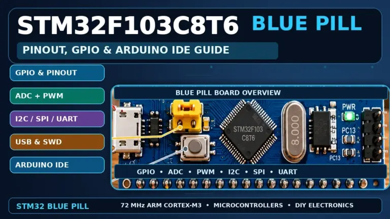
- STM32F103C8T6 Blue Pill Pinout, GPIOs & Arduino IDE Guide
- ESP32 DevKitC V4 Pinout Diagram & Safe GPIOs
- ESP32-S3 DevKitC-1 Pinout Diagram & Safe GPIOs
Datasheets & External Resources
Manufacturer, framework and board references are collected here for pin mapping, electrical limits and upload details.
- STMicroelectronics STM32F411CE Product Page — official CPU, memory, ADC, timer, USB and interface specifications.
- STM32F411 Documentation — DS10314 datasheet, RM0383 reference manual, errata and programming documents.
- ST AN2606 System-Memory Bootloader Application Note — confirms USB DFU, USART, SPI and I²C boot interfaces for STM32F411.
- Official Arduino Core for STM32 — current STM32 Arduino support.
- Official BlackPill F411CE Arduino Variant — default SPI, I²C, UART, LED and user-button definitions.
- WeAct MiniSTM32F4x1 Repository — Black Pill hardware documentation and board revisions.
- STM32-base WeAct Black Pill Hardware Reference — header layout, USB-C, SWD, power rails and board-level details.
- STM32CubeProgrammer — official ST programming utility for DFU, SWD and other boot interfaces.