Quick Summary (TL;DR):
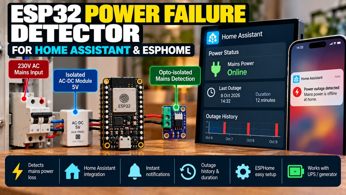
A reliable ESP32AliExpress price power failure detector for Home Assistant needs two independent paths: the ESP32AliExpress price stays alive from a UPS or battery-backed 5 V supply, while a separate isolated signal tells it whether the monitored mains circuit is present. The easiest safe DIY method is an approved USB wall adapter plugged into the circuit you want to monitor. Its low-voltage output drives an optocouplerAliExpress price, dry-contact relay or correctly designed 5 V-to-3.3 V interface; the ESP32AliExpress price itself remains on backup power. Do not connect 230 V directly to an ESP32AliExpress price GPIO or breadboard. In ESPHome, the sense signal becomes a GPIO binary sensor with a short delayed_on_off filter. If the sense signal disappears while the ESP32 remains online, Home Assistant can distinguish a real outage from Wi-Fi loss, a reboot or an ESPHome crash. For immediate notifications during a whole-house outage, the router/access point and Home Assistant host must also stay powered. One ESP32 can also monitor separate circuits such as freezer, boiler, garage or pump supplies, record outage duration and confirm that the detector itself survived the outage.
Materials You’ll Need
| Item | Purpose |
|---|---|
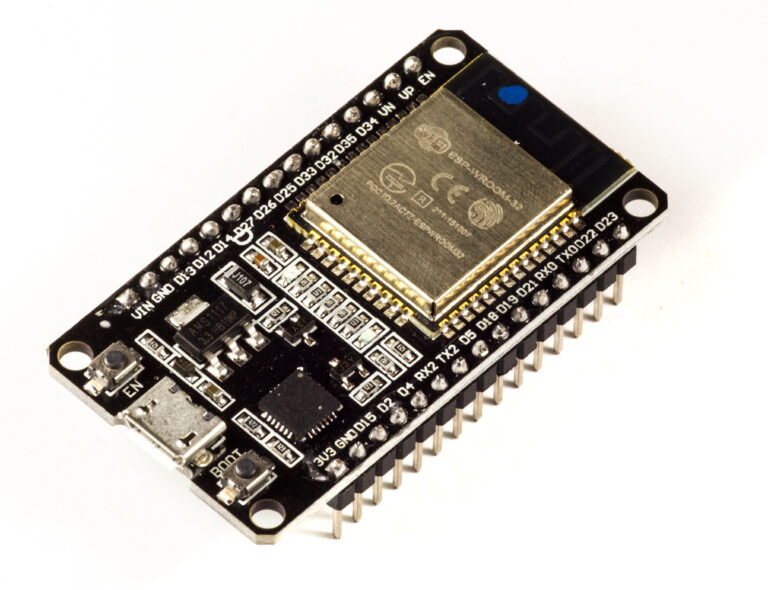
| ESP32 development board | Runs ESPHome and reports the mains state |
| UPS-backed 5 V supply | Keeps the ESP32 alive during the outage |
| Approved isolated USB adapter | Creates a safe low-voltage mains-present signal |
| Optocoupler / dry-contact relay | Interfaces that signal to an ESP32-safe GPIO |
| UPS-backed router/AP | Keeps the local network alive |
| UPS-backed Home Assistant host | Receives, records and acts on the event |
| Optional extra sensing adapters | Monitor individual circuits |
The Architecture That Actually Works
Monitored mains circuit
      ↓
approved 5V adapter
      ↓
optocoupler / dry contact
      ↓
ESP32 GPIO

UPS / battery backup
      ↓
ESP32 power

UPS-backed router + Home Assistant
      ↓
notification + history
The detector must survive the outage. If the ESP32 is powered from the same outlet it monitors, Home Assistant only sees the node disappear and cannot prove why.
Why ‘ESP32 Offline’ Is Not a Good Power-Cut Detector
- mains power failure
- ESP32 reboot
- Wi-Fi access-point failure
- router failure
- Home Assistant API disconnect
- ESPHome crash
- bad USB cable or PSU
- OTA update
A dedicated mains-sense input tells you specifically that the monitored supply disappeared while the monitoring node remained alive.
The Three Failure Domains
| Domain | What can fail | What you need |
|---|---|---|
| Mains sense | Monitored circuit loses power | Independent isolated sense signal |
| ESP32 power | Detector itself loses power | UPS/battery-backed supply |
| Network / Home Assistant | Event cannot reach HA | UPS-backed router/AP + HA host |
Safest DIY Method: Isolated USB Adapter
A small approved USB charger already performs the dangerous mains-to-low-voltage isolation. Plug it into the circuit you want to supervise and use only its low-voltage output as the mains-present signal. This keeps mains wiring out of the ESP32 enclosure.
230V monitored outlet
→ approved USB adapter
→ 5V DC
→ optocoupler / dry contact
→ ESP32-safe GPIO
Option A: USB Adapter + Optocoupler
MONITORED SIDE
5V adapter + → resistor → optocoupler LED → adapter GND

ESP32 SIDE
3.3V → pull-up → GPIO → optocoupler transistor → ESP32 GND
When mains is present, the optocoupler changes the GPIO state. When mains disappears, the transistor releases. This creates a very clean logical separation between the sensing supply and ESP32 side.
Option B: USB Adapter + Small Relay
A small 5 V relay coil powered by the monitored adapter is even easier to understand. Its dry contact connects the ESP32 GPIO to ground. The trade-offs are mechanical noise, slower release and contact wear, though outage sensing changes state so rarely that wear is usually irrelevant.
Option C: USB Adapter + Divider
Because the USB adapter has already isolated the low-voltage output from mains, you can reduce its 5 V output to a safe ESP32 logic level with a resistor divider if the grounds are intentionally shared. An optocoupler or dry contact is usually cleaner when you want the sensing adapter and ESP32 power supplies to remain independent.
5V sense output
   │
  10kΩ
   │
   ├──── ESP32 GPIO (~3.3V)
   │
  20kΩ
   │
  GND
Do Not Connect 230 V Directly to ESP32
Do not build a mains resistor divider into an ESP32 GPIO and do not use a random non-isolated AC detector board unless you understand its isolation, creepage, clearance, enclosure and protection requirements. For a domestic DIY Home Assistant project, an approved plug-in low-voltage adapter is much easier to reason about safely.
Power the ESP32 Independently
- UPS-backed USB output
- small DC UPS module
- battery-backed 5 V board
- another genuinely independent supply when monitoring only one local circuit
For whole-house outage detection, another normal mains circuit is not enough. Use actual battery or UPS backup.
Basic ESPHome GPIO Input
binary_sensor:
  - platform: gpio
    id: mains_present
    name: "Mains Power Present"
    device_class: power
    pin:
      number: GPIO25
      mode:
        input: true
        pullup: true
      inverted: true
    filters:
      - delayed_on_off: 1s
The exact inversion depends on the optocoupler or relay wiring. Verify the physical state: the entity must read ON when mains is actually present.
Why delayed_on_off Helps
ESPHome binary sensors support delayed_on, delayed_off and delayed_on_off filters. A short local delay rejects relay bounce, adapter discharge noise and very brief power flicker. One second is a sensible starting point for general outage monitoring.
Power dip < 1s
→ ignored

Power absent > 1s
→ Mains Power Present = OFF
Create a Power Failure Entity
binary_sensor:
  - platform: template
    id: power_failure
    name: "Power Failure"
    device_class: problem
    lambda: |-
      return !id(mains_present).state;
Keep both Mains Power Present and Power Failure. The raw state is useful for diagnostics; the inverted problem entity is cleaner for alerts.
Home Assistant Power-Lost Notification
alias: Mains power failure
triggers:
  - trigger: state
    entity_id: binary_sensor.mains_power_present
    to: "off"
    for: "00:00:02"
actions:
  - action: notify.mobile_app_phone
    data:
      title: "Power Failure"
      message: "Mains power has been lost."
Home Assistant state triggers can require the new state to remain stable for a chosen period before the automation fires.
Power-Restored Notification
alias: Mains power restored
triggers:
  - trigger: state
    entity_id: binary_sensor.mains_power_present
    to: "on"
    for: "00:00:10"
actions:
  - action: notify.mobile_app_phone
    data:
      title: "Power Restored"
      message: "Mains power is stable again."
A longer restore confirmation helps avoid repeated alerts if utility power comes back briefly and drops again.
Use Two-Level or Three-Level Alerts
Power lost > 2 seconds
→ immediate information alert

Power lost > 5 minutes
→ sustained-outage warning

Power lost > 30 minutes
→ freezer / UPS / remote-property escalation
Track Detector Uptime
sensor:
  - platform: uptime
    name: "Power Detector Uptime"
    type: seconds
If mains failed but ESP32 uptime continued uninterrupted, your backup power worked. If uptime reset, the detector itself also lost power.
Expose Detector Online Status
binary_sensor:
  - platform: status
name: "Power Detector Online"| Mains Present | Detector Online | Interpretation |
|---|---|---|
| ON | ON | Normal |
| OFF | ON | Confirmed monitored power failure |
| Unknown | OFF | Detector/network failure; mains state not proven |
The Router and Home Assistant Need Backup Too
A surviving ESP32 cannot report through a dead access point. For whole-house alerts, back up the router/firewall, Wi-Fi AP, Home Assistant host and any required switch. If you need remote notifications, the modem/ONT and ISP path also matter.
Whole-House Outage Setup
Normal non-UPS outlet → sensing adapter
UPS outlet → ESP32
UPS outlet → router/AP
UPS outlet → Home Assistant
Monitor Individual Circuits
One ESP32 can supervise multiple circuits by using one isolated sensing adapter/interface per circuit. This is excellent for detecting a tripped freezer, boiler, pump, garage or outbuilding circuit even when the rest of the property still has power.
Main mains adapter → GPIO25
Freezer circuit    → GPIO26
Boiler circuit     → GPIO27
Garage circuit     → GPIO32
Multi-Circuit ESPHome Example
binary_sensor:
  - platform: gpio
    name: "Main Mains Present"
    id: main_mains
    pin:
      number: GPIO25
      mode:
        input: true
        pullup: true
      inverted: true
    filters:
      - delayed_on_off: 1s

  - platform: gpio
    name: "Freezer Circuit Present"
    id: freezer_mains
    pin:
      number: GPIO26
      mode:
        input: true
        pullup: true
      inverted: true
    filters:
      - delayed_on_off: 1s

  - platform: gpio
    name: "Boiler Circuit Present"
    id: boiler_mains
    pin:
      number: GPIO27
      mode:
        input: true
        pullup: true
      inverted: true
    filters:
      - delayed_on_off: 1s
Why Circuit Monitoring Is Better Than Waiting for Consequences
| Scenario | Interpretation |
|---|---|
| Main ON, freezer OFF | Likely local breaker/outlet failure |
| Main OFF, freezer OFF | Likely utility/whole-house outage |
| Main ON, boiler OFF | Heating problem may simply be missing electrical supply |
| Pump circuit ON, no water movement | Electrical supply exists; pump/mechanical fault remains |
Freezer Protection
A dedicated freezer-circuit detector can notify you within seconds. Pair it with a DS18B20 temperature sensor for a second independent layer: power loss is the cause signal; rising temperature is the consequence signal.
Freezer power OFF
→ immediate electrical alert

Freezer temperature rising
→ later thermal alert
Boiler and Heating Use Case
Monitoring the boiler supply helps Home Assistant distinguish “boiler has no electricity” from thermostat, burner or control-system faults.
Pump / Sump Use Case
Power availability is valuable diagnostic information, but it only proves that electrical supply exists. Combine it with current, flow or level feedback if actual pump operation matters.
UPS and Server Rack Monitoring
Utility input present?
→ grid state

UPS output present?
→ protected load still powered

UPS battery telemetry
→ remaining runtime
Can This Detect Brownout Voltage?
A simple USB adapter only tells you whether its input remains high enough to keep producing output. It does not measure true AC voltage magnitude. If you need RMS voltage, current, frequency, power factor or kWh, use an isolated energy meter or Modbus meter.
Binary Detector vs Energy Meter
| Need | Best tool |
|---|---|
| Power present / absent | ESP32 isolated binary sense |
| Specific breaker trip | Circuit-specific binary sense |
| Actual AC RMS voltage | Isolated voltage/energy meter |
| Frequency / power factor / kWh | Modbus/PZEM/energy meter |
| UPS battery runtime | UPS telemetry / DC voltage monitor |
Slow Adapter Discharge
Some USB adapters hold their 5 V output for hundreds of milliseconds or several seconds after mains is removed because of internal capacitors. Your reported outage time therefore includes adapter discharge plus ESPHome filtering. Test the actual adapter during commissioning.
Asymmetric Failure and Restore Filtering
filters:
  - delayed_on_off:
      time_on: 10s
      time_off: 2s
This can report failure quickly but require a longer stable period before declaring restoration. Because inversion changes which physical condition maps to ON, verify polarity first.
Design the Input Fail-Safe
Prefer a sensing arrangement where a broken wire produces “power absent” rather than falsely reporting healthy mains. A wiring failure then causes an alert instead of silently masking a real outage.
Generator Monitoring
You can monitor utility present, generator present and protected-load present as separate isolated inputs. The ESP32 should supervise the system, not replace a certified automatic transfer controller.
Utility = OFF
Generator = ON
Protected load = ON

→ utility outage occurred
→ generator successfully supplied load
Do Not Use This as a Life-Safety System
ESP32/Home Assistant monitoring is excellent for convenience and diagnostics. It is not a certified fire, medical, generator-transfer or life-safety alarm. Keep required dedicated protection and control hardware.
Complete ESPHome Configuration
esphome:
  name: mains-power-detector
  friendly_name: Mains Power Detector

esp32:
  board: esp32dev
  framework:
    type: esp-idf

logger:

api:
  encryption:
    key: !secret power_api_key

ota:
  - platform: esphome
    password: !secret ota_password

wifi:
  ssid: !secret wifi_ssid
  password: !secret wifi_password

binary_sensor:
  - platform: gpio
    id: mains_present
    name: "Mains Power Present"
    device_class: power
    pin:
      number: GPIO25
      mode:
        input: true
        pullup: true
      inverted: true
    filters:
      - delayed_on_off: 1s

  - platform: template
    id: power_failure
    name: "Power Failure"
    device_class: problem
    lambda: |-
      return !id(mains_present).state;

  - platform: status
    name: "Power Detector Online"

sensor:
  - platform: uptime
    name: "Power Detector Uptime"
    type: seconds
Commissioning Test
- Confirm the ESP32 is powered from backup.
- Confirm router/AP and Home Assistant are also backed up.
- Verify Mains Power Present = ON with the monitored outlet live.
- Unplug only the sensing adapter.
- Confirm the ESP32 stays online while Mains Power Present changes OFF.
- Confirm Home Assistant records the event and sends the notification.
- Restore power and verify the stable-restored delay.
- Finally simulate the actual breaker/outlet failure.
Troubleshooting
| Problem | Likely cause |
|---|---|
| Mains always ON | Wrong inversion, adapter accidentally on UPS outlet, interface permanently active |
| Mains always OFF | No adapter output, wrong GPIO, broken opto/relay wiring, missing pull-up |
| State flickers | Floating input, relay bounce, noisy interface, marginal adapter |
| ESP32 goes offline during outage | Detector is not actually on independent backup power |
| ESP32 stays online but no phone alert | Router/HA/ISP/notification path failed |
| Repeated restore alerts | Utility restoration unstable; increase stable-ON delay |
Measure the low-voltage sensing signal first. Do not keep changing YAML to compensate for an electrical wiring problem.
Recommended Home Assistant Entities
- Mains Power Present
- Power Failure
- Power Detector Online
- Power Detector Uptime
- Optional UPS Battery
- Optional Freezer / Boiler / Garage Circuit Present
Best Overall Architecture
Monitored non-UPS outlet
→ approved 5V adapter
→ optocoupler / dry contact
→ ESP32 GPIO

UPS
├─ ESP32
├─ router/AP
└─ Home Assistant

Home Assistant
├─ immediate outage alert
├─ sustained outage escalation
├─ restore notification
└─ outage history/duration
Final Recommendation
The biggest mistake in an ESP32 power-failure project is powering the detector from the circuit it is supposed to report. If the ESP32 dies with the mains, Home Assistant only sees an unavailable device and cannot prove what happened.
Keep the ESP32 on UPS-backed power and sense the monitored circuit separately. For DIY installations, an approved USB adapter feeding an optocoupler or dry contact is simple, cheap and keeps dangerous mains away from the ESP32.
Use a short ESPHome debounce for clean local detection, then let Home Assistant handle immediate alerts, sustained-outage escalation, restoration notifications and outage history. Back up the network path too if you want alerts during a whole-house outage.
With that architecture, one inexpensive ESP32 can distinguish a utility outage from an ESPHome/network failure, detect individual circuit trips, confirm backup-power survival and build a useful record of outage frequency and duration.
Related ESP32 Guides
- ESP32 Energy Monitoring Methods Compared
- ESP32 Modbus Energy Meter with Home Assistant
- ESP32 Smart Relay for Home Assistant
Datasheets & External Resources
All external framework references are collected here so the main article keeps readers inside esp32.co.uk.
- ESPHome GPIO Binary Sensor — GPIO inputs, pull-ups, inversion and debounce.
- ESPHome Binary Sensor Filters — delayed_on, delayed_off and delayed_on_off.
- ESPHome Status Binary Sensor — node/API/network state.
- ESPHome Uptime Sensor — uninterrupted ESP32 runtime.
- Home Assistant State Trigger — state transitions and for-duration alerts.