The ESP32-DevKitC V4 is the “classic ESP32” dev board most tutorials assume. But the internet is full of half-truths: pinout posters without context, ADC guides ignoring Wi-Fi conflicts, and “use GPIO0” recipes that break boot.
This guide is meant to be the one page you can link everywhere:
- What’s on the DevKitC V4 board (USB-UART, power, EN/BOOT, auto-reset)
- What’s inside the ESP32 chip (cores, clock, RAM, wireless, peripherals)
- What’s inside the module (flash, antenna types, PSRAM variants)
- How ESP32 boots (strapping pins, boot modes, ROM messages)
- ESP32 memory & partitioning (IRAM/DRAM, flash layout, OTA, NVS, SPIFFS/LittleFS)
- A practical GPIO capability matrix
- A cookbook of copy-paste examples
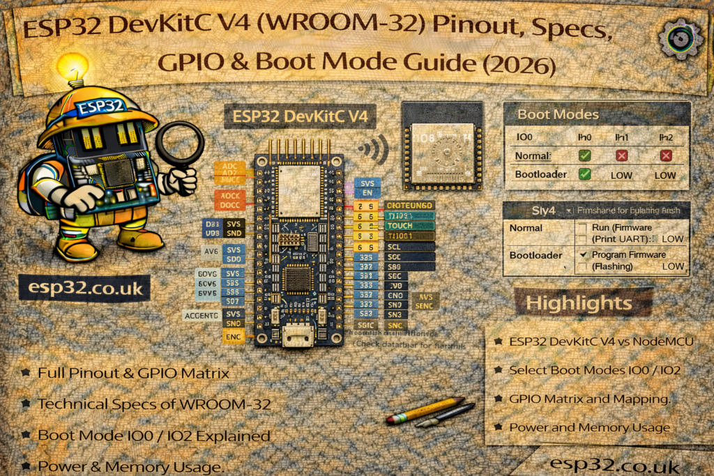
1) What exactly is ESP32-DevKitC V4?
DevKitC V4 is basically a carrier for an ESP32 module (usually ESP32-WROOM). On a typical board you’ll find:
- ESP32 module (WROOM or WROVER)
- USB-to-Serial bridge (CP210x on many official boards; CH340 on many clones)
- Micro-USB connector (power + programming)
- 3.3V regulator
- EN button (reset) and BOOT button (GPIO0)
- Auto-reset/auto-boot circuitry for painless uploading
- Two pin headers exposing most GPIOs
Important: “DevKitC V4” describes the carrier board. The module soldered on it can vary a lot.
2) Under the metal can: Module vs Chip (don’t mix them up)
Think in layers:
- ESP32 chip (SoC): CPU cores + RAM + Wi-Fi/BT radio + peripherals.
- ESP32 module (WROOM/WROVER): the ESP32 chip + external flash (and optionally PSRAM) + antenna/RF matching.
So two DevKitC V4 boards can behave differently even if they “look the same”, because one may have WROVER (PSRAM) while another has WROOM (no PSRAM), or different flash sizes.
3) ESP32 chip deep dive (cores, MHz, wireless, peripherals)
3.1 CPU cores and clock speed
Classic ESP32 uses:
- Dual-core Xtensa LX6 (Core 0 + Core 1)
- Typical max clock: up to 240 MHz
- Runs FreeRTOS underneath (ESP-IDF uses it directly; Arduino uses it indirectly)
What it means in practice
- You can do “real work” while Wi-Fi/Bluetooth stacks run.
- Timing can still jitter under heavy radio activity, but it’s miles ahead of single-core Wi-Fi MCUs.
3.2 On-chip memory (RAM/ROM/RTC memory)
Classic ESP32 includes:
- ~520 KB SRAM on-chip (split internally between instruction RAM and data RAM; some is reserved for system use)
- ROM (bootloader + low-level routines)
- RTC memory (small always-on memory used for deep sleep persistence, plus RTC peripherals)
Reality check: you don’t “get” all internal SRAM as free heap. Wi-Fi, BT, caches, stacks, and drivers consume chunks. Your available heap depends on build settings and features.
3.3 Wireless
Classic ESP32 integrates:
- 2.4 GHz Wi-Fi (802.11 b/g/n)
- Bluetooth Classic + BLE
This is a key “classic ESP32 advantage”: many newer ESP32 variants are BLE-only (no Classic BT).
3.4 Peripherals (the ones you actually use)
ESP32 is loaded. The practical highlights:
- LEDC PWM: excellent PWM for LEDs/motors/servos
- ADC: 12-bit SAR ADC (usable, but not precision-lab quality) ADS115 recommended
- DAC: 2× 8-bit DACs (GPIO25, GPIO26) — handy for audio tones or analog-ish output
- Touch: capacitive touch on multiple pins
- UARTs: multiple serial ports (UART0 used for flashing/logs)
- I²C: flexible pin routing (typical DevKitC: SDA=21, SCL=22)
- SPI: multiple SPI controllers (plus internal flash SPI pins you must not touch)
- I²S: digital audio for microphones/amps/codecs
- RMT: ideal for NeoPixels/WS2812 and IR
- Timers, watchdogs, RTC features, etc.
4) What module do you have (WROOM vs WROVER) and why it matters
4.1 Common module types on DevKitC V4
- ESP32-WROOM-32 (most common): external flash, no PSRAM
- ESP32-WROOM-32U/UE: same but external antenna connector
- ESP32-WROVER: external flash + PSRAM
4.2 Practical differences you’ll actually notice
- PSRAM availability:
- WROVER:
psramFound()is usually true - WROOM: no PSRAM
- WROVER:
- GPIO availability:
- WROVER typically reserves some pins internally for PSRAM (commonly GPIO16/17) so they may not be usable/exposed the same way as WROOM boards.
5) Board variants and clones (how to identify yours)
DevKitC boards in the wild differ in three common ways:
5.1 USB-to-Serial chip
- Official-ish boards often use CP210x family
- Clones commonly use CH340
- Symptoms:
- Different driver requirements on Windows
- Sometimes worse auto-reset behavior on cheap clones
5.2 3.3V regulator and power robustness
Some boards use a chunky regulator (runs warm but stable), others use tiny LDOs that brown out easier.
If you see:
- random resets when Wi-Fi transmits
- brownout detector messages
…suspect power first (cable + USB port + regulator).
5.3 Module markings
Look at the metal can:
- “WROOM” vs “WROVER”
- antenna style (PCB antenna vs u.FL connector)
5.4 Software “identify your board” sketch (recommended)
Paste this into Arduino and it will tell you what you have:
#include <Arduino.h>

void setup() {
  Serial.begin(115200);
  delay(500);

  Serial.println("\n--- ESP32 Board Info ---");
  Serial.printf("CPU freq: %u MHz\n", getCpuFreqMHz());
  Serial.printf("Chip model: %s\n", ESP.getChipModel());
  Serial.printf("Chip rev: %d\n", ESP.getChipRevision());
  Serial.printf("Cores: %d\n", ESP.getChipCores());

  Serial.printf("Flash size: %u bytes\n", ESP.getFlashChipSize());
  Serial.printf("Flash speed: %u Hz\n", ESP.getFlashChipSpeed());

  Serial.printf("Heap free: %u bytes\n", ESP.getFreeHeap());
  Serial.printf("Min heap free: %u bytes\n", ESP.getMinFreeHeap());
  Serial.printf("Max alloc heap: %u bytes\n", ESP.getMaxAllocHeap());

  Serial.printf("PSRAM: %s\n", psramFound() ? "YES" : "NO");
  if (psramFound()) {
    Serial.printf("PSRAM size: %u bytes\n", ESP.getPsramSize());
    Serial.printf("PSRAM free: %u bytes\n", ESP.getFreePsram());
  }
}

void loop() {}
This single snippet answers:
- clock, cores
- flash size + speed
- heap status
- PSRAM presence and size
6) Powering DevKitC V4 (properly)
You can power via:
- Micro-USB (recommended for development)
- 5V pin (regulated 5V input)
- 3V3 pin (regulated 3.3V input — advanced use)
Rules:
- Don’t power from multiple sources at once. Unless they have common Ground.
- Wi-Fi current spikes are real. Use a good cable and a supply with headroom.
7) ESP32 boot process (ROM, strapping pins, boot modes)
Understanding boot is what prevents “mystery dead boards”.
7.1 What happens at reset
- Chip resets (EN toggled low/high)
- ROM bootloader reads strapping pins
- It decides whether to:
- boot your app from flash, or
- enter serial download mode (flashing), or
- change flash voltage / boot settings
- It prints a short ROM message on UART0 (the stuff you often see before your sketch starts)
7.2 Strapping pins (the pins that decide boot behavior)
Classic ESP32 uses several GPIOs as strapping pins. The ones most likely to bite you on DevKitC are:
- GPIO0: download mode selector (BOOT button)
- GPIO12: flash voltage / VDD_SDIO strap (dangerous to pull wrong!)
- GPIO2 / GPIO4 / GPIO5 / GPIO15: other straps used for boot configuration
Rule of thumb (practical, not mythical):
- Avoid attaching external circuits that force these pins HIGH/LOW during reset.
- If you must use them:
- keep external resistors weak (e.g., 100k range)
- avoid large capacitors or LED circuits that “drag” the level at boot
7.3 The “classic mistakes” that break boot
- LED to ground on a strap pin that must be HIGH at boot (or vice versa)
- Relay module input pulling a strap pin hard
- External pull-downs on GPIO0 (board always boots into flashing mode)
- Pulling GPIO12 the wrong way (board fails to boot because flash voltage strap is wrong)
7.4 Boot mode cheat sheet
- Normal boot (run program)
- Don’t press BOOT; just reset/power-up normally.
- Flash/upload mode
- Hold BOOT, tap EN, release EN, then release BOOT.
Many clones need this manual sequence even if auto-reset is present.
8) ESP32 memory map & flash partitions
8.1 RAM types (high-level)
- IRAM: fast internal memory for instructions (interrupts/time-critical code often ends up here)
- DRAM: internal data RAM (heap/stack/data)
- RTC fast/slow memory: persists (or partially persists) across deep sleep depending on usage
- PSRAM (optional): external RAM on WROVER modules (slower than internal, but huge)
Practical tip: use internal RAM for timing-critical buffers; use PSRAM for large buffers and UI assets.
8.2 Flash layout basics
ESP32 flash typically contains:
- Bootloader
- Partition table
- NVS (key-value storage, Wi-Fi credentials, settings)
- PHY init data
- One or two app partitions (for OTA)
- A filesystem partition (SPIFFS or LittleFS) if enabled
8.3 OTA partitions (why two apps exist)
For OTA you need two app slots:
ota_0(current)ota_1(update target)
Flow:
- Download new firmware into the inactive slot
- Mark it as boot target
- Reboot
- If it boots successfully, confirm; otherwise rollback
If you select an Arduino partition scheme with “No OTA”, you only have one app slot and OTA updates won’t fit.
8.4 Arduino partition schemes (what they really mean)
In Arduino IDE (Tools → Partition Scheme), you’ll see options like:
- Default (balanced app + filesystem)
- No OTA (bigger single app)
- Huge APP (maximize app size)
- Minimal SPIFFS (keep tiny filesystem)
- (Sometimes) Minimal / Max OTA depending on core version
How to choose:
- If you want OTA: choose a scheme that includes OTA partitions.
- If you need large web UI files: choose more filesystem space (or use LittleFS).
- If you compile big libraries and run out of app space: choose Huge APP / No OTA.
8.5 Where settings should live (best practice)
- NVS: credentials, calibration constants, small config items
- Filesystem (SPIFFS/LittleFS): HTML/CSS/JS assets, templates, logs, larger files
- PSRAM (if available): runtime buffers (JSON, images, frame buffers)
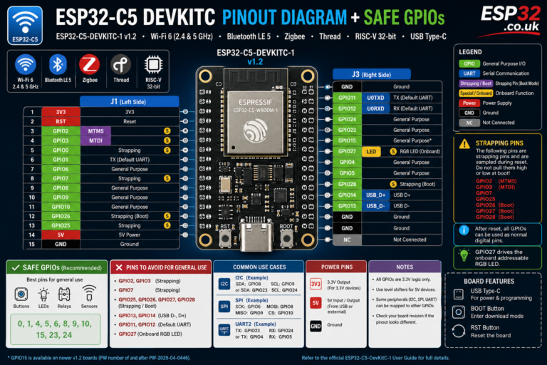
9) ESP32-DevKitC V4 GPIO capability matrix (usable, risky, ADC, touch, DAC)
Check our pinout guide
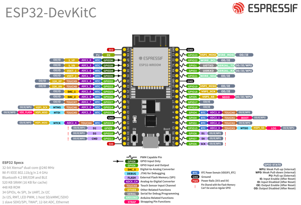
9.1 Pins you should NOT use (flash pins)
These are used internally for SPI flash (and sometimes PSRAM) on the module:
- GPIO6, GPIO7, GPIO8, GPIO9, GPIO10, GPIO11
Treat them as reserved. Don’t connect anything to them.
9.2 Input-only pins (great for ADC, useless for outputs)
- GPIO34, GPIO35, GPIO36, GPIO39 → input only
(Also: no internal pullups/pulldowns on these.)
9.3 ADC1 vs ADC2 (the “Wi-Fi breaks my analogRead” issue)
- ADC1 pins: GPIO32–GPIO39 (recommended for analog sensors)
- ADC2 pins: include GPIO0, 2, 4, 12–15, 25–27
These can conflict when Wi-Fi is active.
If Wi-Fi is on and your analog reading matters → prefer ADC1 pins.
9.4 Quick “best default pins”
Good “general purpose” choices on DevKitC (WROOM) for most projects:
GPIO4, 5, 18, 19, 21, 22, 23, 25, 26, 27, 32, 33
9.5 Capability matrix (practical)
Legend:
- Safe = usually safe for general use
- Strap = affects boot; use carefully
- ADC1/ADC2 = analog input group
- Touch = capacitive touch capable
- DAC = true DAC output
- Input-only = cannot output
| GPIO | Safe for general I/O | Strap at boot | ADC | Touch | DAC | Notes |
|---|---|---|---|---|---|---|
| 0 | ⚠️ | Yes | ADC2 | Touch | — | BOOT button; avoid forcing level at reset |
| 1 | ⚠️ | — | — | — | — | UART0 TX (logs/upload). Don’t use if you need serial |
| 2 | ⚠️ | Yes | ADC2 | Touch | — | Often onboard LED on some boards; boot-sensitive |
| 3 | ⚠️ | — | — | — | — | UART0 RX (upload). Avoid if using Serial |
| 4 | ✅ | ⚠️ (some) | ADC2 | Touch | — | Usually OK; still don’t load heavily at boot |
| 5 | ✅ | ⚠️ (some) | — | — | — | Often used as SPI CS; generally safe |
| 6–11 | ❌ | — | — | — | — | Reserved for flash/PSRAM |
| 12 | ⚠️ | Yes | ADC2 | Touch | — | Flash voltage strap risk; avoid unless you know why |
| 13 | ✅ | — | ADC2 | Touch | — | Common SPI MOSI alternative; generally fine |
| 14 | ✅ | — | ADC2 | Touch | — | Common SPI SCK alternative; generally fine |
| 15 | ⚠️ | Yes | ADC2 | Touch | — | Boot strap; use carefully |
| 16 | ✅* | — | — | — | — | *May be unavailable on WROVER (PSRAM) modules |
| 17 | ✅* | — | — | — | — | *May be unavailable on WROVER (PSRAM) modules |
| 18 | ✅ | — | — | — | — | Great general pin; SPI SCK often |
| 19 | ✅ | — | — | — | — | Great general pin; SPI MISO often |
| 21 | ✅ | — | — | — | — | Common I²C SDA |
| 22 | ✅ | — | — | — | — | Common I²C SCL |
| 23 | ✅ | — | — | — | — | Common SPI MOSI |
| 25 | ✅ | — | ADC2 | — | DAC1 | DAC output pin |
| 26 | ✅ | — | ADC2 | — | DAC2 | DAC output pin |
| 27 | ✅ | — | ADC2 | Touch | — | Good general pin |
| 32 | ✅ | — | ADC1 | Touch | — | Best for analog sensors |
| 33 | ✅ | — | ADC1 | Touch | — | Best for analog sensors |
| 34 | ✅ (input only) | — | ADC1 | — | — | Input only; great ADC |
| 35 | ✅ (input only) | — | ADC1 | — | — | Input only; great ADC |
| 36 | ✅ (input only) | — | ADC1 | — | — | Input only; great ADC |
| 39 | ✅ (input only) | — | ADC1 | — | — | Input only; great ADC |
The strap pins can be used, but they’re where “my board won’t boot” stories come from.
10) Cookbook recipes (Arduino)
Assumptions:
- Board: ESP32 Dev Module
- Serial: 115200
- Use “safe” pins where possible
Recipe 0: Blink (GPIO2)
const int LED_PIN = 2;
void setup() { pinMode(LED_PIN, OUTPUT); }
void loop() { digitalWrite(LED_PIN, HIGH); delay(500); digitalWrite(LED_PIN, LOW); delay(500); }
Recipe 1: Serial debug template
void setup() {
  Serial.begin(115200);
  delay(500);
  Serial.println("\nSerial OK");
}
void loop() {
  static uint32_t t=0;
  if (millis()-t>1000) { t=millis(); Serial.printf("Uptime %lu ms\n",(unsigned long)t); }
}
Recipe 2: Button (GPIO4 to GND)
const int BTN=4;
void setup(){ Serial.begin(115200); pinMode(BTN, INPUT_PULLUP); }
void loop(){ if(digitalRead(BTN)==LOW){ Serial.println("Pressed"); delay(200);} }
Recipe 3: ADC (ADC1 GPIO34)
const int ADC_PIN=34;
void setup(){ Serial.begin(115200); }
void loop(){ Serial.printf("ADC=%d\n", analogRead(ADC_PIN)); delay(500); }
Recipe 4: I²C template (GPIO21/22)
#include <Wire.h>
void setup(){ Serial.begin(115200); Wire.begin(21,22); Serial.println("I2C started"); }
void loop(){}
Recipe 5: PWM fade (GPIO25)
const int PIN=25, CH=0;
void setup(){ ledcSetup(CH, 5000, 8); ledcAttachPin(PIN, CH); }
void loop(){ for(int d=0; d<=255; d++){ ledcWrite(CH,d); delay(5);} for(int d=255; d>=0; d--){ ledcWrite(CH,d); delay(5);} }
Recipe 6: Wi-Fi connect + IP
#include <WiFi.h>
const char* SSID="YOUR_SSID";
const char* PASS="YOUR_PASS";
void setup(){
  Serial.begin(115200); delay(500);
  WiFi.begin(SSID, PASS);
  Serial.print("Connecting");
  for(int i=0;i<30 && WiFi.status()!=WL_CONNECTED;i++){ delay(500); Serial.print("."); }
  Serial.println();
  if(WiFi.status()==WL_CONNECTED){ Serial.print("IP: "); Serial.println(WiFi.localIP()); }
  else Serial.println("WiFi failed");
}
void loop(){}
Recipe 7: Deep sleep 10 seconds
#include "esp_sleep.h"
void setup(){
  Serial.begin(115200); delay(200);
  Serial.println("Sleeping 10s...");
  esp_sleep_enable_timer_wakeup(10ULL*1000000ULL);
  Serial.flush();
  esp_deep_sleep_start();
}
void loop(){}
11) Troubleshooting (quick, real-world)
Upload timeout / can’t connect
Manual boot:
- hold BOOT
- tap EN
- release EN
- release BOOT when upload begins
Random resets during Wi-Fi
- bad cable / weak USB port / weak regulator
- try different cable + powered hub + good 5V supply
ADC nonsense when Wi-Fi starts
- you used ADC2 pins
- move analog sensors to ADC1 (GPIO32–39)
Add-on A: ESP32 strapping pins table (boot levels you must not fight)
ESP32 samples a small set of GPIOs only at reset (power-on or EN reset). Their levels are latched and used to decide boot mode and some hardware settings. After boot, they behave like normal GPIO again — but if you attach hardware that forces the wrong level during reset, the board may not boot.
These are the classic ESP32 strapping pins you’ll meet on DevKitC-style boards: GPIO0, GPIO2, GPIO4, GPIO5, GPIO12 (MTDI), GPIO15 (MTDO).
Strapping pins: practical table (DevKitC V4 / WROOM-style default assumptions)
| Pin | Internal pull (typical) | “Safe default” at boot | What can go wrong | Practical advice |
|---|---|---|---|---|
| GPIO0 | Pull-up (~45k) | HIGH = normal boot; LOW = download/flash mode | Stuck in flashing mode, won’t run sketch | Don’t attach anything that pulls it LOW at reset (except BOOT button). |
| GPIO2 | Often pull-down reported | Don’t force it (leave as board default) | Boot failures if external circuit drives it strongly | Avoid relays/LEDs that clamp it. If you must use it, keep loads light and don’t add hard pulls. |
| GPIO4 | Often pull-down reported | Usually OK if not forced | Rare boot weirdness with heavy loads | Generally safe, but avoid strong pulls/caps that slow rising edges at boot. |
| GPIO5 | Pull-up reported | HIGH | Boot config changes / SDIO-related effects | Treat it as “mostly safe” but don’t hard-pull it LOW at reset. |
| GPIO12 (MTDI) | Pull-down | LOW (selects default 3.3V VDD_SDIO) | If pulled HIGH at reset, VDD_SDIO can go 1.8V, causing flash boot failure | Avoid GPIO12 for general use unless you know exactly why you need it. This is the “mystery brick” pin. |
| GPIO15 (MTDO) | Pull-up reported | HIGH | Boot config/diagnostic behavior changes | Use carefully; avoid hard-pulling it LOW during reset. |
Rule-of-thumb (simple + accurate)
- GPIO0: only pull LOW when flashing.
- GPIO12: don’t touch unless you understand VDD_SDIO.
- The rest (2/4/5/15): you can use them, but avoid external circuits that force a level at reset.
single sentence that saves beginners:
“Avoid GPIO0/2/12/15 for external hardware unless you know boot strapping; especially avoid GPIO12.”
Add-on B: Recommended “known-good” pin map
ESP32 can route many peripheral signals to many pins, which is powerful… and also how people create conflicts without realising it.
Here’s a recommended pin plan that:
- avoids flash pins
- avoids common boot pitfalls
- avoids ADC2 + Wi-Fi conflicts (for analog)
- works nicely on DevKitC V4 WROOM boards
Suggested pin map (DevKitC V4, WROOM module)
I²C (sensors: BME280, ADS1115, PCF8575, OLED)
- SDA = GPIO21
- SCL = GPIO22
Why: it’s the most common convention and doesn’t collide with boot straps.
SPI (VSPI default, best for displays/SD/fast devices)
- SCK = GPIO18
- MISO = GPIO19
- MOSI = GPIO23
- CS = GPIO5 (or GPIO27 if you prefer avoiding strap-ish GPIO5)
Notes:
- Use a separate CS per device.
- If you use an SD card, read the SD pull-up guidance carefully if you involve GPIO12.
UART (extra serial port for GPS, GSM, etc.)
- UART2 TX = GPIO17
- UART2 RX = GPIO16
Notes:
- Great default on WROOM.
- On some PSRAM boards (WROVER variants) these pins may be tied up / not freely available — if readers have WROVER, warn them to verify.
PWM (LEDC) for LEDs, dimming, fans, servo (choose any “safe” GPIO)
Good PWM pins: GPIO4, 5, 18, 19, 21, 22, 23, 25, 26, 27, 32, 33
Analog inputs (recommended: ADC1 only or even better ADS1115)
Use ADC1 pins if Wi-Fi is on:
- GPIO32, 33, 34, 35, 36, 39
Avoid relying on ADC2 for critical analog when Wi-Fi is active (that’s where “analogRead becomes weird” comes from).
DAC outputs (if you need analog-ish output)
- DAC1 = GPIO25
- DAC2 = GPIO26
Add-on C: Stable wiring patterns (what makes projects “not crash”)
This is the section that separates hobby spaghetti from “works every time.”
C1) Power integrity (the #1 cause of random resets)
ESP32 has high current bursts (especially Wi-Fi). Symptoms of weak power:
- random resets, especially when Wi-Fi connects/transmits
- boot loops
- “brownout” messages on serial (sometimes)
Best practice
- Use a good USB cable (data-capable, low resistance).
- If powering externally: use a 5V supply with headroom and a decent regulator.
- Add local bulk capacitance near the board:
- 100 µF electrolytic + 0.1 µF ceramic close to 3V3/GND is a great baseline.
- Don’t power relays/servos/motors from the DevKit’s 3.3V rail.
C2) I²C pull-ups (must exist somewhere)
I²C needs pull-ups. Many breakout boards already have them, which can lead to too-strong pull-up when you connect several boards.
Rule of thumb
- Aim for ~4.7k pull-ups to 3.3V on SDA/SCL as a starting point (effective value depends on how many boards contribute).
- If you see flaky I²C on long wires: reduce pull-up value slightly (e.g. 3.3k) and/or slow the bus.
C3) Buttons: don’t wire “floating inputs”
For buttons:
- wire the button between GPIO and GND
- use
INPUT_PULLUP - add debounce (software or hardware)
Hardware debounce (optional but solid):
- 10k pull-up (if not using internal pull-up)
- 100nF cap to ground at the pin
C4) Relays / solenoids: drive them correctly (and stop resetting your ESP32)
Never drive a relay coil directly from a GPIO.
Use:
- a transistor/MOSFET driver
- flyback diode across the coil
- separate supply for the relay coil (share ground)
Minimum robust pattern
- GPIO → 1k resistor → NPN base (or MOSFET gate)
- flyback diode (1N4148/1N4007) across coil
- relay supply ground tied to ESP32 ground
If you use cheap relay modules:
- many are active LOW
- many include an optocoupler but still share grounds and inject noise
- power them from a separate 5V rail, not from the ESP32 3V3
C5) ADC input protection (don’t kill pins, don’t read noise)
ESP32 ADC is fine for “rough” measurements, but:
- it’s sensitive to noise
- it hates long wires
- it hates being fed >3.3V
Good practice
- keep analog wires short
- Use ADS1115
- add a small RC filter for noisy signals:
- 1k series + 100nF to GND at the ADC pin (tune as needed)
- if measuring higher voltages: use a divider and ensure max < 3.3V
And again: if Wi-Fi is active, prefer ADC1 pins (GPIO32–39).
C6) Long wires and sensors: ground and shielding matters
If a sensor is on long wires:
- run GND alongside signal
- twist pairs (signal+GND) if possible
- avoid running analog lines near switching power wires
- add a decoupling cap at the sensor board too (0.1 µF + maybe 10 µF)
If you do nothing else, follow this:
- Use GPIO21/22 for I²C
- Use GPIO18/19/23 + CS on 5 or 27 for SPI
- Use GPIO16/17 for extra UART (WROOM boards)
- Use GPIO32–39 for analog sensors (ADC1)
- Avoid GPIO6–11 (flash pins)
- Avoid GPIO12 unless you really know why
- If Wi-Fi causes resets: fix power, not code