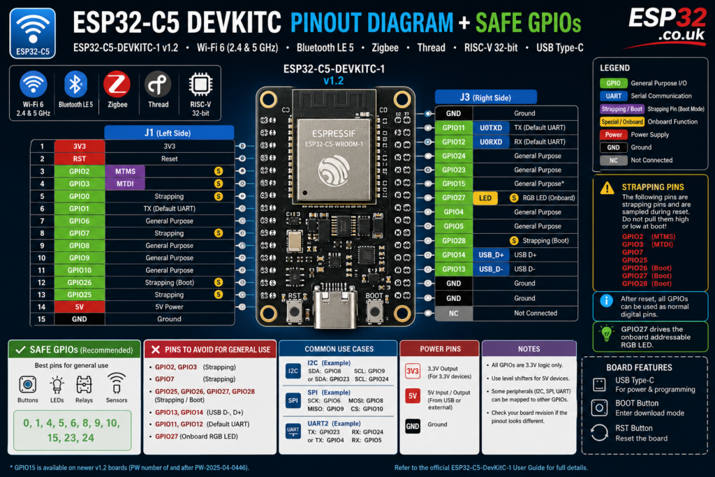
The ESP32-C5 is one of the more interesting newer ESP32 parts because it combines Wi-Fi 6 in 2.4 and 5 GHz, Bluetooth LE, Zigbee, and Thread on one chip, and the ESP32-C5-DevKitC-1 breaks out most available GPIOs on the side headers for breadboard and jumper-wire use. Espressif’s board guide identifies the DevKitC-1 as an entry-level development board based on the ESP32-C5-WROOM-1(U) module, with most I/O brought out to headers J1 and J3.
ESP32-C5 DevKitC-1 quick pinout overview
On the current v1.2 board, the broken-out pins are split across J1 and J3. J1 carries 3V3, RST, GPIO2, GPIO3, GPIO0, GPIO1, GPIO6, GPIO7, GPIO8, GPIO9, GPIO10, GPIO26, GPIO25, 5V, and GND. J3 carries GND, UART TX/GPIO11, UART RX/GPIO12, GPIO24, GPIO23, GPIO15 on newer boards, GPIO27, GPIO4, GPIO5, GPIO28, GPIO13, GPIO14, plus extra grounds and NC pins. The board guide also notes that the addressable onboard RGB LED is driven by GPIO27.
That means the practical user-accessible GPIO set on the board is:
- GPIO0 to GPIO15, with some gaps
- GPIO23 to GPIO28
- plus power, reset, and grounds
Not every one of those is equally safe for “just connect anything” use. Some are tied to boot strapping, some are default USB pins, and some already have board-level jobs.
Visual pin list
J1 side
- 3V3
- RST
- GPIO2
- GPIO3
- GPIO0
- GPIO1
- GPIO6
- GPIO7
- GPIO8
- GPIO9
- GPIO10
- GPIO26
- GPIO25
- 5V
- GND
J3 side
- GND
- GPIO11 / U0TXD
- GPIO12 / U0RXD
- GPIO24
- GPIO23
- GPIO15 on newer v1.2 boards
- GPIO27
- GPIO4
- GPIO5
- GPIO28
- GPIO14 / USB_D+
- GPIO13 / USB_D-
- extra GND pins
Safe GPIOs for general use
If you want the simplest “usually safe” pins for buttons, LEDs, digital sensors, relays, and general GPIO work, the best shortlist on this board is:
- GPIO0
- GPIO1
- GPIO4
- GPIO5
- GPIO6
- GPIO8
- GPIO9
- GPIO10
- GPIO15
- GPIO23
- GPIO24
These are the ones I’d treat as the friendliest pins for most normal projects because, based on Espressif’s current board guide and datasheet, they are broken out and are not the main boot-mode strapping trio, not the default USB pins, and not the onboard RGB LED pin. That is a practical recommendation from the published pin roles, not a direct Espressif sentence. The official sources you do need to respect are that GPIO25, GPIO26, GPIO27, GPIO28, GPIO7, MTMS/GPIO2, and MTDI/GPIO3 are strapping pins, while GPIO13 and GPIO14 are USB D- and D+, and GPIO27 drives the onboard RGB LED.
Pins to avoid for “safe GPIO” lists
These are the ones I would not present as carefree general-purpose pins:
- GPIO2 — strapping pin via MTMS
- GPIO3 — strapping pin via MTDI
- GPIO7 — strapping pin
- GPIO25
- GPIO26
- GPIO27
- GPIO28
- GPIO13 — USB_D-
- GPIO14 — USB_D+
- GPIO11 / GPIO12 if you want to keep the default UART console free
- GPIO27 also because it is tied to the board RGB LED
This does not mean those pins are unusable. It means they are the wrong pins to recommend casually in a “safe GPIOs” article because they come with caveats that beginners often learn the hard way.
Strapping pins: the main thing that can bite you
Espressif’s hardware design guide and datasheet are very clear that the ESP32-C5 has strapping pins sampled at startup or reset. The relevant strapping pins are GPIO25, GPIO26, GPIO27, GPIO28, GPIO7, MTMS, and MTDI, and on the DevKitC-1 those MTMS and MTDI signals are broken out as GPIO2 and GPIO3. After reset they can be used as normal GPIOs, but at boot they influence chip configuration, and the boot mode itself is controlled by GPIO26, GPIO27, and GPIO28. The default SPI boot configuration relies on GPIO28 being high at reset.
Translated into plain English:
if you hang the wrong external circuit on one of those pins and it drags the level up or down during reset, your board may stop booting normally, enter a download mode, or behave inconsistently. That is why these pins should not be your first choice for buttons, relays, pull-heavy sensor outputs, or anything that forces a level during power-up.
USB pins
The DevKitC-1 board guide shows:
- GPIO14 = USB_D+
- GPIO13 = USB_D-
If you plan to use the native USB port for flashing, USB communication, or JTAG-style workflows, avoid treating GPIO13 and GPIO14 like random spare pins. They may be available as GPIOs in some project setups, but for a “safe pins” guide they belong in the caution category.
UART pins
The board guide maps:
- GPIO11 = U0TXD
- GPIO12 = U0RXD
These are handy if you want the default UART, but they are also the ones you are most likely to want for logging, flashing workflows, or serial debugging. So they are usable, just not ideal if you want to keep the board easy to debug while developing.
Onboard RGB LED pin
Espressif’s board guide states the onboard addressable RGB LED is driven by GPIO27. That means GPIO27 is a bad choice for “clean, free GPIO” recommendations unless you intentionally want to reuse or disable the onboard LED. It is also one of the chip’s strapping pins, which makes it an even worse candidate for beginner-safe use.
Recommended pins by purpose
Best pins for digital inputs or outputs
Use these first:
- GPIO0
- GPIO1
- GPIO4
- GPIO5
- GPIO6
- GPIO8
- GPIO9
- GPIO10
- GPIO15
- GPIO23
- GPIO24
These are the least awkward mix for LEDs, buttons, relays, PIR sensors, reed switches, buzzers, and logic-level signals, based on the board’s published pin roles.
Good pins for I2C
Because the ESP32 GPIO matrix lets peripherals be routed flexibly, you are not locked to one hardwired I2C pair. A practical choice would be:
- SDA: GPIO8
- SCL: GPIO9
or
- SDA: GPIO23
- SCL: GPIO24
Those suggestions are an inference from the GPIO matrix flexibility plus the pin breakout list, not a direct official “recommended pair.” They are sensible because they avoid strapping pins, USB pins, and the onboard LED pin.
Good pins for SPI
Again, the GPIO matrix gives flexibility, but a clean software SPI or remapped SPI setup could use:
- SCK: GPIO6
- MOSI: GPIO8
- MISO: GPIO9
- CS: GPIO10 or GPIO23
You can also see FSPI-related alternate functions on several pins in the board guide, but for a safe beginner article, the bigger message is simply to pick free non-strapping pins and keep USB pins alone unless you know why you are repurposing them.
Good pins for a second UART
If you want a peripheral UART and want to leave the default console pins alone, a practical software choice is any spare safe pair such as:
- TX: GPIO23
- RX: GPIO24
or
- TX: GPIO4
- RX: GPIO5
Power pins
The board exposes both:
- 3V3
- 5V
- GND
The 3V3 pin is for 3.3 V peripherals and logic. The 5V pin is the 5 V supply rail. Keep in mind the ESP32-C5 GPIOs are 3.3 V logic, so even if a module is powered from 5 V, its signal lines still need to be safe for 3.3 V GPIO unless level-shifted. The board guide confirms the board uses a 5 V to 3.3 V regulator and exposes both rails.
Simple safe GPIO table
| GPIO | Safe for general use? | Notes |
|---|---|---|
| GPIO0 | Yes | General use |
| GPIO1 | Yes | General use |
| GPIO2 | Caution | Strapping pin via MTMS |
| GPIO3 | Caution | Strapping pin via MTDI |
| GPIO4 | Yes | Good general pin |
| GPIO5 | Yes | Good general pin |
| GPIO6 | Yes | Good general pin |
| GPIO7 | Caution | Strapping pin |
| GPIO8 | Yes | Good general pin |
| GPIO9 | Yes | Good general pin |
| GPIO10 | Yes | Good general pin |
| GPIO11 | Caution | Default UART TX |
| GPIO12 | Caution | Default UART RX |
| GPIO13 | Caution | USB_D- |
| GPIO14 | Caution | USB_D+ |
| GPIO15 | Yes | Good general pin on newer v1.2 boards |
| GPIO23 | Yes | Good general pin |
| GPIO24 | Yes | Good general pin |
| GPIO25 | Caution | Strapping pin |
| GPIO26 | Caution | Strapping pin, boot-related |
| GPIO27 | Caution | Strapping pin and onboard RGB LED |
| GPIO28 | Caution | Strapping pin, boot-related |
A note about board revision
Espressif’s current v1.2 user guide notes that for boards with PW number of and after PW-2025-04-0446, J1 and J3 functions were updated, and the header block in the current guide reflects that newer layout. That means some pinout images floating around online may not match your exact board revision.
So if you are making a pinout diagram for your site, label it specifically as:
That avoids the usual confusion when someone compares your graphic with an older board print or an outdated marketplace image.
Final thoughts
The ESP32-C5 DevKitC is straightforward once you separate the pins into two groups: safe everyday GPIOs and pins with caveats. The safest practical pins for most projects are GPIO0, 1, 4, 5, 6, 8, 9, 10, 15, 23, and 24. The pins to treat carefully are the strapping pins, the USB pins, the default UART pins, and GPIO27 because of the onboard RGB LED.