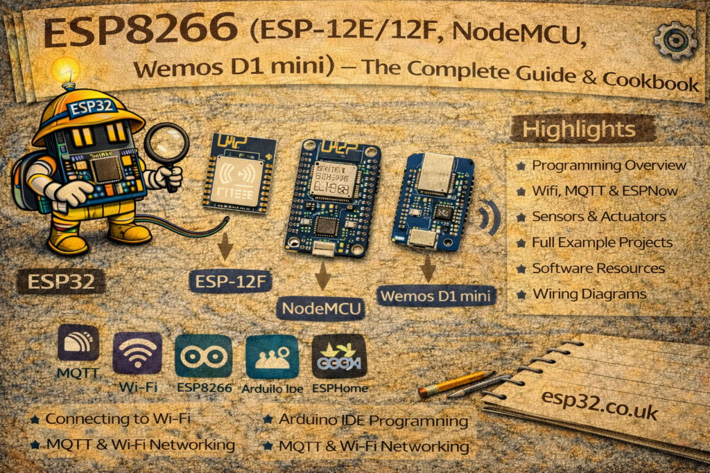
This guide explains the most common ESP8266AliExpress price variants (ESP-01AliExpress price, ESP-12E/F, NodeMCUAliExpress price and D1 mini) and shows their pinouts, safe GPIOs, and boot-sensitive pins to avoid.
The ESP8266AliExpress price started life as a tiny Wi-Fi module but quickly became a full microcontroller platform. Under the metal cans, almost all modules use the same chip (ESP8266EX) – what changes is:
- How many GPIO pins are brought out
- Antenna type (PCB vs ceramic vs u.FL)
- Form factor (bare module vs dev board)
Quick verdict: choose a D1 Mini for the smallest general-purpose development board, NodeMCUAliExpress price when easy USB setup and more breadboard space matter, an ESP-12F for custom PCBs, and an ESP-01S only when two boot-sensitive GPIOs are enough.
- ESP-01 / ESP-01S – 8-pin “stick” module
- ESP-12E / ESP-12F (and ESP-07) – 22-pad SMD modules
- NodeMCU dev board – ESP-12E on a USB dev board
- Wemos D1 mini – small, breadboard-friendly dev board
And we’ll summarise pinouts and which pins are “safe” to use.
⚠️ ESP8266 GPIOs use 3.3 V logic. Feeding 5 V directly into a GPIO can damage the chip.
ESP-01 and ESP-01S Pinout
The ESP-01 is the original “blue board” most people saw first: a tiny module with only 8 pins broken out. It’s cheap and widely used in legacy designs.
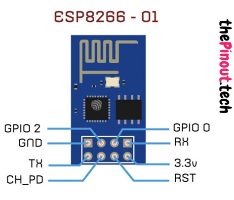

Typical pinout (viewed from top, pins pointing down)
| Pin | Name | Function |
|---|---|---|
| 1 | GND | Ground |
| 2 | GPIO2 | I/O, also affects boot mode |
| 3 | GPIO0 | I/O, boot-mode / flash pin |
| 4 | RXD0 | UART0 RX |
| 5 | TXD0 | UART0 TX |
| 6 | CH_PD / EN | Chip enable (pull HIGH to run) |
| 7 | RST | Reset (active LOW) |
| 8 | VCC | 3.3 V power |
Practical notes:
- Usable GPIOs in normal projects: GPIO0, GPIO2 (both have boot-mode roles)
- To flash firmware, you usually:
- Hold GPIO0 LOW at reset → enter bootloader
- Use TXD0/RXD0 as serial connection
- Very limited number of I/O pins makes ESP-01 a pain for bigger projects. Great as a Wi-Fi modem or for very small nodes.
ESP-12E, ESP-12F and ESP-07 Pinouts
Modules like ESP-12E, ESP-12F and ESP-07 expose almost all usable pins of the ESP8266EX. They’re metal-shielded SMD modules used on dev boards like NodeMCU.
They all share a very similar core pinout; ESP-12E/F adds an extra bottom row mainly for flash pins.
High-level features of the ESP-12 class:
- 17 GPIOs total on the chip, ~11–13 usable on typical modules
- 1× 10-bit ADC (A0)
- PCB antenna (ESP-12), ceramic antenna (ESP-07)
Typical ESP-12E pin groups:
- Power & control:
VCC,GND,EN/CH_PD,RST - UART0:
TXD0(GPIO1),RXD0(GPIO3) – default programming / logging port - SPI flash pins:
GPIO6–GPIO11– used internally, don’t touch - General GPIOs:
GPIO0, 2, 4, 5, 12, 13, 14, 15, 16 - ADC:
TOUTorADC0– 0–1.0 V max
Example bare ESP-12E pinout:
- “Safe” GPIOs most people use:
- GPIO4, GPIO5, GPIO12, GPIO13, GPIO14 → best general I/O
- GPIO16 can wake the ESP8266 from deep sleep only when it is wired to RST.
- Boot-sensitive pins:
- GPIO0, GPIO2, GPIO15 control boot mode – must be at the right level on reset.
- GPIO1/3 used for UART – toggled during boot.
NodeMCU ESP8266 Pinout
NodeMCU boards like NodeMCU v1.0 (ESP-12E) take an ESP-12 module and add:
- USB-to-serial (CP2102/CH340)
- 3.3 V regulator
- Auto-reset / auto-flash circuitry
- Breadboard-friendly pins labelled D0, D1, D2… instead of raw GPIO numbers
Typical NodeMCU ESP-12E dev board pinout:
| Board label | ESP8266 GPIO | Notes |
|---|---|---|
| D0 | GPIO16 | No PWM; wire D0 to RST for deep-sleep wake |
| D1 | GPIO5 | I²C SCL (by convention) |
| D2 | GPIO4 | I²C SDA (by convention) |
| D3 | GPIO0 | Boot mode pin, pulled-up |
| D4 | GPIO2 | Boot mode pin, on-board LED on many |
| D5 | GPIO14 | HSPI CLK |
| D6 | GPIO12 | HSPI MISO |
| D7 | GPIO13 | HSPI MOSI |
| D8 | GPIO15 | Boot mode pin, pulled-down |
| RX | GPIO3 | UART0 RX (Serial) |
| TX | GPIO1 | UART0 TX (Serial) |
| A0 | ADC0 | Board-dependent divider; commonly about 3.2–3.3 V max. Bare ESP8266 TOUT is 1.0 V max. |
Good defaults on NodeMCU:
- I²C →
D2 (GPIO4)SDA,D1 (GPIO5)SCL - SPI →
D5 (GPIO14)SCK,D6 (GPIO12)MISO,D7 (GPIO13)MOSI,D8 (GPIO15)CS - Avoid using
D3 (GPIO0),D4 (GPIO2),D8 (GPIO15)for things that pull hard HIGH/LOW at boot.
Wemos/LOLIN D1 Mini Pinout
The Wemos D1 mini is a very compact dev board with an ESP-12 module, micro-USB and 3.3 V regulator. It exposes 11 usable GPIOs and is extremely popular in DIY and Home Assistant projects.
Typical D1 mini pin mapping:
| Label | GPIO | Typical use |
|---|---|---|
| D0 | GPIO16 | Wire D0 to RST for deep-sleep wake; no PWM |
| D1 | GPIO5 | I²C SCL |
| D2 | GPIO4 | I²C SDA |
| D3 | GPIO0 | Boot pin, input w/PU |
| D4 | GPIO2 | Boot pin, on-board LED |
| D5 | GPIO14 | SPI SCK |
| D6 | GPIO12 | SPI MISO |
| D7 | GPIO13 | SPI MOSI |
| D8 | GPIO15 | Boot pin (pulled-down) |
| RX | GPIO3 | UART0 RX |
| TX | GPIO1 | UART0 TX |
| A0 | ADC0 | 3.2 V max on the official D1 Mini |
Notes:
- Only one ADC channel (A0).
- D0 (GPIO16) lacks the usual interrupt, PWM, I²C and OneWire support; wire D0 to RST for deep-sleep wake.
- Don’t tie
D3, D4, D8to random stuff that changes the boot levels.
Other ESP8266 Module Variants
There are more SMD modules, but they’re all the same chip plus different antennas / footprints:
- ESP-05 – tiny module with just UART pins and power (like ESP-01 but even more limited).
- ESP-07 – similar pinout to ESP-12 but with ceramic antenna and u.FL connector.
- ESP-201 / ESP-14 – older / less common modules with their own pinouts.
The main differences are:
- How many GPIOs are broken out
- Antenna type (PCB vs ceramic vs external connector)
- Footprint and shield size
The actual SoC (ESP8266EX) and its GPIO roles are the same across all of them.
Safe GPIOs and Boot Pins
Because of boot-mode strapping, some pins must be at defined levels during reset. The classic rule from the ESP8266 pinout references:
Boot strapping pins:
- GPIO0
- GPIO2
- GPIO15
Valid boot from flash requires:
GPIO0 = HIGHGPIO2 = HIGHGPIO15 = LOW
So:
- Don’t pull GPIO0 or GPIO2 hard LOW at boot.
- Don’t pull GPIO15 HIGH at boot.
- You can use them after boot, but avoid big loads or things that force the wrong level during reset.
Generally safe GPIOs on ESP-12 / NodeMCU / D1 mini:
GPIO4, GPIO5, GPIO12, GPIO13, GPIO14, GPIO16