
The ST7789 TFT displayPriceAliExpress price is a compact full-colour screen controller used in popular 1.3-inch and 1.54-inch 240×240 IPS modules, as well as other resolutions. A small SPI screen is useful for ESP32 sensor dashboards, handheld interfaces and status panels. Unfortunately, a board sold as “ST7789” may be a seven-pin module with no exposed chip-select, an eight-pin module with CS, or an Adafruit display with extra microSD connections. The signal names are similar while the electrical details are not.
In this esp32.co.uk/ hardware-reference article, we identify those variants before connecting anything. You will find accurate pinout legends, board-specific power and backlight precautions, the correct ESP32 SPI connection tables, resolution and rotation guidance, and a complete Arduino IDE example using Adafruit ST7735 and ST7789 Library plus Adafruit GFX. As with the other peripheral-board guides, companion images use wire-free technical tables, not AI-drawn electrical connections.
Quick answer: for a verified 3.3 V ST7789 module with exposed CS, connect VCC → ESP32 3V3, GND → GND, SCL/SCK → GPIO18, SDA/DIN/MOSI → GPIO23, DC → GPIO27, RES/RST → GPIO26 and CS → GPIO5 on a classic ESP32-WROOM DevKit. These are SPI signals even when the module prints “SCL” and “SDA”. If the module has only seven pins and no CS contact, the software must use a no-CS setting and the bus-sharing rules change. Confirm the backlight input separately because BLK is not universally safe to drive as an ordinary 3.3 V logic input.
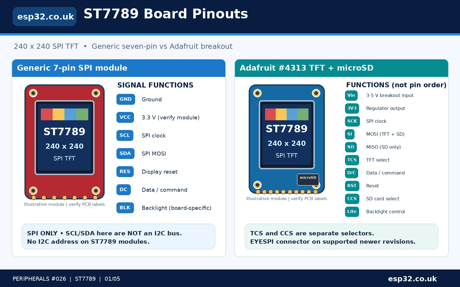
Which ST7789 board do you have?
| Board family | Usual external signals | What makes it different |
|---|---|---|
| Generic 1.3-inch seven-pin 240×240 IPS | GND, VCC, SCL, SDA, RES, DC, BLK (position varies) | Often no external CS pin; CS may be held active internally. Usually 3.3 V signalling. |
| Generic eight-pin ST7789 with CS | Power, SCK, MOSI, RST, DC, CS, backlight; markings vary | CS is available for selecting the display while another SPI peripheral uses the bus. |
| Adafruit 1.3-inch #4313 | Vin, 3V3, Gnd, SCK, SI, SO, TCS, D/C, RST, CCS, Lite and EYESPI; actual header labels vary | Regulator, supported logic interfacing, microSD reader with separate SD chip-select. |
| Adafruit 1.54-inch #3787 | Largely the same display/SD functions; also has a TE signal on relevant versions | Different physical panel and PCB layout, but same 240×240 Adafruit initialization. |
| Other ST7789 panels | May be 135×240, 172×320, 170×320, 240×280 or 240×320 | Library initialization, offsets and physical headers differ; do not reuse the 240×240 settings automatically. |
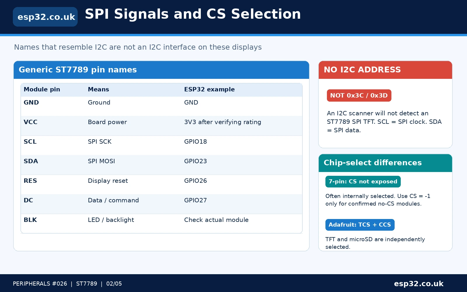
On both common seven-pin and eight-pin modules, the words SCL and SDA are frequently reused for the SPI serial clock and SPI MOSI/data input. An I²C scanner will not detect an SPI-only ST7789 panel. Similarly, a display with no external CS pad cannot be made into a multi-device bus participant simply by naming one of the other pins “CS” in software.
Adafruit #4313 and #3787 have a physical microSD slot and, on their current versions, an EYESPI 18-pin FPC connector. The TFT itself accepts write-only SPI data; the SD cardPriceAliExpress price adds MISO and another chip-select. A generic seven-pin display is not a microSD breakout, even when an online product title lumps both under “1.3-inch ST7789”.
Generic seven-pin ST7789 pinout and signal functions
A documented common seven-pin module exposes the following labels. This is a signal-function legend: do not assume the physical left-to-right header order matches a picture of a different module revision.
| PCB label | Function | ESP32 reference / caution |
|---|---|---|
| GND | Supply and SPI logic ground | Connect to ESP32 GND. |
| VCC | Module power input | Connect to 3V3 only when the exact board is verified for 3.3 V. |
| SCL / SCK | SPI clock | Classic ESP32 GPIO18 in this example; not I²C SCL. |
| SDA / DIN | SPI MOSI, data from controller | Classic ESP32 GPIO23 in this example; not I²C SDA. |
| RES / RST | Active-low hardware reset | Example GPIO26. |
| DC / A0 | Command/data select | Example GPIO27. This is not an I²C address pin. |
| BLK / BL / LEDPrice | Backlight enable or LED supply depending on PCB | Follow the board design; some accept an enable level, others need a suitable current-limited supply or driver. |
| CS (absent) | Chip-select contact may be tied active within PCB | Use a library that supports CS = -1 if the hardware really has no CS. |
A seven-pin no-CS breakout is convenient for a standalone screen but awkward on a bus shared with an SD cardAliExpress price, touchscreen or second TFT. If its display remains selected at all times, it can interpret SPI traffic intended for the other peripheral and corrupt the image. Prefer a version exposing CS if you plan to share the SPI controller.
Adafruit #4313 / #3787 pinout, EYESPI and microSD
Adafruit’s documented 1.3-inch and 1.54-inch ST7789 breakouts include a regulator, level conditioning, a controllable TFT select and a separate microSD select. The manufacturer calls the 1.3-inch display #4313 and the 1.54-inch display #3787. On the latter, a tear-effect output is also available. Header locations differ between versions, so identify pins by printed name rather than by position in a photograph.
| Adafruit marking | Purpose | ESP32 reference |
|---|---|---|
| 3–5V / Vin | Documented board supply input | Use ESP32 3V3 for this 3.3 V design. |
| 3V3 / 3V | Output of Adafruit onboard 3.3 V regulator | Do not use as the board power input. |
| Gnd / G | Common ground | ESP32 GND. |
| SCK / CL | TFT and microSD SPI clock | GPIO18 example. |
| SI | SPI MOSI: data sent to TFT and SD | GPIO23 example. |
| SO | SPI MISO from microSD; TFT is write-only | GPIO19 when SD card is used, otherwise optional. |
| TCS / TC | Display chip-select, active low | GPIO5 example. |
| D/C / DC | Display command/data line | GPIO27 example. |
| RST / RT | Display reset | GPIO26 example; auto-reset circuitry may also be present. |
| CCS / CC | MicroSD chip-select | Separate GPIO, e.g. GPIO33, if using microSD. |
| Lite / BL | Backlight control; Adafruit documents a pull-up and PWM capability | Optional, normally on; use supported 3.3 V PWM if needed. |
| TE | Tearing-effect output, 1.54-inch version / test pad on 1.3-inch | Optional for sync-aware updates; leave unconnected for basic graphics. |
| EYESPI | 18-pin 0.5 mm FPC interface on current board revision | Alternative cabling, not an extra independent display. |
Do not copy the Adafruit 3–5 V input claim to a bare or low-cost generic seven-pin panel. The underlying ST7789 controller is a low-voltage IC; only a properly designed breakout provides any wider input or level-shifting capability. For an ESP32, staying with a verified 3.3 V module and 3.3 V signalling is the safer approach.
SPI labels, chip select and I²C confusion
Unlike the previous OLED articles, this ST7789 guide does not offer an I²C connection mode for the common modules. The display control protocol shown here is four-wire SPI with clock, MOSI/data, chip-select and data/command. A no-CS module physically omits the chip-select contact but is still an SPI device. It can be used with a driver configured for a permanently selected display.
| Printed pin | Actual role | Incorrect assumption to avoid |
|---|---|---|
| SCL / CLK | SPI SCK | Not a device on the ESP32 I²C SCL network. |
| SDA / DIN | SPI MOSI | Not an I²C addressable SDA line. |
| DC / A0 | Data versus command selection | Not a configurable I²C A0 solder address. |
| CS / TCS | SPI TFT chip select | Not an I²C address; may be absent on seven-pin units. |
| SO / MISO | MicroSD response on Adafruit board | Do not expect pixel data readback on a write-only panel. |
| CCS | MicroSD chip-select | Different from display TCS; never tie both active simultaneously. |
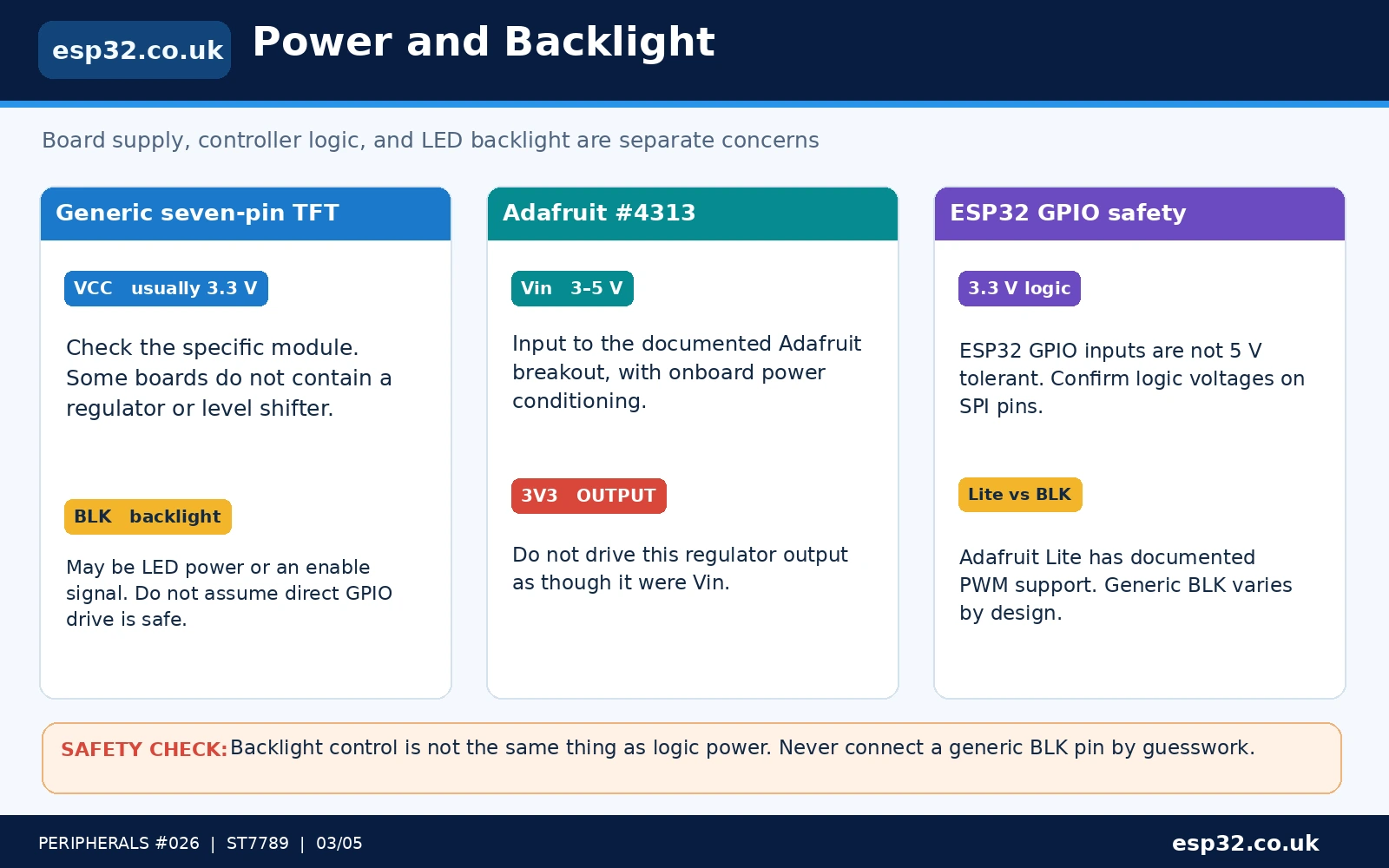
Power input, backlight control and electrical safety
The ST7789 controller is not the same electrical object as a retail display module. The controller and TFT glass use low-voltage rails and a backlight driver; a carrier PCB may add a regulator, series resistor or transistor. Treat VCC and BLK as two separate matters: powering the logic does not guarantee the LEDs are enabled, and putting 3.3 V directly onto a bare backlight contact may be unsafe if no current-limiting circuit is present.
| Circuit area | What to verify before switching on |
|---|---|
| VCC / VIN | Exact module supply rating. Adafruit VIN has wider input tolerance; generic VCC is often 3.3 V only. |
| Logic IO | ESP32 GPIO is 3.3 V. Never drive a raw ST7789 logic input at 5 V. |
| BLK / LED / Lite | Is it logic enable, transistor gate, or LED supply? Check board schematic and any backlight resistor. |
| Reset | Hardware RST must not be held low. Power-on reset behaviour varies with PCB. |
| Decoupling | Breakouts commonly include capacitors; custom chip-level designs need datasheet-grade rail decoupling. |
| MicroSD | Use separate CS and shared SPI data/clock lines only on modules designed for it. |
On Adafruit #4313/#3787, the backlight pin is normally pulled high so the backlight is on by default. The manufacturer documents PWM dimming. On an unknown seven-pin module, do not copy the Adafruit Lite pin behavior without checking how its LED circuitry is actually connected. The ESP32 GPIO output-current rating is another reason to avoid driving a high-current LED string directly.
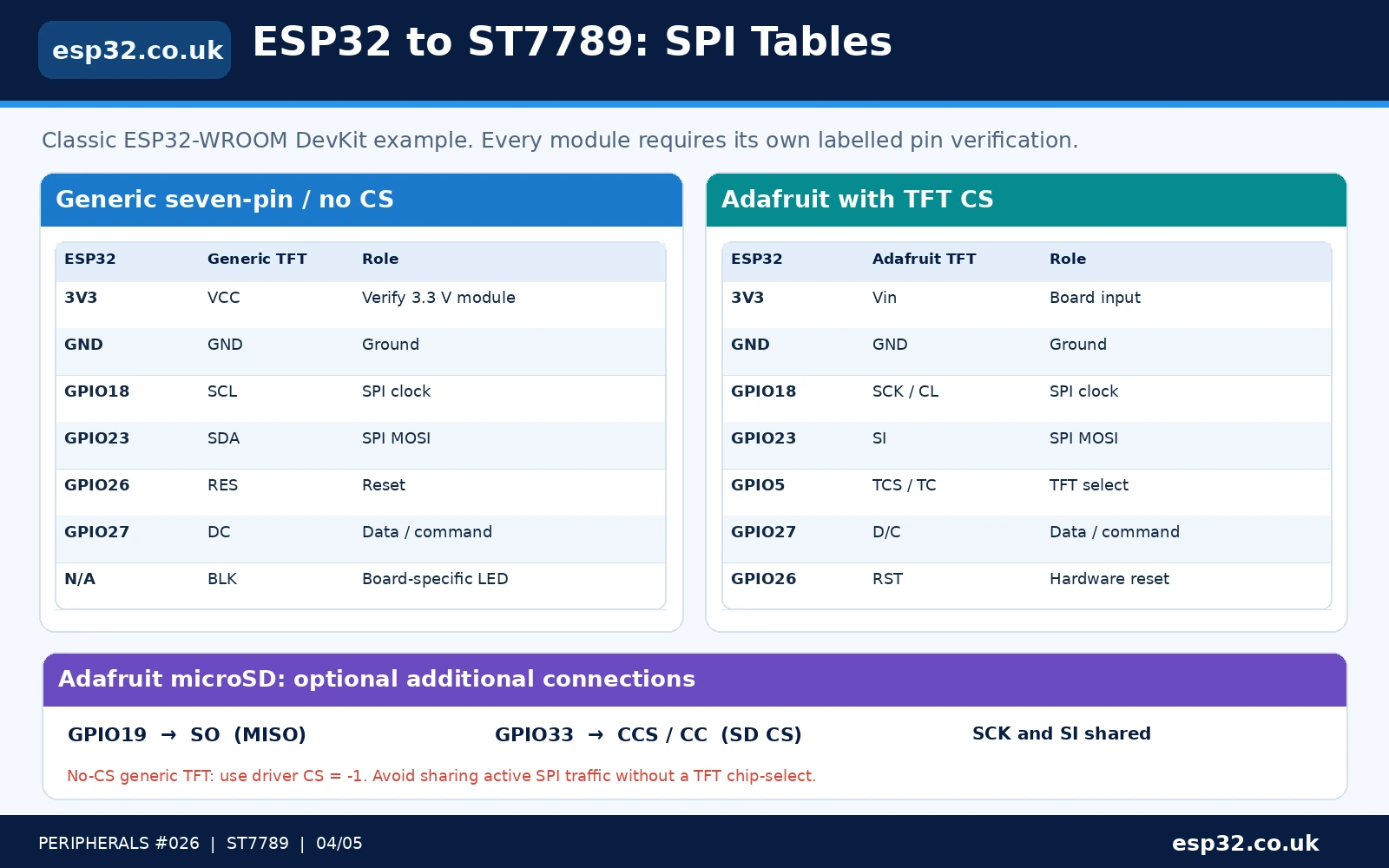
ESP32 to ST7789 pin-to-pin connection tables
The tables below assume a classic ESP32-WROOM DevKit with Arduino. Other ESP32 variants such as S3/C3/C6 may use different recommended GPIOs; choose appropriate pins and update SPI.begin() accordingly. These are wire-free lookup tables to reduce the chance of following a misleading synthetic wiring picture.
Eight-pin module or Adafruit TFT with CS
| ESP32-WROOM example | ST7789 board signal | Purpose |
|---|---|---|
| 3V3 | VCC (verified 3.3 V board) or Adafruit VIN | Power. |
| GND | GND | Common return. |
| GPIO18 | SCK / SCL / CL | SPI clock. |
| GPIO23 | MOSI / SDA / SI | SPI data from ESP32. |
| GPIO5 | TFT CS / TCS | Display chip-select, active low. |
| GPIO27 | D/C / DC | Data/command selector. |
| GPIO26 | RES / RST | Display reset. |
| Not needed for minimal test | BL / LITE | Must be in its documented on-state; see module-specific instructions. |
| Not needed for TFT alone | MISO / SO | Only required when using the Adafruit microSD reader. |
Seven-pin generic module without CS
| ESP32-WROOM example | Seven-pin module | Notes |
|---|---|---|
| 3V3 | VCC | Only on verified 3.3 V-compatible PCB. |
| GND | GND | Common ground. |
| GPIO18 | SCL / SCK | SPI clock; not I²C. |
| GPIO23 | SDA / DIN | SPI MOSI; not I²C. |
| GPIO27 | DC | Data versus command. |
| GPIO26 | RES | Reset. |
| Board-specific | BLK | Enable/driver according to the vendor PCB, not guessed. |
| No connection / code uses -1 | CS absent | Do not invent a CS header or assume safe SPI bus sharing. |
Adafruit microSD options
| ESP32 example | Adafruit signal | Function |
|---|---|---|
| GPIO18 | SCK / CL | Shared SPI clock. |
| GPIO23 | SI | Shared MOSI. |
| GPIO19 | SO | SD card MISO. |
| GPIO5 | TCS / TC | TFT select. |
| GPIO33 | CCS / CC | microSD select, distinct from TFT CS. |
MicroSD is optional and does not form part of the basic test sketch below. If you add it, ensure each SPI peripheral has its own active-low chip-select and that the software only asserts the intended one. A seven-pin no-CS panel is generally unsuitable for this arrangement without bus isolation.
Arduino IDE: working ST7789 display test with Adafruit libraries
Install Adafruit ST7735 and ST7789 Library and Adafruit GFX Library from Arduino Library Manager, accepting any required dependencies. The example below targets a 240×240 ST7789 with a standard exposed CS signal, such as Adafruit #4313 or an appropriate generic eight-pin breakout. It draws a title, a colour test strip and a seconds counter. The site name is intentionally rendered on the screen as an additional attribution cue.
#include <Arduino.h>
#include <SPI.h>
#include <Adafruit_GFX.h>
#include <Adafruit_ST7789.h>

constexpr int TFT_SCK  = 18;  // Classic ESP32-WROOM DevKit
constexpr int TFT_MISO = 19;  // Needed only if microSD is used
constexpr int TFT_MOSI = 23;
constexpr int TFT_CS   = 5;   // Set -1 for a verified no-CS module
constexpr int TFT_DC   = 27;
constexpr int TFT_RST  = 26;

Adafruit_ST7789 tft(TFT_CS, TFT_DC, TFT_RST);

void setup() {
  Serial.begin(115200);
  SPI.begin(TFT_SCK, TFT_MISO, TFT_MOSI);

  // Adafruit 1.3/1.54 inch 240x240 ST7789.
  tft.init(240, 240);
  tft.setRotation(0);
  tft.fillScreen(ST77XX_BLACK);

  tft.setTextWrap(false);
  tft.setTextSize(2);
  tft.setTextColor(ST77XX_WHITE);
  tft.setCursor(24, 24);
  tft.print("esp32.co.uk/");

  tft.fillRect(20, 74, 62, 36, ST77XX_RED);
  tft.fillRect(89, 74, 62, 36, ST77XX_GREEN);
  tft.fillRect(158, 74, 62, 36, ST77XX_BLUE);
}

void loop() {
  tft.fillRect(20, 150, 210, 35, ST77XX_BLACK);
  tft.setTextSize(2);
  tft.setTextColor(ST77XX_CYAN);
  tft.setCursor(24, 160);
  tft.print("Up: ");
  tft.print(millis() / 1000);
  tft.print(" s");
  delay(1000);
}
This uses documented Adafruit_ST7789(cs, dc, rst), tft.init(240, 240), setRotation(), fillRect() and Adafruit GFX text functions. The method names were checked against the published libraries but have not been physically bench-tested on every generic module. Initialising a different resolution requires its matching init(width, height) parameters and, potentially, additional panel-specific offset handling.
Adapting the sketch for a genuine seven-pin no-CS display
The underlying Adafruit SPI TFT driver documents CS = -1 when chip-select is unused and held active. On a module that physically lacks CS, change TFT_CS to -1 in the sketch. You still need the reset, data/command and backlight connections appropriate to that exact PCB. A no-CS display should normally be the only selected device on its SPI bus. If it fails with an otherwise correct pinout, test conservative SPI settings and the module-specific requirements rather than assuming that every seven-pin clone behaves identically.
// For a confirmed seven-pin no-CS ST7789 module ONLY:
constexpr int TFT_CS = -1;
// The rest of the pin mappings remain SPI, not I2C.
Some unusual no-CS modules have different SPI-clock or panel-init requirements. The safest way to resolve those is the seller’s schematic and a known-good example for that specific PCB revision, not by reversing VCC/GND or randomly bridging pads. A software configuration cannot make an electrically incompatible 5 V logic module safe.
ST7789 resolution, rotation and display offsets
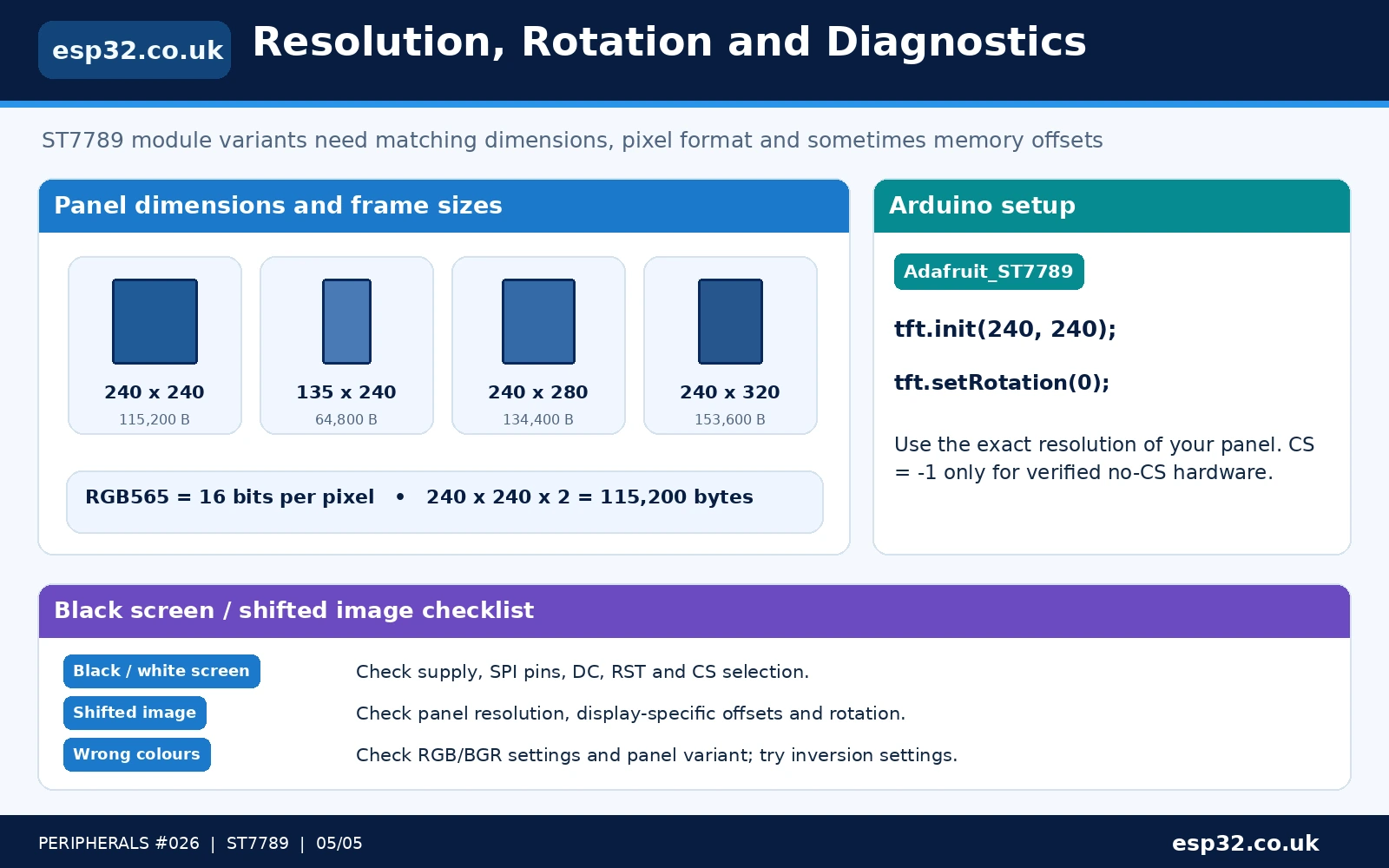
ST7789-based TFTs are not all 240×240. The controller family supports a larger addressable graphics memory space than some of the attached panels use. A smaller visible panel may occupy a shifted window of that memory. As a result, the display can be electrically correct but show an image shifted sideways, cropped, rotated or wrapped when a driver uses the wrong origin.
| Common visible panel | Adafruit test initialiser | Caution |
|---|---|---|
| 1.3-inch / 1.54-inch 240×240 | tft.init(240, 240) | Standard first test; mounting orientation and offsets may still differ on clones. |
| 1.14-inch 135×240 | tft.init(135, 240) | Uses a different visible memory window; do not substitute 240×240. |
| 1.69-inch 240×280 | tft.init(240, 280) | Check rounded-panel masking and library version. |
| 2.0-inch 240×320 | tft.init(240, 320) | Larger frame and different case dimensions. |
| 1.47-inch 172×320 | tft.init(172, 320) | Different column offset / panel mask. |
For a nominal 240×240 panel, some drivers use a row origin shifted by 80 controller-memory rows in one or more rotations. It is not correct to force an 80-pixel offset for every ST7789 module: the library’s initialization and rotation code may already apply the appropriate values. If the image remains shifted, identify the panel model, check the driver’s supported offset API and test rotations 0–3 before overriding registers.
RGB565 colour uses 16 bits per pixel: five red, six green and five blue bits. A 240×240 full-frame image would occupy 240 × 240 × 2 = 115,200 bytes of raw pixel data, excluding transport and metadata. The library’s immediate drawing methods do not require you to allocate a full-frame buffer. Colour inversion or red/blue swapping can come from panel configuration, RGB/BGR order or a wrong driver, not from the order of the power pins.
Troubleshooting ST7789 displays
| Symptom | Most useful check |
|---|---|
| Completely black panel | Check verified VCC/ground, BL/BLK enable, RST, clock/MOSI, DC, CS mode and display initialization size. |
| Backlight on but no graphics | Logic signalling, CS permanently selected, DC/RST pins, SPI mode, wrong controller or incorrect init. |
| Screen flashes, then blanks | Backlight/logic supply brownout, an unsupported CS mode or a reset/enable sequence problem. |
| Partial picture or shifted content | Wrong resolution, panel memory origin or rotation-dependent offset. |
| Red and blue reversed | RGB/BGR order or a driver configuration issue; investigate software before modifying power wiring. |
| Rotated/mirrored display | Use tft.setRotation(0..3) and confirm the panel offset. |
| Adafruit SD card cannot be read | SD needs its own CS and MISO, proper card formatting and independent library initialization. |
| Generic seven-pin display corrupts when SD accessed | No exposed CS: the TFT may see shared SPI traffic. Use a CS-equipped TFT or separate bus. |
| Nothing appears in an I²C scanner | Normal for an SPI-only TFT. Test SPI pin mapping instead. |
| Backlight overheats / GPIO unstable | BL pin may be an LED-power connection, not direct logic input. Disconnect and verify the circuit. |
| Example works on WROOM but not S3/C3/C6 | GPIO numbering and allowed pins differ; update SPI and control pin assignments. |
ST7789 versus ST7735: which display is better?
The ST7735 family often appears in inexpensive 1.8-inch 128×160 screens, while 240×240 IPS modules commonly use ST7789. Both can use Adafruit GFX and the combined ST7735/ST7789 library, but initR() tab selections used for ST7735 are not the normal initialization for ST7789. Pixel count and data volume are much larger on a 240×240 ST7789, while both remain reasonable for an ESP32 hardware SPI controller.
If your actual module has a microSD slot, select a board exposing two distinct chip-selects. If you want a tiny dedicated screen with minimal wiring, the no-CS seven-pin unit can work, provided its backlight and supply are documented and you do not expect to share the bus with other SPI peripherals. For a new long-lived hardware design, availability of a schematic and software examples is usually worth more than saving one external pin.
Frequently asked questions
Is ST7789 an I²C or SPI device?
The common ST7789 breakout boards covered here use SPI. Their SCL and SDA labels refer to SPI clock and serial data input. They will not respond to an I²C scanner.
Why is there no CS pin on my seven-pin ST7789?
Certain low-cost modules permanently select the TFT at the PCB level and omit CS from the header. A driver that supports CS=-1 can operate such a screen, but bus-sharing with another SPI peripheral becomes problematic.
Can I connect a generic ST7789 module to 5 V?
Do not assume so. Many generic boards are 3.3 V-only, while Adafruit’s documented breakout VIN supports a wider range through additional circuitry. Follow the exact carrier board rating, not the controller family name.
How do I turn the backlight on?
Determine whether BLK is a logic enable or a raw LED supply on your PCB. Adafruit’s Lite/BL is pulled high by default; a generic BLK contact may need different treatment. Do not connect a high-current LED directly to an ESP32 pin.
What is the correct tft.init() for 240×240 ST7789?
For Adafruit’s documented 1.3-inch/1.54-inch 240×240 display, use tft.init(240, 240). Other resolutions need matching arguments and sometimes origin offsets.
How do I fix the display showing the wrong colours?
First check that the panel is actually ST7789-compatible, use the correct library and initialization, then inspect RGB/BGR order and inversion settings. Rewiring supply pins is not an appropriate colour correction.
Technical references and related guides
- Adafruit ST7789 1.3-inch / 1.54-inch breakout pinouts — documented TFT, microSD, EYESPI and backlight signals.
- Adafruit 240×240 Arduino guide — the correct
tft.init(240, 240)example. - Adafruit #4313 ST7789 1.3-inch product — documented current breakout and revision notes.
- Adafruit #3787 1.54-inch product — corresponding 1.54-inch and TE pin information.
- Official Adafruit ST7735 / ST7789 Arduino library — class constructors and example sketch.
- Adafruit SPITFT class API — chip-select
-1convention for selected/no-CS displays. - Documented seven-pin no-CS ST7789 module example — evidence that generic variants omit chip-select.
- esp32.co.uk/ — companion microcontroller pinout, SPI and breakout guides.
Editorial verification: This esp32.co.uk/ reference differentiates verified Adafruit #4313/#3787 board functions from generic seven-pin displays. Board-specific voltage and BLK behaviour require checking the actual module. The example was API-checked, not bench-tested. All five planned images use clear labelled pinouts, precise lookup tables and visible esp32.co.uk/ branding, without invented wires.