
The ST7735 1.8-inch TFT displayPriceAliExpress price is a compact, full-colour SPI screen widely sold in 128×160-pixel modules. Its pin labels regularly cause confusion: an inexpensive eight-pin TFT may mark its clock and data inputs SCL and SDA, even though it uses SPI rather than I²C. Adafruit’s 1.8-inch breakout, meanwhile, exposes additional signals for an onboard microSD cardPriceAliExpress price and includes supply regulation and logic-level shifting. Those designs should not share an invented universal pinout.
In this esp32.co.uk/ hardware-reference article we identify the real header functions, explain the SPI controller and backlight, show clear pin-to-pin ESP32 tables, and provide a complete colour-graphics example using the Adafruit ST7735 and Adafruit GFX libraries. The five accompanying diagrams will be wire-free pinout and configuration references, with visible esp32.co.uk/ branding on each image.
Quick answer: on a typical eight-pin ST7735S module and a classic ESP32-WROOM DevKit, use 3V3 → VCC (only for a module rated for 3.3 V), GND → GND, GPIO18 → SCL/SCK, GPIO23 → SDA/MOSI, GPIO27 → CS, GPIO26 → DC and GPIO25 → RST. Backlight/BL must be connected according to the exact module specification. Most eight-pin versions have no MISO, as they only receive display data.
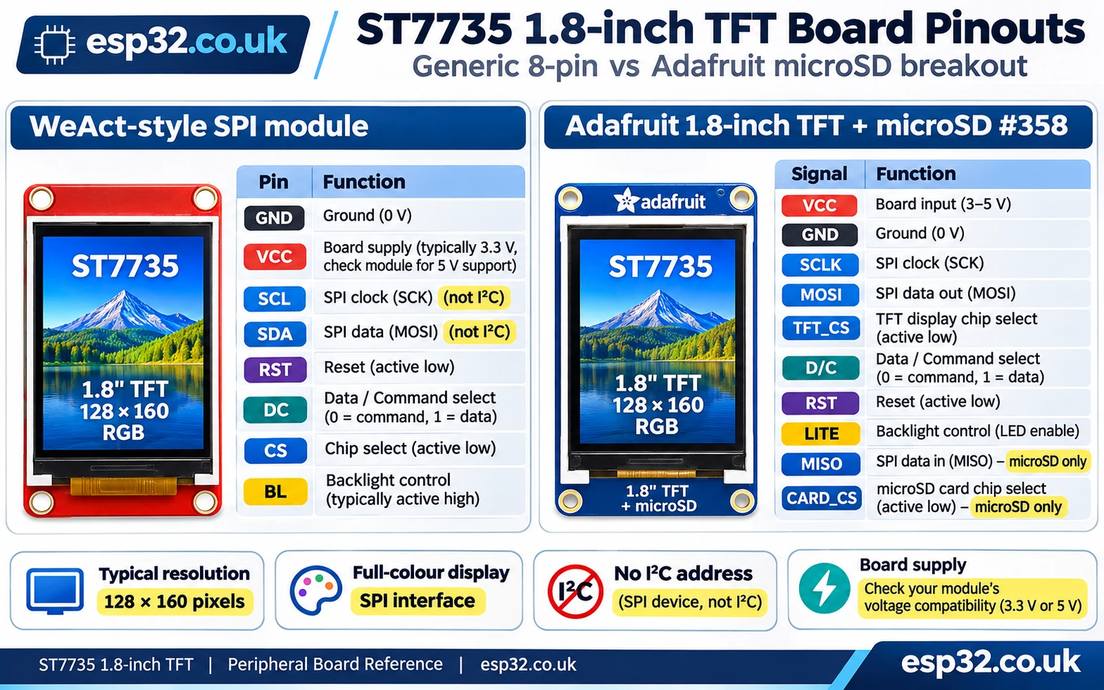
ST7735 display specifications and module variants
| Specification | What it means |
|---|---|
| Common panel | 1.8-inch diagonal colour TFT, generally 128 × 160 pixels |
| Controller family | ST7735R or ST7735S; board-specific init table and offsets can differ |
| Colour | Controller supports up to 18-bit pixel formats; RGB565 is the common 16-bit drawing format in Arduino libraries |
| Main interface | Four-wire SPI-style signalling: SCK, MOSI, CS, D/C, plus reset; not an I²C device |
| Typical cheap breakout | Eight labels: GND, VCC, SCL, SDA, RES/RST, DC/A0, CS, BL/LEDPrice |
| Adafruit breakout | 1.8-inch 128×160 TFT with SPI microSD, level shifting/regulator and EYESPI connector on current revisions |
| Power | Adafruit documented breakout accepts 3–5 V at VCC/VIN; generic modules vary, and bare ST7735 is not a 5 V GPIO device |
| Default orientation | Usually 128 pixels across by 160 down, but can rotate through software |
| LCD memory | Internal display RAM in controller; Adafruit GFX does not require a full-screen MCU buffer for simple drawing |
| Full RGB565 frame size | 128 × 160 × 2 = 40,960 bytes, only if an application chooses to hold a full software framebuffer |
| Backlight | Separate LED supply/control path, usually labelled BL, LED or LITE; power design is board-specific |
| Arduino drivers | Adafruit ST7735 and ST7789 Library, plus Adafruit GFX and Adafruit BusIO dependencies |
Adafruit describes its 1.8-inch 128×160 breakout as an ST7735R-based module with a microSD cardAliExpress price slot. The popular WeAct Studio and other inexpensive eight-pin boards may be marked ST7735S. ST7735, ST7735R, ST7735S and ST7789 should not be conflated: they belong to related display-driver families but may require different initialization commands, panel dimensions and colour/offset settings.
Eight-pin ST7735 module pinout: what each label actually means
A documented WeAct Studio 1.8-inch ST7735 board uses the physical header order GND, VCC, SCL, SDA, RST, DC, CS, BL. Many visually similar boards share this sequence, but others reverse or rearrange it, or include additional pins. Always read the silkscreen on the board you actually have before using a connector diagram or plugging in power.
| Common printed label | ST7735 SPI signal | ESP32 example / notes |
|---|---|---|
| GND | Ground | ESP32 GND |
| VCC / VDD | Breakout input supply | ESP32 3V3 if module supports it; 5V support cannot be inferred from other boards |
| SCL / SCK / CLK | SPI clock input (not I²C SCL) | ESP32 GPIO18 |
| SDA / DIN / MOSI | SPI data input (not I²C SDA) | ESP32 GPIO23 |
| RST / RES | Display active-low reset | ESP32 GPIO25 |
| DC / A0 | Data versus command select | ESP32 GPIO26; A0 here is not an analogue ADC channel |
| CS / TFT_CS | SPI chip select, active low | ESP32 GPIO27 |
| BL / LED / LITE | LCD LED backlight control/supply | Follow PCB specifications; use fixed supply only if documented as safe |
The display is a write-only SPI peripheral in this standard eight-pin arrangement: the controller accepts data on MOSI but does not expose a return-data MISO connection on this module. Consequently, an Arduino I²C scanner will never find a typical ST7735 TFT. Searching for a display address such as 0x3C is a category error: that address applies to many SSD1306/SH1106 OLED modules, not ST7735 SPI screens.
Adafruit 1.8-inch ST7735 breakout signals with microSD
The Adafruit 1.8-inch SPI TFT breakout has a richer set of documented signals. Its EYESPI connector provides the control and microSD interface without needing to reproduce an undocumented through-hole sequence. The main functions are: VCC/VIN, GND, SCLK, MOSI, TFT_CS, D/C, RST, LITE, and, for microSD, MISO and CARD_CS. The MISO belongs to the SD-card SPI interface; the TFT itself is essentially write-only.
| Adafruit breakout label | Purpose |
|---|---|
| VCC/VIN | Breakout supply; Adafruit documents 3–5 V input, including its own regulator and level shifting |
| GND | Common ground |
| SCLK / SCK | Shared SPI clock for TFT and SD |
| MOSI | Shared SPI data into TFT/SD |
| TFT_CS / TCS | Display chip-select; held low only while TFT is being addressed |
| D/C | Display command/data select |
| RST | Display reset |
| LITE | Backlight PWM/enable input, with board-specific default pull-up behaviour |
| MISO | Data from microSD to microcontroller; not required for TFT-only drawing |
| CARD_CS / SDCS | Independent microSD chip-select |
| EYESPI 18-pin FPC | Optional connector for the breakout signals, not an I²C STEMMA QT interface |
Board identity matters. Adafruit’s breakout protection circuitry should not be assumed present on an eight-pin generic panel. Conversely, a cheap board with a separate VCC regulator is not automatically safe for 5 V SPI input levels. On a classic 3.3 V ESP32, power and drive a known 3.3 V-compatible module at 3.3 V.
Why do SCL and SDA on an ST7735 mean SPI rather than I²C?
Vendors reuse the labels SCL and SDA to mean serial clock and serial data even on SPI-only display controllers. On a typical eight-pin ST7735, the extra CS and DC inputs are the clues: an SPI transaction uses the chip-select line and a separate command/data selection line. A four-pin I²C OLED has neither of these exposed in the same way.
| Printed TFT label | Actual ST7735 meaning | Compare to I²C OLED |
|---|---|---|
| SCL | SPI SCLK / SCK, connect to ESP32 hardware SPI clock | Not an I²C bus clock in this configuration |
| SDA | SPI MOSI (master output to TFT data input) | Not bidirectional I²C SDA |
| CS | SPI chip select for this device | Not an I²C address selector |
| DC / A0 | Selects whether bytes represent display commands or pixel data | Not an ESP32 analogue pin |
| RST | Hardware reset | Different from an I²C address jumper |
| BL | Backlight control/power | No equivalent signal on a typical monochrome OLED |
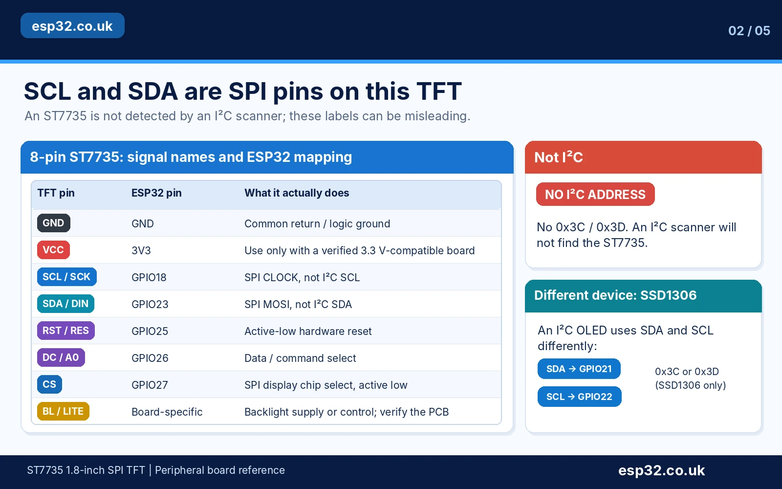
There is normally no I²C address or address solder-jumper setting to discuss for an eight-pin ST7735. If you need two displays on the same SPI bus, they can share SCK and MOSI but should use separate CS signals, with DC/RST requirements implemented for the actual boards.
Power and backlight: VCC is not always the same as BL
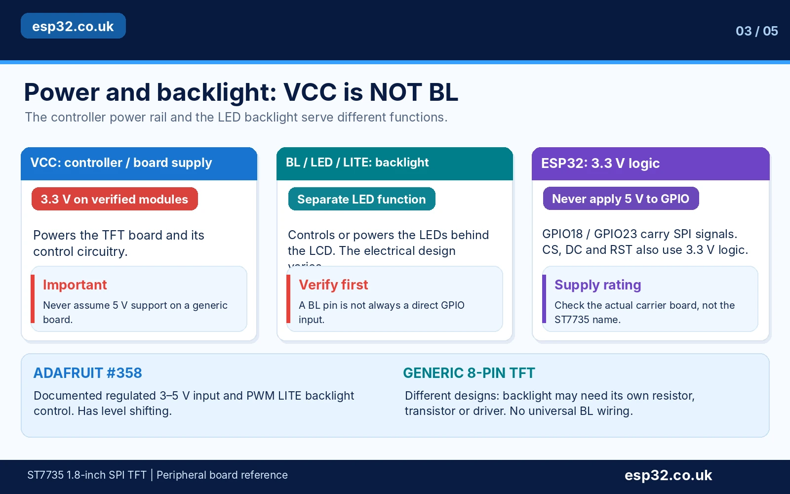
A TFT liquid-crystal panel needs a backlight to be visible in ordinary conditions. Many eight-pin boards expose BL separately from VCC. Some BL pins go through an onboard transistor or resistor so a logic-level PWM signal works; others connect more directly to the LED anode or supply. There is no safe universal ESP32 GPIO-to-BL connection without knowing the current and circuitry of that exact breakout.
| Electrical question | Correct approach |
|---|---|
| What powers the display electronics? | The module input labelled VCC/VIN, at the voltage specified for that module |
| What turns on the LEDs? | The separate BL/LED/LITE circuit on modules exposing one, or internal board circuitry |
| Can ESP32 GPIO drive BL directly? | Only if the vendor documents a low-current logic/PWM input with compatible voltage and current |
| Can I connect BL to 3V3? | Only on modules whose documentation says the BL pin is a voltage-compatible backlight enable/supply input |
| Can I use PWM dimming? | Yes with documented onboard driver, or with an external suitable transistor/MOSFET and LED current limiting |
| Is VCC=5 V universally okay? | No. Adafruit/WeAct documented examples support it; many generic carriers or bare panels do not |
| Are ST7735 GPIO pins 5 V tolerant? | Do not assume so; use 3.3 V logic or an appropriately documented level shifter |
For Adafruit’s 1.8-inch EYESPI breakout, LITE is documented as a PWM backlight input that can be driven or pulled low, and its power input is specified for 3–5 V. That behaviour is a verified board feature. A bare ST7735 display or an unknown board may instead require an LED current-limited drive circuit.
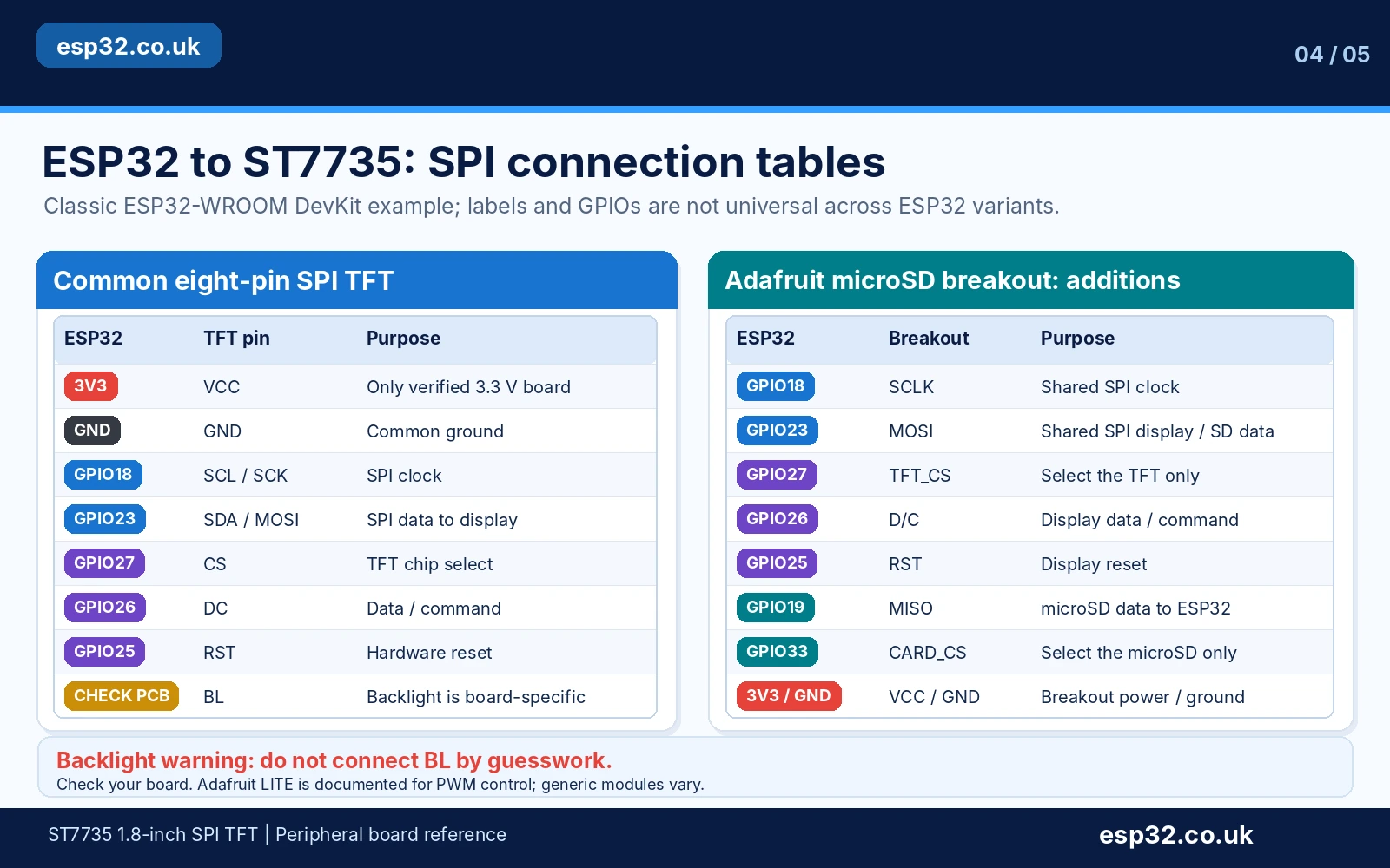
ESP32-to-ST7735 SPI connection table
The first example is for a classic ESP32-WROOM-32 DevKit and the common eight-pin 3.3 V SPI TFT. The chosen CS/DC/RST GPIOs, 27/26/25, are ordinary output choices for this example; the hardware SPI signals use GPIO18 SCK and GPIO23 MOSI. The module must have a compatible supply and its backlight must be connected as documented for its specific PCB.
| Classic ESP32 pin | Generic eight-pin ST7735 label | Purpose |
|---|---|---|
| 3V3 | VCC | 3.3 V module supply, if rated for it |
| GND | GND | Shared reference |
| GPIO18 | SCL / CLK / SCK | Hardware SPI clock |
| GPIO23 | SDA / DIN / MOSI | Hardware SPI master-out data |
| GPIO27 | CS | Active-low TFT chip select |
| GPIO26 | DC / A0 | Selects command or data |
| GPIO25 | RST / RES | Active-low display reset |
| Board-specific; not automatically a GPIO | BL / LED | Backlight control/power; verify rating before connecting |
| Not required for TFT-only | MISO | Eight-pin display normally has no read-back data pin |
On ESP32-C3, C6, S3 and other boards the appropriate GPIOs and SPI controllers differ. Use the actual board’s pinout and configure SPI.begin(SCK, MISO, MOSI, SS) with the values you selected. Never copy an ESP32-WROOM pin diagram onto an XIAO ESP32-C6 just because both have “ESP32” in the name.
Optional Adafruit breakout microSD wiring
If the actual Adafruit microSD breakout is fitted, share SCK/MOSI between display and card, then provide a separate SD chip-select and card-data MISO input. The TFT and SD must not both be selected at once. The additional connections below are only for a breakout with the microSD holder and exposed SD SPI signals, not the generic eight-pin TFT.
| ESP32 pin | Adafruit ST7735 breakout signal | Meaning |
|---|---|---|
| GPIO18 | SCLK | Shared SPI clock |
| GPIO23 | MOSI | Shared SPI output into TFT and SD |
| GPIO19 | MISO | SD card read-back to ESP32 |
| GPIO27 | TFT_CS | Select TFT when drawing |
| GPIO33 (example) | CARD_CS / SDCS | Select microSD when accessing card |
| GPIO26 | D/C | TFT data/command |
| GPIO25 | RST | TFT reset |
| 3V3, GND | VCC/VIN, GND | Breakout supply/return |
| As documented for board | LITE | Backlight brightness/enable |
Arduino IDE: working ST7735 128×160 colour graphics example
Install Adafruit ST7735 and ST7789 Library and Adafruit GFX Library using Library Manager; accept the prompted Adafruit BusIO dependency. Select your classic ESP32 board and serial port. This example targets a common 1.8-inch 128×160 ST7735 module and starts with Adafruit’s frequently used INITR_BLACKTAB init sequence. Some panels need a different tab/offset setting, described below.
#include <Arduino.h>
#include <SPI.h>
#include <Adafruit_GFX.h>
#include <Adafruit_ST7735.h>

// Pin example: classic ESP32-WROOM-32 DevKit.
constexpr int TFT_SCK  = 18;
constexpr int TFT_MISO = 19;  // No connection for 8-pin TFT.
constexpr int TFT_MOSI = 23;
constexpr int TFT_CS   = 27;
constexpr int TFT_DC   = 26;
constexpr int TFT_RST  = 25;

Adafruit_ST7735 tft(TFT_CS, TFT_DC, TFT_RST);

void setup() {
  Serial.begin(115200);
  SPI.begin(TFT_SCK, TFT_MISO, TFT_MOSI, TFT_CS);

  // Common starting point for 1.8" 128x160 modules.
  // If colours or origin are wrong, see tab settings below.
  tft.initR(INITR_BLACKTAB);
  tft.setRotation(0);
  tft.fillScreen(ST77XX_BLACK);

  tft.drawRect(0, 0, tft.width(), tft.height(), ST77XX_WHITE);
  tft.setTextWrap(false);
  tft.setTextSize(1);
  tft.setTextColor(ST77XX_CYAN);
  tft.setCursor(8, 9);
  tft.print("esp32.co.uk/");

  tft.drawFastHLine(8, 24, 112, ST77XX_YELLOW);
  Serial.println("ST7735 ready");
}

void loop() {
  static unsigned count = 0;
  tft.fillRect(8, 43, 112, 42, ST77XX_BLACK);
  tft.setCursor(8, 43);
  tft.setTextColor(ST77XX_GREEN);
  tft.setTextSize(1);
  tft.print("Uptime:");
  tft.setCursor(8, 59);
  tft.print(millis() / 1000);
  tft.print(" sec");
  tft.drawRect(8, 90, 112, 14, ST77XX_WHITE);
  tft.fillRect(10, 92, count % 109, 10, ST77XX_BLUE);
  tft.fillRect(10 + (count % 109), 92, 109 - (count % 109),
               10, ST77XX_BLACK);
  count += 5;
  delay(500);
}
The example deliberately has no made-up backlight GPIO operation. For a board that requires BL/LED enable, supply that pin using the manufacturer’s documented method before testing. Adafruit’s hardware-SPI Adafruit_ST7735(cs, dc, rst) constructor, initR(), setRotation() and Adafruit GFX drawing calls are part of the published library API. This sketch has not been physically bench-tested on your particular module.
How to choose BLACKTAB, GREENTAB or a different panel initialiser
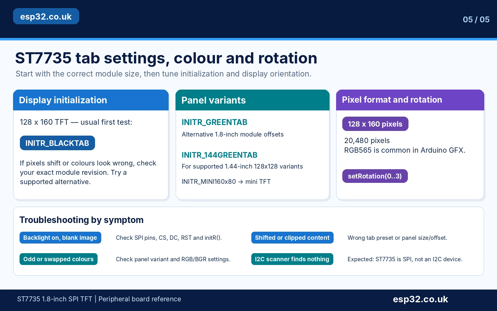
A blank screen with a working backlight can reflect an initialization mismatch, but so can a power, chip-select or SPI fault. Adafruit’s library provides multiple init sequences for different panel families. Use INITR_BLACKTAB as a starting point for many 1.8-inch displays. Some 1.8-inch green-tab/offset designs use INITR_GREENTAB. The 1.44-inch panels may use INITR_144GREENTAB, while narrow 80×160 mini displays can require INITR_MINI160x80. Their physical sizes and memory offsets are not interchangeable.
| Panel or symptom | Library setting to consider | Caution |
|---|---|---|
| Common 1.8-inch 128×160 ST7735 | tft.initR(INITR_BLACKTAB) | Good initial test, not universal |
| 1.8-inch with green-tab-type origin offset | tft.initR(INITR_GREENTAB) | Check vendor specification and actual alignment |
| 1.44-inch 128×128 | tft.initR(INITR_144GREENTAB) | Different geometry; do not use on 128×160 without reason |
| 0.96-inch 80×160 | tft.initR(INITR_MINI160x80) | Different offsets and shape |
| Wrong RGB/BGR colour order | Try supported colour order or init variant | Do not assume a red tab on one maker means the same thing on all |
| Drawing is clipped after rotation | Check setRotation() and panel offset | width() and height() can swap at rotations 1 and 3 |
Rotation, colours and graphics buffering
A 128×160 panel has 20,480 visible pixels. At 16-bit RGB565, a complete copied frame in ESP32 RAM would occupy 40,960 bytes, but the normal Adafruit GFX + ST7735 drawing API does not allocate that full screen buffer by default. It sends drawing operations through SPI to the controller’s own graphics RAM. This matters if you compare an LCD TFT to a monochrome SSD1306 OLED, whose Adafruit driver generally does use a full one-bit MCU buffer.
Calling tft.setRotation(0), 1, 2 or 3 changes orientation; the resulting visible dimensions can be queried with tft.width() and tft.height(). If your display looks rotated, mirrored or has misplaced margins, check its supported tab variant before blaming the SPI pin connections.
Where screen refresh is visibly slow, prefer updating only the changed values instead of filling and redrawing the entire panel continuously. On a busy SPI bus that also carries a microSD card, ensure the card and display libraries each manage their own CS pin and compatible transactions. Higher SPI clock speeds are not automatically better with thin jumper leads or marginal breakout level shifting.
ST7735 black screen, wrong colours or white backlight: troubleshooting
| Problem | Likely cause and action |
|---|---|
| Backlight off and no pixels | Power/ground error or BL not driven per documented module requirement; verify supply before testing code |
| Backlight on but solid white screen | Display controller not initialized; check CS, DC, RST, SPI SCK/MOSI, board voltage and selected init table |
| Only part of graphics visible | 128×160 versus 128×128/80×160 geometry mismatch, tab offset or rotation |
| Red and blue swapped | RGB/BGR order setting or panel init variant; verify using a solid red/green/blue test |
| Mirrored or shifted graphics | Panel tab/origin offset differs from the default library setting |
| I²C scanner finds no display | Normal: ST7735 is SPI, so no I²C address exists |
| Screen draws random pixels intermittently | SPI clock too high, unstable supply, poor connector or conflicting chip selects |
| Text is clipped | Use tft.width()/height() after setRotation and check screen dimensions |
| Backlight cannot dim | BL pin may be a raw LED supply, not a logic/PWM input; use a suitable driver |
| Image from microSD fails | Verify separate card CS, MISO connection, filesystem and SPI bus ownership |
| ESP32 reset at startup | Investigate power surges/backlight supply and pin conflicts before changing code |
| No module detected at 0x3C | 0x3C is an SSD1306/SH1106 I²C address, not an ST7735 SPI address |
ST7735 versus SSD1306 OLED, SH1106 and ST7789
The ST7735 is appropriate for inexpensive, compact colour interfaces with icons or graphs. An SSD1306 or SH1106 OLED often needs fewer wires in I²C mode and is suited to small monochrome sensor readouts. An ST7789 TFT is available in higher resolutions such as 240×240, with a related but not interchangeable software and pinout setup. The choice depends on screen area, colour, readability, power, PCB complexity and the bus already used by the project.
| Controller | Common resolution | Interface and practical distinction |
|---|---|---|
| ST7735 TFT | 128×160; also 128×128 and 80×160 variants | Colour SPI; DC/CS control and separate backlight |
| SSD1306 OLED | 128×64 or 128×32 | Usually monochrome I²C on four-pin module; no LED backlight |
| SH1106 OLED | 128×64 visible with 132 controller RAM columns | Usually I²C or SPI; SSD1306 library not always appropriate |
| ST7789 TFT | 240×240 and other panel sizes | Colour SPI; typically different init and panel-offset settings |
If you are comparing OLED options rather than building a TFT project, the related esp32.co.uk/ peripheral articles **#023 SSD1306** and **#024 SH1106** explain their addresses and driver differences. Those articles should only be linked directly once published. For general SPI concepts on another platform, see the existing esp32.co.uk/ STM32 SPI guide.
Frequently asked questions
Does the ST7735 use I²C or SPI?
A standard eight-pin ST7735 TFT uses SPI. Pins called SCL and SDA are respectively clock and data inputs in that module’s serial interface, not an I²C bus pair. There is no I²C slave address to scan.
What is the ESP32 ST7735 pinout?
For the classic ESP32 example in this guide: SCK GPIO18, MOSI GPIO23, CS GPIO27, DC GPIO26 and reset GPIO25, plus correct VCC/GND and board-specific backlight. These are sample GPIO choices rather than a fixed silicon pinout across all ESP32 boards.
Is ST7735 SDA connected to ESP32 GPIO21?
Not in this hardware SPI example. The TFT’s SDA means SPI data-in, which uses ESP32 MOSI GPIO23 on the common classic ESP32 controller. The ESP32 GPIO21/22 pair often used for I²C OLEDs is not directly interchangeable.
Can I connect an eight-pin ST7735 to 5 V?
Only if the specific breakout documentation confirms both its supply input voltage and its input-logic compatibility. Some Adafruit and WeAct modules support 5 V VCC; a bare ST7735 chip or another generic board may not. With ESP32, a known 3.3 V-compatible module is the simplest starting point.
Does the ST7735 need a full 40 KB graphics buffer on ESP32?
No. A full RGB565 copy of 128×160 pixels would occupy 40,960 bytes, but Adafruit GFX can draw directly via the ST7735 driver without allocating that entire buffer in ESP32 RAM. Applications may choose additional buffers for animation.
Why is my display white while serial prints ST7735 ready?
That message only confirms the MCU reached the end of setup. It does not verify the SPI hardware link. Check TFT power and BL separately, then CS/DC/RST, SCK/MOSI, and the correct init table for your panel. The standard eight-pin display cannot acknowledge over I²C.
Can I put an SD card and ST7735 on the same ESP32 SPI bus?
Yes, if the board actually has a microSD slot and separate Card CS signal. SCK and MOSI are shared, MISO returns SD data and each device has a separate active-low CS line. Avoid simultaneous chip selection.
References and source documentation
- Adafruit 1.8-inch TFT breakout pinouts — confirmed SCLK/MOSI, TFT CS, D/C, reset, LITE, microSD MISO/Card CS and power behaviour.
- Adafruit ST7735 breakout wiring/testing — hardware-SPI API and first display test.
- Adafruit ST7735 graphics documentation — Adafruit ST7735 and GFX installation.
- Official Adafruit ST7735 graphicstest — current class constructor and panel-tab initializers.
- Adafruit ST7735 and ST7789 Arduino library — library source code.
- WeAct Studio 1.8-inch ST7735 board reference — documented eight-pin header, supply range and backlight control.
- esp32.co.uk/ STM32 SPI reference — related SPI concepts and bus operation.
Editorial scope: This esp32.co.uk/ guide separates documented Adafruit and WeAct Studio hardware from unverified generic clones. The published pin mappings and library calls have been reviewed against source documentation, but have not been bench-tested with every ST7735 panel. All requested accompanying images must show wire-free pinouts and signal tables, with visible esp32.co.uk/ attribution. The image source URLs are placeholders until the exact WebP filenames have been uploaded to the WordPress Media Library.