The STM32 Black PillAliExpress price and ESP32-S3AliExpress price are both compact microcontroller development platforms, and both can run useful firmware without an operating system. Yet choosing between them on processor MHz or the price of a bare board is a poor way to design a product. The Black PillAliExpress price is usually built around an STM32F401 or STM32F411 Arm Cortex-M4 microcontroller. The ESP32-S3 uses a dual-core Xtensa LX7 with integrated 2.4 GHz Wi-Fi and Bluetooth Low Energy (BLE), and is commonly sold inside a module with external flash and, on some variants, PSRAM.
Quick verdict: Choose the STM32F411 Black Pill for a compact, relatively simple control application when you value STM32 HAL, predictable peripheral timing, SWD debugging and established Arm workflows. Choose an ESP32-S3 development board when Wi-Fi, BLE, USB device projects, camera/display work, software ecosystem, larger memory or networking dominate the specification. If your design requires native classical CAN, the ESP32-S3’s TWAI controller provides a path with an external CAN transceiver; the STM32F401 and F411 have no CAN controller. Neither chip has native CAN FD.
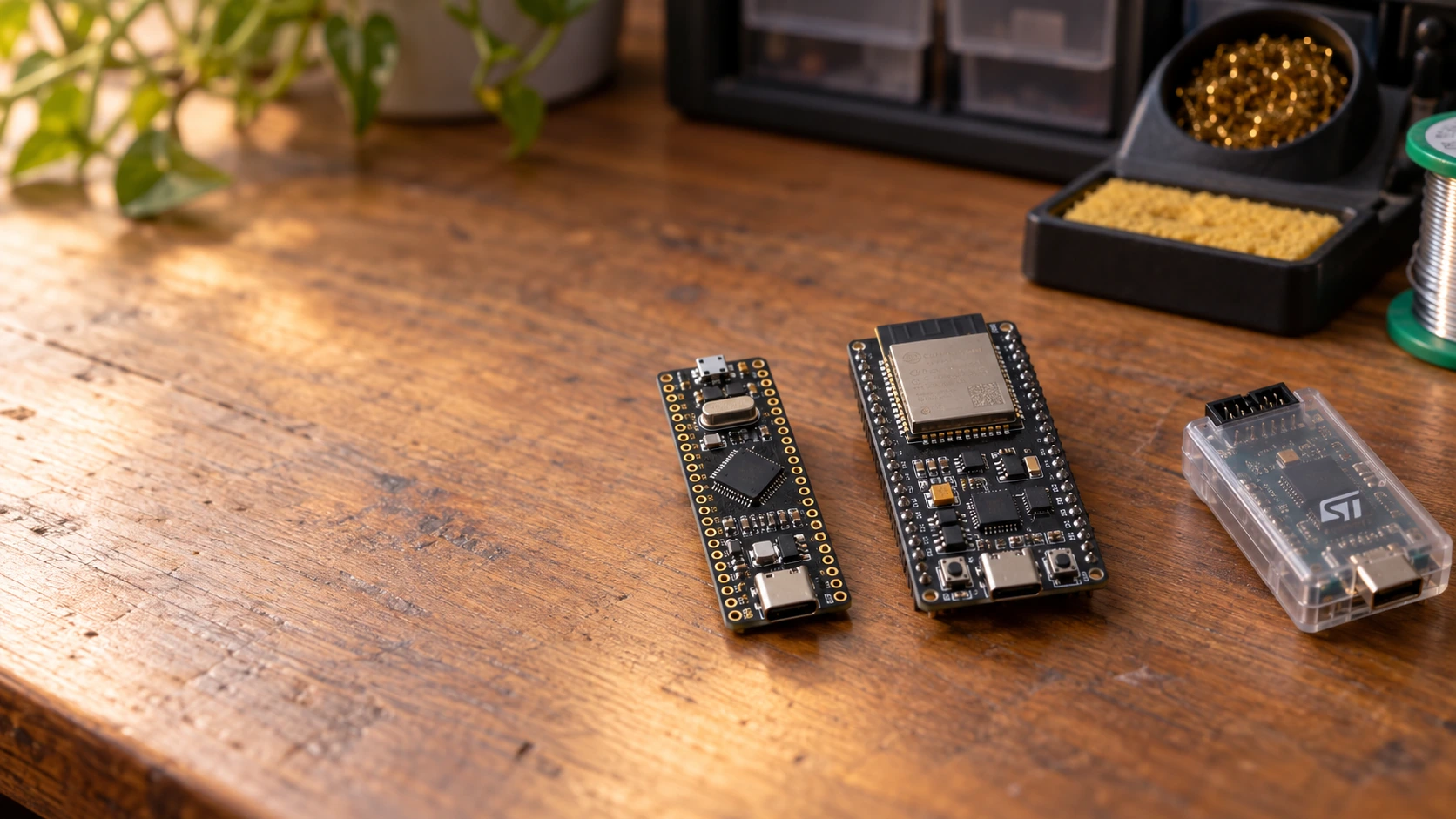
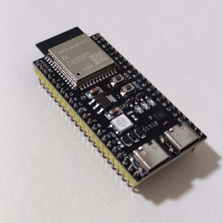
This guide compares real parts, not just labels: STM32F401CCU6, STM32F401CEU6 and STM32F411CEU6 on typical WeAct-style Black Pill boards, against an ESP32-S3-WROOM-1 based development board such as an official DevKitC-1. Exact connector pins, LEDs, memory, oscillator and power circuitry vary with the board revision. Those board details matter as much as the silicon.
Black Pill vs ESP32-S3 specifications at a glance
| Specification | STM32F401 Black Pill | STM32F411 Black Pill | ESP32-S3 module development board |
|---|---|---|---|
| Processor | 1× Arm Cortex-M4 with FPU/DSP | 1× Arm Cortex-M4 with FPU/DSP | 2× Xtensa LX7 with FPU and vector instructions |
| Maximum CPU frequency | 84 MHz | 100 MHz | 240 MHz per core |
| Internal flash / module flash | F401CC 256 KB; F401CE 512 KB internal | F411CE 512 KB internal | External flash on module/board; variant dependent, commonly 8 or 16 MB |
| On-chip SRAM | F401CC 64 KB; F401CE 96 KB | 128 KB | 512 KB SRAM plus other small on-chip memory regions |
| External PSRAM | Not normally fitted; external memory is a separate design task | Same | Available on selected N8R8, N16R8 and other module variants; not universal |
| Radio | None | None | 2.4 GHz 802.11 b/g/n Wi-Fi plus Bluetooth 5 LE; no Bluetooth Classic |
| USB | Full-speed OTG-capable controller; exact board and boot configuration matter | Full-speed OTG-capable controller | Full-speed USB OTG and separate USB Serial/JTAG controller sharing internal-PHY resources |
| CAN | No on-chip CAN | No on-chip CAN | Classical CAN-compatible TWAI controller; external transceiver required |
| CAN FD | No | No | No native CAN FD controller |
| ADC | 12-bit ADC, input count depends on package | 12-bit ADC, input count depends on package | Two SAR ADC units; Wi-Fi interaction makes ADC1 the safer choice for connected applications |
| GPIO logic | 3.3 V design; some individual pads are 5 V tolerant under datasheet conditions | Same | 3.3 V GPIO; do not connect 5 V signals directly |
| Debugging | SWD via ST-LINK or compatible probe | SWD via ST-LINK or compatible probe | USB Serial/JTAG and external JTAG options; depends on board and firmware |
| Main toolchain | STM32CubeMX, CubeIDE, STM32CubeProgrammer; STM32duino optional | Same | ESP-IDF, Arduino-ESP32, PlatformIO, ESPHome and other frameworks |
| Best broad fit | Simple compact F4 control | Compact DSP/control/USB | Connected sensors, dashboards, USB, audio/display and networked automation |
Do not compare MHz as a benchmark. Different instruction sets, clock trees, memory wait states, DMA engines, cache behavior and wireless stacks change real throughput. Equally, the S3’s larger external flash is not the same as having all that memory available as fast on-chip RAM.
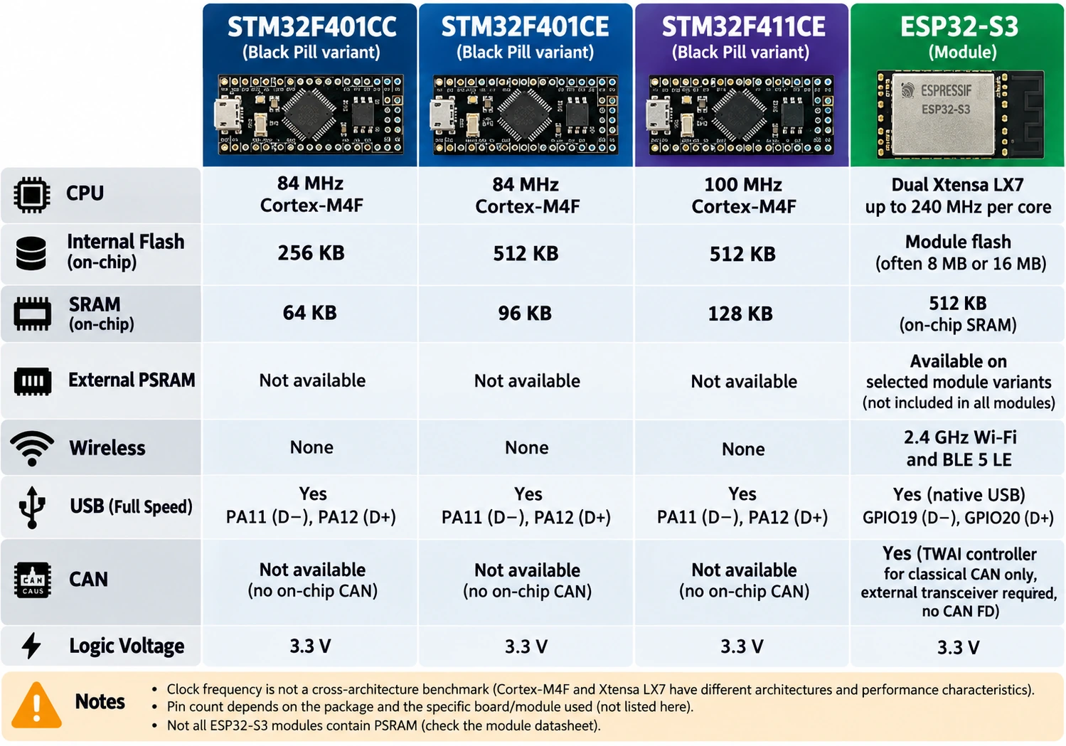
Check the actual chip marking before buying
“Black Pill” describes a shape and community board style, not a controlled STM32 product number. A seller may offer an F401CC board, an F401CE board or an F411CE board using near-identical photographs. F401CC gives 256 KB flash and 64 KB SRAM, whereas F401CE has 512 KB flash and 96 KB SRAM. F411CE increases the maximum CPU clock to 100 MHz and provides 128 KB SRAM. Those differences influence firmware size, USB buffer headroom, logging, RTOS tasks and graphics.
Our existing STM32F401 vs STM32F411 Black Pill comparison explains that distinction in greater detail. For physical wiring, also see the STM32F411CE Black Pill pinout and Arduino guide. A PCB color or retail title should never override the MCU’s marking or the manufacturer’s schematic.
ESP32-S3 names require the same discipline. ESP32-S3 describes a silicon family. ESP32-S3-WROOM-1-N8R8 identifies a particular module memory combination. ESP32-S3-DevKitC-1 identifies a development board carrying a module and other circuitry. N8R8 commonly denotes 8 MB flash plus 8 MB PSRAM; an N8 without the R8 suffix does not promise PSRAM. Some module families use different flash and memory arrangements. Do not configure a project for PSRAM until you’ve identified and verified what is fitted.
CPU performance: Arm Cortex-M4 versus dual Xtensa LX7
A Black Pill with F411CE offers a single Cortex-M4 at up to 100 MHz with hardware single-precision floating point and DSP instructions. Its appeal is that the microcontroller performs one main set of tasks without an integrated Wi-Fi stack competing for processor time and memory. Timer interrupts, DMA transfers and control algorithms can be analysed directly. It is a good environment for learning interrupt timing, writing firmware with explicit resource ownership and debugging repeatable execution paths.
ESP32-S3 uses two Xtensa LX7 cores at up to 240 MHz. Its FreeRTOS-based software environment allows application, protocol and service tasks to be scheduled across a more complex system. Its vector extensions are useful for certain audio, signal processing and small machine-learning workloads. An ESP32-S3 may finish some general computations faster, but this cannot be inferred from a simplistic 240 ÷ 100 calculation. Shared memory, cache misses, task wake-ups and Wi-Fi activity matter.
A useful project test is to build the same algorithm twice: use equivalent integer or floating-point types, identical input data and optimizations, then measure elapsed time, worst-case latency and RAM consumption. That gives much more defensible evidence than selecting a board from a synthetic headline score.
Deterministic timing versus overall processing capacity
Suppose a motor or power-converter controller must sample a signal and update PWM at a guaranteed interval. A dedicated STM32 timer can trigger ADC events and generate outputs without relying on high-level application code to toggle GPIO at the exact moment. That is a strong reason to retain an STM32 design even when a competing wireless MCU has higher CPU frequency.
The ESP32-S3 also contains capable hardware timers, PWM engines, DMA and dedicated motor-control PWM resources; it is not limited to unreliable software timing. The correct distinction is which exact hardware peripheral and driver provide the timing contract and how radio/network activity is isolated. Never state that an ESP32-S3 is unsuitable for all real-time control, or that every STM32 implementation is automatically deterministic. Verify the timer features, synchronization, interrupts and worst-case latencies that matter to your system.
Memory: internal SRAM, external flash and PSRAM
Memory comparisons often make the ESP32-S3 look dramatically stronger, with good reason: 512 KB of on-chip SRAM and module options with megabytes of flash and PSRAM are genuinely helpful. But the different memory classes serve different purposes. Executable code and constant resources are usually stored in external flash on an S3 module, backed by the chip’s cache; PSRAM can hold larger data structures, frame buffers and selected allocations, but it has accessibility and performance constraints relative to internal RAM.
On an STM32F411CE, 128 KB SRAM and 512 KB internal flash can support a surprisingly substantial sensor controller, USB device, instrument UI or DSP pipeline if buffers are deliberately sized. Even the F401CC’s 64 KB SRAM is enough for many periodic measurements and fixed-memory state machines. Conversely, a Wi-Fi server with JSON, TLS, image buffers and logging can make such capacities awkward or insufficient.
Before choosing, estimate the memory budget: application code size, bootloader and update space, stack for each task or interrupt context, communication buffers, queue sizes, file systems, DMA working areas and worst-case concurrent network activity. For an S3, reserve internal-memory headroom for drivers and time-critical buffers even when PSRAM is fitted. For a Black Pill, consider whether firmware upgrades require a second image or whether updates are performed through SWD/DFU without dual-bank application storage.
Example: 320 × 240 display frame buffer
A full RGB565 frame uses 320 × 240 × 2 = 153,600 bytes, roughly 150 KiB before graphics library metadata or a second buffer. That exceeds the total RAM on an F411CE, so a full buffered approach would need a different design: tiles, line buffers, external RAM or a different MCU. A PSRAM-equipped ESP32-S3 can handle much larger display buffers, though drawing speed and DMA requirements still depend on the display bus and memory allocation.
The lesson is not that STM32 cannot drive a display. It can. The correct question is whether the intended graphics pipeline needs a full frame buffer or only small scanline and widget buffers.
Wireless connectivity is the largest difference
A typical STM32F401/F411 Black Pill has no integrated Wi-Fi, BLE or radio antenna. It can communicate with a wireless module over UART, SPI or another bus, but that adds hardware, firmware, power budget and integration steps. A Black Pill connected to an external ESP32 or radio module may still be a sensible design when a dedicated controller must remain separate from network-facing software.
ESP32-S3 integrates 2.4 GHz Wi-Fi and Bluetooth 5 Low Energy. It can host a local HTTP API, publish MQTT data, support provisioning and communicate with common home-automation software using supported firmware. The S3 does not provide 5 GHz Wi-Fi or Bluetooth Classic. If a feature needs Bluetooth Classic SPP, check a different ESP32 model rather than assuming every chip sold as ESP32 supports the same radio modes.
For Home Assistant or a remote sensor gateway, built-in wireless usually makes the S3 more practical and less costly to integrate. For an isolated measurement circuit inside a sealed instrument, the integrated radio may add little value. Remember also that Wi-Fi bursts increase instantaneous current and demand a competent 3.3 V supply, proper decoupling and suitable antenna placement.
USB: the Black Pill and ESP32-S3 solve different problems
Both families support full-speed USB hardware, but the connector and firmware path are critical. On common Black Pill boards, the STM32’s USB D− and D+ typically use PA11 and PA12. Depending on the exact MCU and bootloader support, a suitable USB DFU factory boot mode may be available; confirm the specific device in ST application note AN2606 rather than copying F103 Blue Pill instructions. For reliable programming and full interactive debugging, SWD via an external ST-LINK is still a good default.
ESP32-S3 provides both a dedicated USB Serial/JTAG controller and a USB OTG full-speed peripheral. The built-in USB Serial/JTAG interface can expose a serial port and debug connection over a suitable data cable and port, often without an external UART adapter. The USB OTG peripheral supports other classes through appropriate firmware and PHY configuration. Do not claim these are two independent USB PHYs: the internal PHY is shared/routed according to hardware and configuration. Likewise, Espressif’s USB DFU instructions describe important limitations; DFU through the OTG controller is not the same as ordinary USB Serial/JTAG flashing.
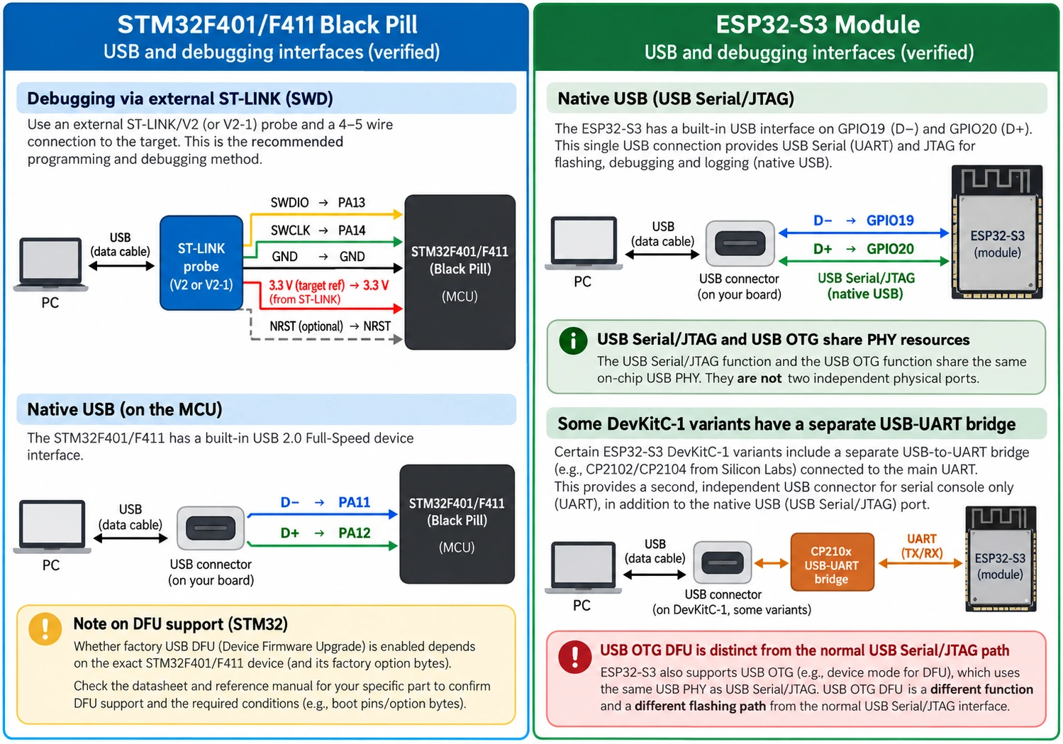
Practical upload paths
| Task | STM32 F401/F411 Black Pill | ESP32-S3 development board |
|---|---|---|
| First firmware upload | ST-LINK over SWD is robust; USB DFU only where correctly supported and wired | Native USB Serial/JTAG or USB-to-UART path according to the board |
| Source-level debugging | SWD pins PA13/PA14 with an external probe | Native USB JTAG may be available; verify board and software configuration |
| USB serial to PC | CDC user firmware over target USB, or external UART adapter | USB Serial/JTAG CDC, USB CDC firmware or USB-to-UART converter depending on design |
| Custom USB device | USB FS firmware stack on the STM32 | USB OTG device stack, with correct PHY/mode and firmware |
| Recovery from broken application | Connect under reset by SWD; inspect BOOT0 and NRST | BOOT/GPIO0 download mode, reset, serial/USB flashing, ROM recovery where allowed |
Do not rely on a charging-only USB cable. A lit power LED proves power, not enumeration. On an S3 DevKitC-1, some revisions have two different USB connectors: one for a USB-to-UART bridge and another for the MCU’s native USB. Identify the physical connector from the exact board user guide.
GPIO, ADC and sensor interfacing
Both platforms generally operate using 3.3 V logic. That does not make their pins interchangeable or universally 5 V tolerant. On selected STM32F4 pins, datasheets specify FT conditions for digital inputs, but that is pin- and operating-mode-dependent and does not apply to arbitrary ADC or unpowered-pin situations. ESP32-S3 GPIO must not be driven with 5 V; use proper level shifting for 5 V logic and voltage conditioning for analog sensors.
For basic I²C sensors, either board can work well. A BME280 typically needs 3.3 V-compatible I²C wiring, a common ground and pull-up resistors to the permitted logic supply. On the S3, I²C functions can be assigned through the GPIO matrix; example pins in one tutorial are not universal hardware defaults. On the Black Pill, pin assignment follows the MCU alternate-function matrix and, for Arduino examples, the selected core’s variant definition.
For analog measurements, the F401/F411 exposes a 12-bit ADC; the exact accessible channels depend on the package and wiring. ESP32-S3 has two SAR ADC units, but ADC2 may conflict with Wi-Fi operation, and its continuous-mode ADC2 DMA support is limited. For a Wi-Fi-connected analog sensor, prefer an appropriate ADC1 pin on the S3, then use calibration and characterization if precision matters. For demanding measurement accuracy, either board may benefit from an external ADC with a proper voltage reference and front end.
Pins that should not be treated as general free GPIO
On a Black Pill, reserve PA13/PA14 when SWD debugging is needed and PA11/PA12 for native USB. A common PC13 LED or PA0 button may be wired differently on clone boards. Some board variants connect an external SPI flash device to signals that appear free in an MCU pin list. Consult the PCB revision.
On an ESP32-S3, GPIO0 and other strapping pins require careful boot-state design. GPIO19/20 commonly serve USB D−/D+, and pins used by the module’s flash or octal PSRAM are not free for unrelated external wiring. The exact RGB LED GPIO also changes between official DevKitC-1 revisions. The S3 silicon’s advertised 45 programmable GPIOs does not mean all 45 are exposed and unconstrained on a WROOM development board.
CAN bus: an easily missed difference
This is a particularly useful trap to explain because our site already has separate CAN-focused tutorials. The STM32F401 and STM32F411 have no internal bxCAN controller. Adding only a TJA1050, SN65HVD230 or similar physical transceiver does not create controller functionality. You would need an external CAN controller on SPI (plus a transceiver), or you should select another STM32 containing CAN/FDCAN, such as an appropriately specified G4 device.
The ESP32-S3 includes a TWAI controller compatible with Classical CAN 2.0. That controller produces logic-level TX/RX signals, not the differential physical bus. You still need a correctly powered CAN transceiver, common-mode protection, correct logic levels, CAN_H/CAN_L wiring and proper bus termination. It is not a native CAN FD controller, and a CAN FD-rated transceiver alone does not upgrade classical CAN controller frames to CAN FD.
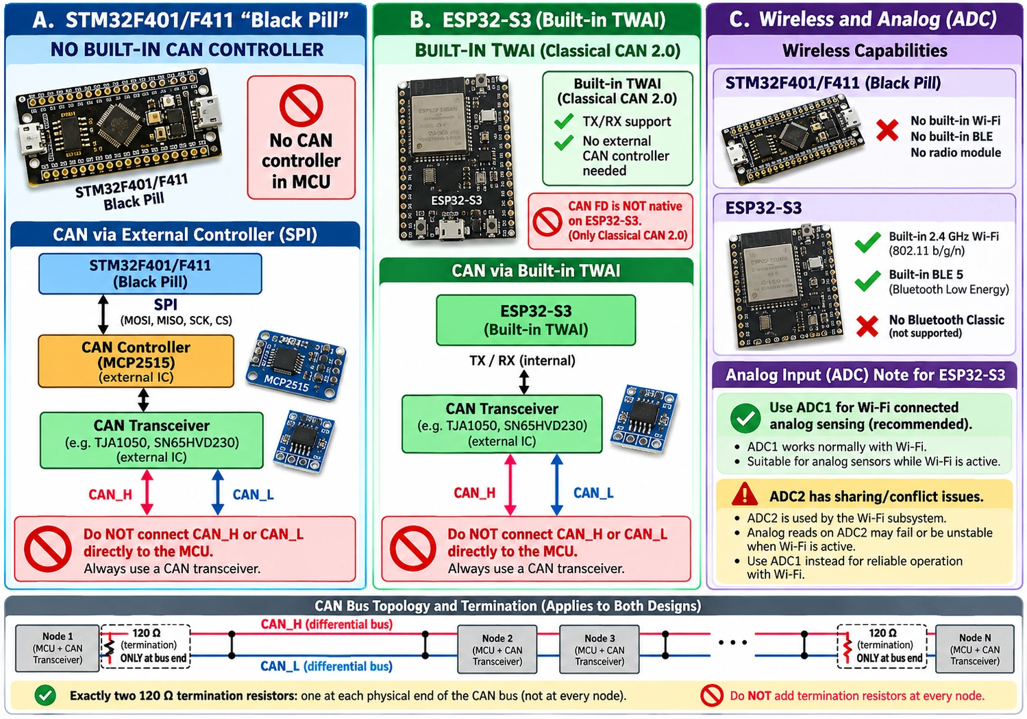
For a simple classic CAN telemetry node connected to Wi-Fi or MQTT, ESP32-S3 plus a suitable transceiver is an appealing single-MCU approach. For a safety-critical automotive control unit, industrially qualified hardware, isolation/EMC design, watchdog architecture and functional-safety processes are much more important than a cheap development board comparison. Choose production hardware and software accordingly.
Timers, PWM, audio and display interfaces
The STM32F4 timer ecosystem is strong for PWM, input capture, encoder reading and synchronized events. A Black Pill may be ideal for pulse measurement, actuator timing, sensor acquisition or firmware that closely controls peripheral registers. The specific timer instance, alternate-function setting and GPIO combination should be verified for F401 or F411 rather than copying pin names from a different STM32 family.
ESP32-S3 includes LED PWM, motor-control PWM, RMT, I²S, LCD/camera-oriented interfaces and DMA resources. These make it attractive for addressable LEDs, audio, microphones, compact displays and camera applications. Yet a microcontroller offering a camera peripheral is not evidence that a generic development board already has a camera connector, sufficient PSRAM or the necessary power supply. Pair the target module with a board designed for your project or wire an appropriate external module.
WS2812 addressable LED example: an S3 can use a dedicated RMT-style driver rather than blocking the CPU to bit-bang each data pulse. An STM32 can produce repeatable patterns using timers and DMA with a suitable waveform implementation. Both approaches can be good; the trade-off lies in library maturity and the required CPU/interrupt budget.
Software development: CubeIDE versus ESP-IDF, Arduino and ESPHome
The Black Pill works naturally with STM32CubeMX for pin/clock configuration, STM32CubeIDE for building and debugging, and STM32CubeProgrammer for device programming. Current CubeIDE 2.x workflows use CubeMX as a separate tool, unlike many older tutorials. HAL is convenient for application development, while LL or direct register work can be used when measured overhead requires it. STM32duino gives another route for Arduino sketches, but it cannot make an absent peripheral available.
ESP32-S3’s native development path is ESP-IDF, with FreeRTOS, networking components and supported USB, GPIO and peripheral drivers. Arduino-ESP32 may be faster for one-off sensor projects; ESPHome is attractive when Home Assistant integration is the principal goal. The code architecture is different: network tasks, event loops, flash partitions and OTA updates demand attention beyond a basic loop.
A productive rule is to choose the board with the toolchain your team can maintain. A professional STM32 control design might gain nothing from adding wireless middleware. Conversely, a DIY Wi-Fi meter may not justify building an independent radio stack and update service just to keep an Arm Cortex-M4 at the center.
Example 1: STM32 Black Pill PC13 LED (HAL)
On many WeAct-style Black Pills, the user LED is connected to PC13 and is active-low, but this must be checked against the actual board. After selecting the right F401/F411 device in CubeMX, configure PC13 as a GPIO output and start from the generated project. The following line belongs inside an application loop when the GPIO and clock have been initialized:
/* Example: assumes PC13 is an output connected to the board LED. */
HAL_GPIO_TogglePin(GPIOC, GPIO_PIN_13);
HAL_Delay(500);
If the LED stays on or off, check whether its drive polarity, board revision and PC13 wiring match the assumptions. Do not change every GPIO register at random. Use the debugger to confirm the code runs, then measure the output pin. Code shown here is an educational example and was not bench-tested on every clone.
Example 2: ESP32-S3 basic LED blink (Arduino)
For a portable first sketch, connect an external LED through an appropriately chosen resistor to a verified, free 3.3 V GPIO, rather than relying on an addressable RGB LED whose pin and driver vary by board revision. For example, if GPIO4 is truly available on your target board:
const int LED_PIN = 4; // Example GPIO: confirm your exact board schematic
void setup() {
  pinMode(LED_PIN, OUTPUT);
}
void loop() {
  digitalWrite(LED_PIN, HIGH);
  delay(500);
  digitalWrite(LED_PIN, LOW);
  delay(500);
}
Use an LED resistor, keep the pin current within the datasheet and do not confuse a 3.3 V GPIO with a board’s 5 V USB supply. The example avoids claiming that all S3 boards ship with a simple GPIO-driven LED.
Power consumption: compare the application, not only the processor
An STM32 running without a radio generally offers a simpler path for budgeting a small always-on controller. But it would be misleading to promise that every Black Pill consumes less power than every ESP32-S3 design: development-board regulators, USB-UART bridges, indicator LEDs, external memories, sensor loads and firmware duty cycle can dominate consumption.
The ESP32-S3 radio draws substantially higher peak current during Wi-Fi operation than a sleeping sensor MCU, so regulators and trace layout need to tolerate transmit bursts. At the same time, an S3 that sleeps most of the time and sends brief packets may have perfectly acceptable battery life in a well-designed system. A Black Pill plus a separate always-on Wi-Fi module can use more total energy and occupy more PCB area than a properly configured S3-only design.
A real comparison needs active current, idle current, deep-sleep current where supported, wake-up latency, wake duration, radio transmit time and the quiescent current of the entire board. Calculate average current using duty cycle:
Iavg = (Iactive × tactive + Isleep × tsleep) / (tactive + tsleep)
As an illustrative calculation, suppose a board operates for 0.5 s at 120 mA and sleeps for 59.5 s at 0.1 mA. Its one-minute average is approximately 1.10 mA, before battery conversion losses and sensor consumption. These are invented example currents to demonstrate the calculation, not measured values for either board. Measure your actual hardware.
Board cost and the real cost of development
A listing price should never be read without checking what the seller includes. Bare Black Pill clones may be inexpensive, but they often require a separate ST-LINK or compatible SWD probe, headers, USB cable and sometimes additional interface hardware. An official STM32 Nucleo may cost more initially but save time through its integrated debugger and known schematics. The ESP32-S3 DevKitC-1 similarly includes useful programming hardware and onboard module infrastructure; a very cheap anonymous board may not use the same module, PSRAM or USB wiring as Espressif’s reference design.
| Cost element | Black Pill F401/F411 | ESP32-S3 development board |
|---|---|---|
| Board itself | Usually low-cost compact PCB | Ranges from small clones to official boards and PSRAM-equipped variants |
| Programmer/debugger | External ST-LINK/SWD commonly required | Native USB Serial/JTAG often available; board may also have USB-to-UART bridge |
| Wireless hardware | Add radio module if needed | Wi-Fi and BLE integrated |
| CAN hardware | Add external controller and transceiver | Add external transceiver for classic TWAI CAN |
| Display or camera | Add external display/camera interface design | Add display/camera module; choose adequate RAM/PSRAM and compatible board |
| Total engineering time | Efficient for STM32-native deterministic control | Efficient for connectivity and high-level ecosystems |
Because retailer prices and shipping change, we deliberately avoid a fabricated universal price winner. Compare three real supplier listings using the same country, VAT, delivery, memory variant and genuine-versus-clone standard. Add any debugger, transceiver, external radio and development hours your project actually needs. This is the fairer comparison than quoting one advertised chip price without accessories.
Project-by-project recommendations
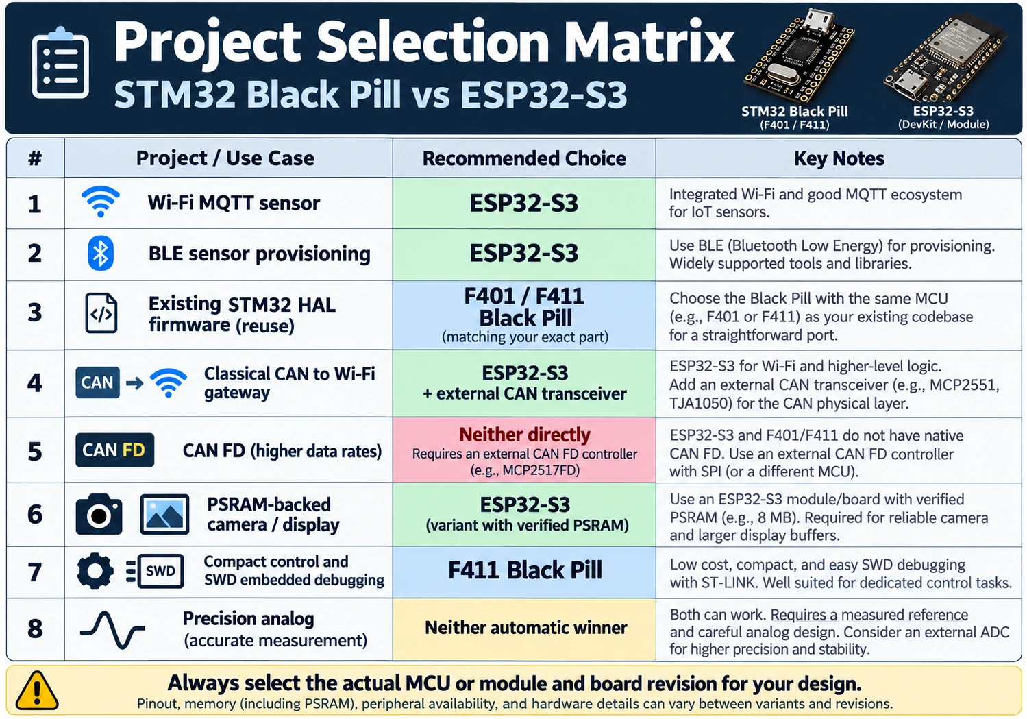
| Project or requirement | Better starting point | Reason |
|---|---|---|
| Sensor node publishing MQTT over Wi-Fi | ESP32-S3 | Wireless stack and 2.4 GHz radio are built in |
| Compact timer/interrupt controller with STM32 HAL | STM32F411 Black Pill | Mature Arm toolchain and direct control of peripherals |
| Classical CAN to Wi-Fi gateway | ESP32-S3 + CAN transceiver | Native TWAI plus Wi-Fi; confirm bus termination |
| CAN FD controller | Neither alone | Select a device with CAN FD controller or add suitable external controller and FD transceiver |
| Existing F401/F411 product maintenance | Same exact Black Pill/STM32 MCU | Firmware, pin and toolchain compatibility |
| Camera or graphics with large buffers | PSRAM-equipped ESP32-S3 | More available memory and suitable peripheral ecosystems |
| Battery product with simple control only | Measure both; consider other STM32 low-power families | Board power architecture matters more than brand |
| Bluetooth LE sensor/provisioning | ESP32-S3 | Integrated BLE, no extra radio module |
| Precision analog measurement | Depends; consider an external ADC | Reference, calibration, noise and analog front end dominate |
| Industrial motor control with specialized comparators and synchronized ADC | Consider STM32G4 instead | Better peripheral match than assuming F411 or S3 is ideal |
For readers starting with STM32 generally, our Best STM32 Development Boards guide also covers Nucleo boards with integrated debuggers. If your project involves motor control, fast analog processing or CAN FD, compare the Black Pill against the specific STM32G4 peripheral set instead of forcing this two-board comparison to answer a different question.
Buying checklist: six things to verify
- Exact silicon and module: F401CC versus F401CE versus F411CE; or ESP32-S3-WROOM with stated flash and PSRAM. Read markings, not just the listing headline.
- Board revision and connector map: LED, boot button, USB wiring, oscillator and available pins must match the vendor’s actual schematic.
- Non-negotiable peripherals: USB mode, native TWAI/classic CAN, ADC channels, PWM and DMA cannot be inferred from generic brand or CPU name.
- Programming recovery: budget for an SWD adapter on Black Pill; identify the S3’s native USB versus USB-UART paths and boot/download buttons.
- Voltage and power budget: 3.3 V logic, adequate regulator, radio current bursts and safe analog input limits.
- Firmware maintenance: pick the toolchain, updates, logging and debug workflow you can realistically support in six months.
If the seller cannot identify the board revision or memory configuration and your project depends on it, prefer a documented board even if it costs more.
Troubleshooting common assumptions
“My Black Pill USB powers on, but the PC finds no device”
The board being powered through USB does not prove it is running USB firmware or in a suitable factory bootloader mode. Verify the data cable, the actual F401/F411 variant, BOOT0, target USB DM/DP routing and supported DFU procedure; use SWD to confirm the MCU is alive. Do not copy STM32F103-specific advice to an F411 without checking the relevant ST documentation.
“My ESP32-S3 is connected but the wrong USB serial port appears”
Some S3 boards present a USB-to-UART bridge on one physical socket and native USB on another. The selected board configuration, firmware USB mode and operating-system driver determine the visible port. Check the board manual and the ESP-IDF/Arduino-ESP32 upload configuration before changing GPIO or burning eFuses.
“The ESP32-S3 has 45 GPIO, so why can’t I use all of them?”
Because that is a silicon capability figure, not a board-accessible pin count. Module flash and PSRAM connections, boot strapping, USB, JTAG, antenna layout, buttons and LEDs consume or constrain pins. On some octal PSRAM modules GPIO35–GPIO37 are not available for general use. Use the actual module and board schematic, not an arbitrary online diagram.
“Can I connect CAN_H and CAN_L directly to either board?”
No. The ESP32-S3 TWAI controller requires a physical CAN transceiver between the MCU’s logic signals and the differential bus. F401 and F411 lack an internal CAN controller entirely. Correct termination is applied at the physical bus ends, not on every intermediate node.
“Will ESP32-S3 replace every STM32 Black Pill project?”
No. Existing STM32 firmware, timing constraints, toolchain qualification, available package pins and system certification may make a Black Pill or production STM32 more appropriate. Conversely, the S3 saves significant integration work when radio, provisioning and network software are essential.
Final verdict: buy for required features, not the clock sticker
Choose the STM32F411CE Black Pill if you need a compact STM32F4 development platform, already work with CubeMX/HAL, value single-MCU control and can use an SWD debugger. Buy an F401 variant only after checking whether its lower RAM and flash configuration is sufficient.
Choose an ESP32-S3 board if Wi-Fi, BLE, USB Serial/JTAG, high-level integration or larger application buffers are important. For image and display work, choose the flash/PSRAM variant deliberately; for classical CAN, budget an appropriate external transceiver. Remember that S3 has BLE but no Bluetooth Classic and neither S3 nor F401/F411 supplies native CAN FD.
If neither board meets a hard requirement, do not compromise the design to fit the comparison. A well-chosen STM32G4, another STM32 family or a purpose-built communication controller may be the better engineering decision.
Official references and related guides
- ST STM32F401CC product page — F401CC clock and memory capabilities.
- ST STM32F411CE product page — F411CE memory, timers, DMA and USB features.
- STM32F411CE datasheet — actual electrical and pin-level constraints.
- Espressif ESP32-S3 SoC overview — processor, Wi-Fi, BLE and peripherals.
- ESP32-S3 Series datasheet — GPIO restrictions and interfaces.
- ESP32-S3-DevKitC-1 v1.1 user guide — board-specific USB and pin routing.
- Espressif USB DFU guide for ESP32-S3 — OTG PHY routing limitations.
- STM32F401 vs STM32F411 Black Pill comparison — related on-site guide.
- STM32F411 Black Pill pinout — GPIO, USB, Arduino core and SWD.