An STM32 Blue PillAliExpress price and a Raspberry Pi Pico 2AliExpress price can both read sensors, switch relays, generate PWM and run embedded software without a Linux operating system. That makes them appear interchangeable in beginner shopping lists. They are not. The Blue PillAliExpress price is a compact, inexpensive board built around an STM32F103C8-class Cortex-M3 microcontroller, while the official Pico 2 uses Raspberry Pi’s substantially newer RP2350A, with far more memory, dual-core processing and programmable I/O (PIO).
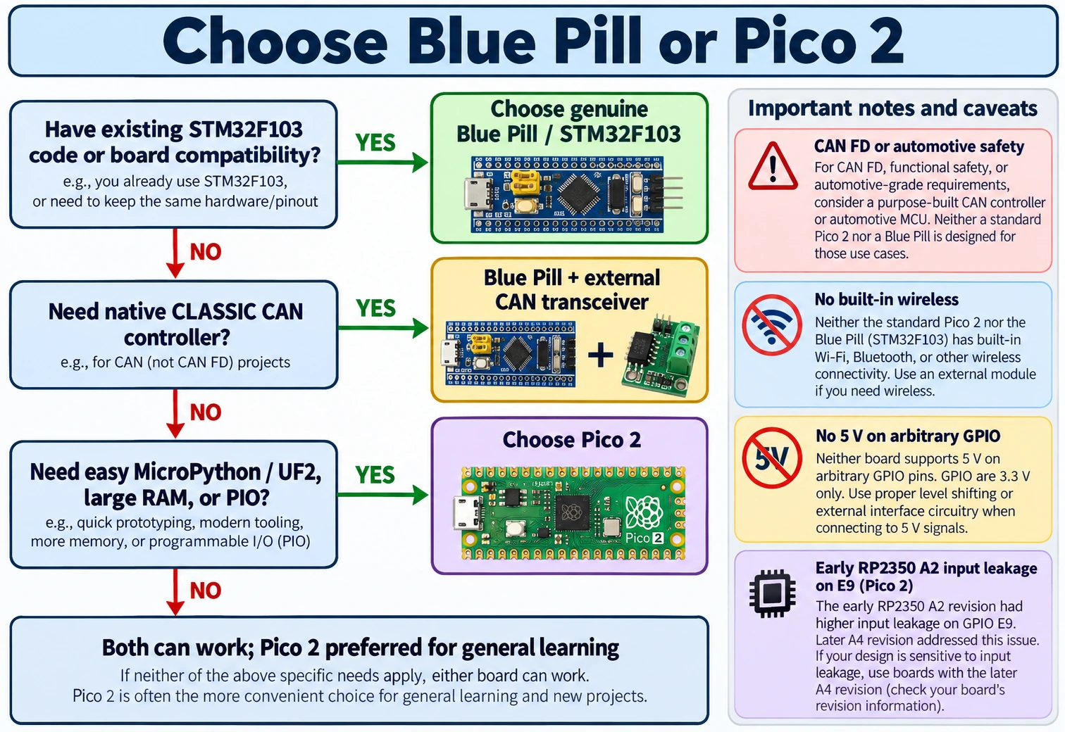
Quick answer: For most new learning, MicroPython, USB and unusual digital-interface projects, buy the Pico 2. Its 150 MHz dual-core architecture, 520 KB SRAM, 4 MB board flash and BOOTSEL USB flashing make experimentation less frustrating. Choose a genuine STM32F103C8 Blue Pill when you specifically need the STM32 ecosystem, an existing F103 design, the device’s advanced-control timer, or its on-chip classic CAN controller with an appropriate external transceiver. Neither board offers built-in Wi-Fi: that is a separate Pico 2 W product.
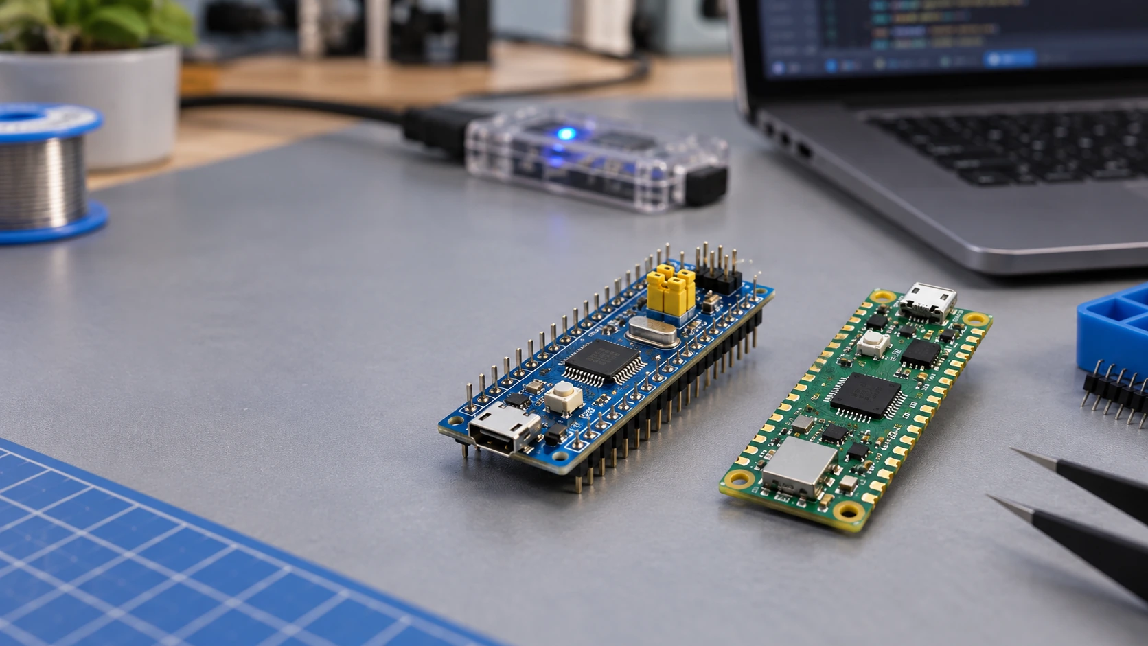
The right purchase depends less on MHz than on peripherals, software, reliability, debugging and the wiring of the exact board you receive. This guide compares an ordinary STM32F103C8T6 Blue Pill against the official non-wireless Raspberry Pi Pico 2, not a Black Pill, Pico 1, Pico 2 W or an unverified RP2350 clone.
Specifications at a glance
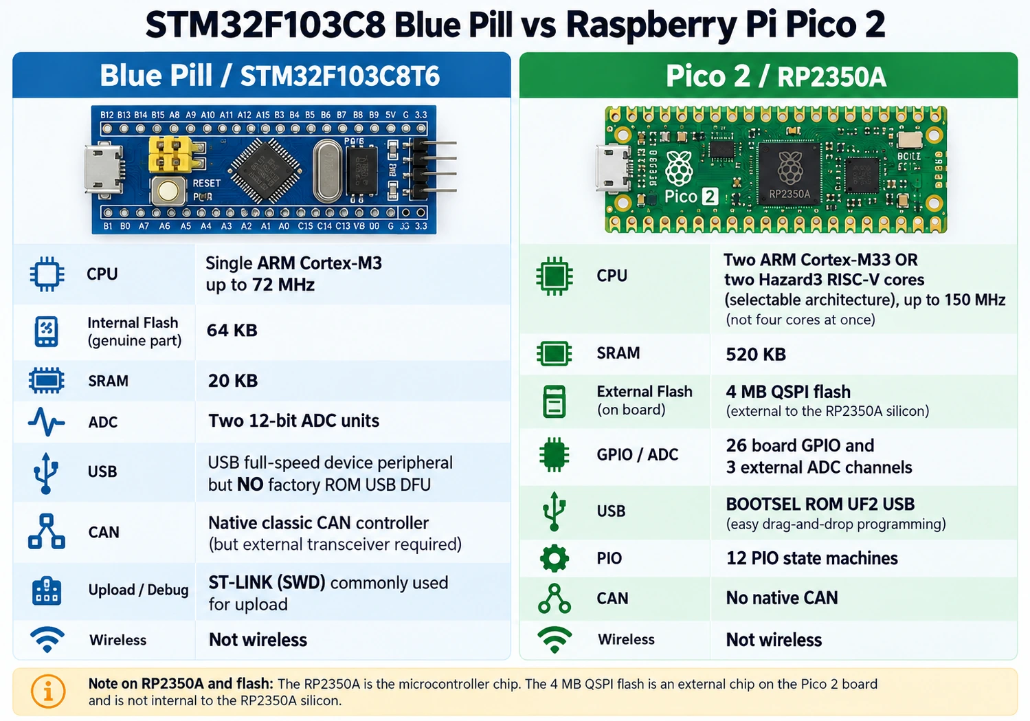
| Feature | STM32 Blue Pill (STM32F103C8T6) | Raspberry Pi Pico 2 (RP2350A) |
|---|---|---|
| CPU | Single Arm Cortex-M3 | Two Arm Cortex-M33 cores or two Hazard3 RISC-V cores, architecture selected rather than four CPUs at once |
| Nominal maximum CPU clock | 72 MHz | 150 MHz |
| Flash | 64 KB nominal internal flash on a genuine C8 | 4 MB external QSPI flash on the official board |
| SRAM | 20 KB | 520 KB |
| Board GPIO | Many LQFP48 MCU signals brought to headers; practical availability depends on board | 26 user-accessible multifunction GPIO, three exposed ADC inputs |
| ADC | Two 12-bit ADC units, multiplexed channels | 12-bit ADC; three user-exposed channels on Pico 2 board |
| USB hardware | Full-speed USB device peripheral | USB 1.1 controller/PHY with device and host support |
| Factory USB programming | No native USB DFU ROM bootloader on F103C8 | BOOTSEL ROM USB mass-storage/UF2 drag-and-drop |
| Debug | SWD on PA13/PA14, external ST-LINK typical | SWD; a separate debug probe or another Pico is useful |
| CAN | On-chip classic CAN 2.0B controller, transceiver required | No native CAN controller; external controller needed |
| Custom hardware protocols | Timer, DMA, SPI, I²C, USART, USB | 12 programmable I/O state machines, timer/DMA and standard serial buses |
| Wireless | None on typical Blue Pill | None on Pico 2; Pico 2 W is a different board |
| Typical software | STM32CubeIDE/CubeMX, HAL/LL, bare metal, STM32duino | MicroPython, official C/C++ SDK, supported Arduino cores |
This table is a board-level purchasing comparison, not a cycle-for-cycle benchmark. The Blue Pill market includes clones and chips with misrepresented flash size; the Pico 2’s larger flash is external and uses XIP/caching, not equivalent to 4 MB of on-chip STM32 flash. Verify exact device and board markings before committing a design.
CPU performance: 72 MHz versus 150 MHz is only the beginning
The Blue Pill’s Cortex-M3 is a well-understood 32-bit core with a good interrupt controller and deterministic embedded programming model. It is sufficient for PID loops, sensors, small control panels, displays and communication at realistic rates. A properly written interrupt-driven F103 project can be far more reliable than inefficient code on a much faster MCU.
RP2350 adds two processing cores, a Cortex-M33 architecture option with DSP and floating-point support, more modern memory and bus resources, and its distinctive alternative dual Hazard3 RISC-V mode. You do not get two Cortex-M33 cores plus two RISC-V cores operating concurrently. Firmware selects an architecture, and software support and toolchains differ by architecture. For straightforward beginner projects, use the established Arm path unless there is a concrete reason to explore RISC-V.
For CPU-heavy work, the Pico 2 generally offers far more headroom. But avoid simplistic claims such as “twice the MHz therefore twice the speed”. Memory access, cache misses, PIO offload, DMA, floating-point operations, compiler flags, RTOS design and interrupt priorities affect actual throughput. Benchmark your own workload instead of equating maximum core clocks to universal performance.
A practical control-loop calculation
Suppose a project samples inputs at 2 kHz and gives each iteration 500 microseconds. A hypothetical 10,000-cycle computational task consumes around 139 µs at 72 MHz or 67 µs at 150 MHz if cycles-per-task are unchanged. They will not be unchanged between Cortex-M3 and Cortex-M33, nor when memory/peripheral waits occur. The calculation is a first-pass budget, not a benchmark result.
For hard real-time motor-drive timing, dedicated PWM, complementary outputs, dead-time insertion, break input and ADC triggering may matter more than raw arithmetic. The F103’s TIM1 advanced-control timer is useful here, although for a new demanding motor-control design a modern STM32G4 is typically a stronger comparison than either board.
Memory: why it changes what you can build
64 KB of program flash and 20 KB SRAM is enough for many small C applications but can become restrictive once you add USB classes, buffering, a graphics library, TLS, large lookup tables, logging or an RTOS. Always read the actual linker map for a Blue Pill build. Some inexpensive boards may contain a different chip or nonstandard flash configurations; do not rely on a claimed 128 KB unless your actual device is identified and validated.
Pico 2 offers 520 KB SRAM, around 26 times the Blue Pill’s 20 KB, plus 4 MB of board flash. This is particularly helpful for MicroPython’s runtime, framebuffers, sampled data, MIDI/audio buffers, protocol decoders and firmware features that need more than a few kilobytes of working RAM. Not all the memory is necessarily available as a single block to your application; runtime and SDK allocation still matter.
The external flash’s execute-in-place (XIP) design is another difference. A normal Pico application generally executes code through a cache backed by the external QSPI flash. Code that must run while reprogramming flash, or that has strict time bounds under contention, may need to live in RAM. STM32F103 normally executes from internal flash, with a different set of wait-state and erase/program constraints.
Memory-sizing checklist
Before picking the cheaper-looking board, add up code, stacks, sensor buffers, USB descriptors, communication queues and worst-case dynamic allocation. Account for two stacks if using both Pico cores, guard space for interrupt nesting, and leave upgrade headroom. For a 10 kB embedded C application the Blue Pill may be fine; for a Python interpreter with sizeable buffers the Pico 2 is the natural fit.
GPIO: pin count, voltage tolerance and physical access
Both platforms are fundamentally 3.3 V systems, but their GPIO electrical limits are not interchangeable. Certain STM32F103C8 pins designated FT in the exact ST datasheet can accept 5 V signals when the specified digital-input conditions are met. Other pins—including ADC inputs—are not 5 V tolerant. The board itself runs at 3.3 V logic and a USB connector carrying 5 V does not turn every MCU pin into a 5 V input.
On the Pico 2, the RP2350A GPIO bank runs at 3.3 V. The board’s VSYS power input can accept a wider supply range, but that is not permission to drive GP pins at 5 V. Use compatible sensors, common ground, a divider for analog voltages, or a suitable logic translator for digital interfaces when needed. A 5 V I²C pull-up is not made safe merely because a Pico is powered from USB.
The official Pico 2 board exposes 26 multifunction GPIO pins across its edge connections. Three of its ADC channels are presented for normal external use; other RP2350 signals serve board functions. On a Blue Pill, GPIO functions such as PA13/PA14 are reserved for SWD during development, PC13 commonly drives the LED, PA11/PA12 serve USB, and BOOT0 is a boot-selection pin, not an ordinary general-purpose port in the same sense.
Do not copy physical header numbers from one board onto the other. The Pico 2’s numbered 40-pin layout is not an STM32 Blue Pill pinout, and Blue Pill vendors may choose slightly different component placement. For wiring, follow labels such as GP4, GP5 or PB6 and the specific board documentation.
Analog inputs: useful on both, different trade-offs
The F103C8 has two 12-bit ADC units sharing multiplexed external channels. An F103 can provide more analog-capable signals than the three exposed Pico 2 analog inputs, but acquisition time, source impedance, calibration, analog supply noise and channel switching all matter. The Pico 2 also has a 12-bit ADC, with three normal externally available channels on the standard board. Neither board should be assumed to be a high-accuracy benchtop ADC without a measured noise and reference budget.
For 0–5 V analog sensors, a correctly calculated resistor divider and adequate acquisition time may be enough. For precision acquisition or high-speed synchronized measurement, consider a dedicated external ADC or a more analog-oriented STM32G4, rather than choosing solely by the advertised ADC bit depth.
USB: the Pico 2 has the simpler first-day experience
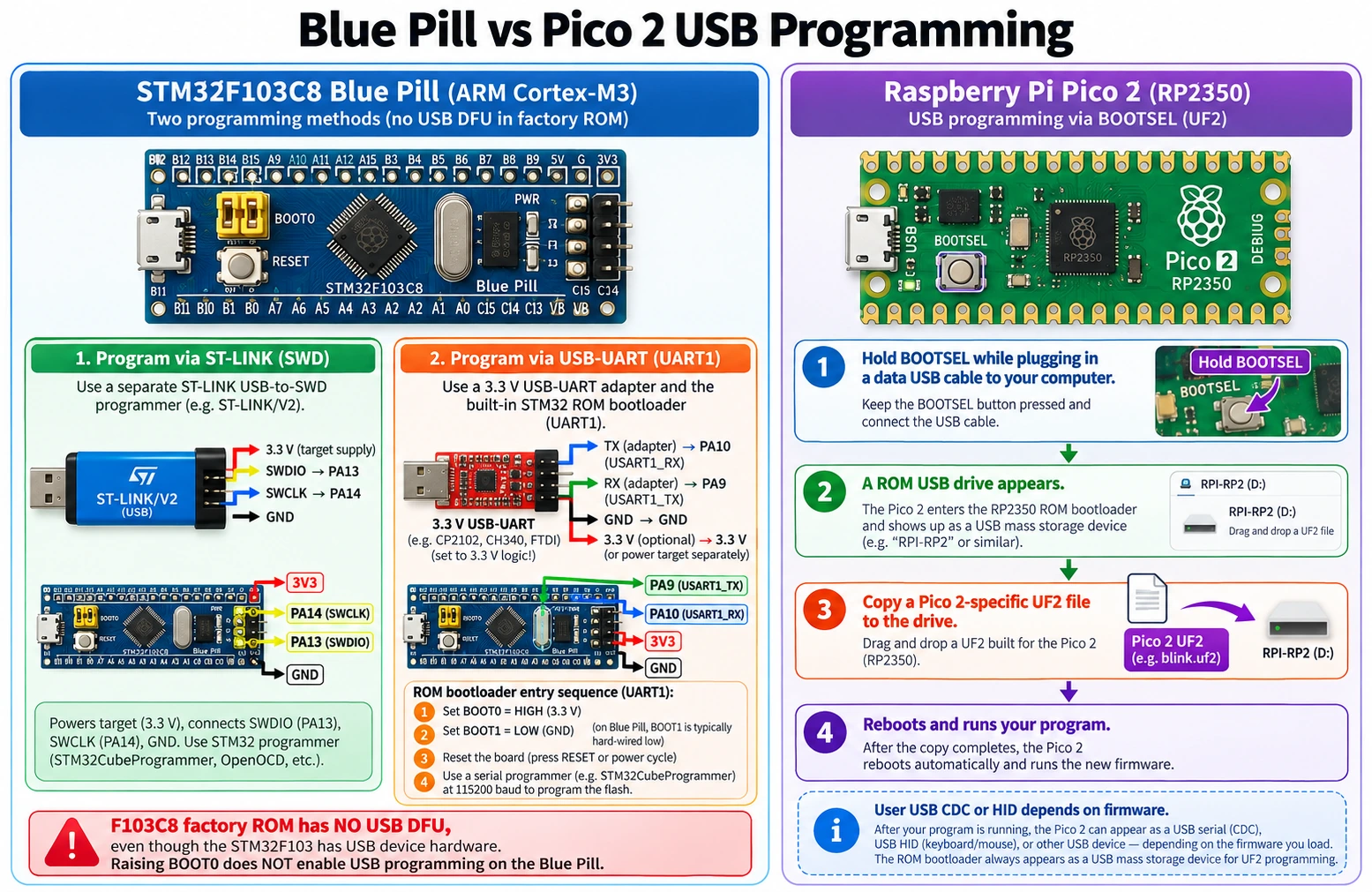
This is one of the largest usability differences. The STM32F103C8 includes a USB full-speed device peripheral and a typical Blue Pill has a Micro-USB connector wired to PA11/PA12. But its factory system-memory bootloader does not offer USB DFU. Plugging in an unprogrammed Blue Pill therefore does not guarantee a USB programming drive or serial port. For a reliable first upload, use an ST-LINK over SWD or the factory USART1 serial bootloader using a 3.3 V USB-UART adapter.
A Blue Pill may also require attention to the well-known external USB D+ pull-up resistor on certain board revisions. Even after valid firmware is installed, USB enumeration requires the correct 48 MHz clock and a firmware USB device stack. A power LED coming on tells you almost nothing about whether USB communication is working.
On the Pico 2, holding BOOTSEL while connecting USB enters the ROM-based USB programming mode. Your computer exposes a device on which you can place an appropriate UF2 firmware. For a first MicroPython project, flash the Pico 2-specific MicroPython image and then connect with Thonny or another supported serial REPL tool. Do not install a UF2 made for the original Pico/RP2040 and assume it is interchangeable.
The Pico 2’s USB controller can operate as host or device when supported by your firmware and hardware. That does not mean your application automatically implements a mass-storage drive, keyboard, serial device or host driver. The BOOTSEL programming interface is a ROM feature; application USB classes must still be written or supplied by a library.
Programming toolchains: which learning curve do you want?
Blue Pill: STM32CubeMX and STM32CubeIDE
For learning register-level MCU design, DMA, timer triggering and peripherals from a manufacturer’s reference manual, STM32 remains excellent. In the current STM32CubeIDE 2.x workflow, STM32CubeMX is a separate application for the classic generation path: configure clocks and pin functions in CubeMX, generate an STM32CubeIDE project, import it in CubeIDE, build and debug. Older tutorials showing an embedded CubeMX inside CubeIDE can mislead beginners.
You can also use STM32duino with Arduino IDE, which is less intimidating for basic sketches. However, library compatibility with a small-memory F103 and the specific board definition must be checked. For advanced projects, understanding the F103’s clock tree, PA13/PA14 SWD, GPIO alternate functions and boot configuration saves time in the long run.
Pico 2: MicroPython, C/C++ and Arduino
Raspberry Pi publishes an official C/C++ SDK, examples and MicroPython images. Beginners can learn with MicroPython and move to C/C++ for tighter real-time control. Supported community Arduino cores also exist, but installation procedures and supported CPU-architecture options belong to the chosen core/version rather than to Raspberry Pi’s ROM bootloader itself.
MicroPython is productive for I²C sensors, displays, text output and simple control. But garbage collection, interpreted overhead, library implementation and scheduler timing can matter. For a guaranteed timing-critical pulse stream, move the pulse generation to a PIO state machine or hardware PWM and keep Python out of the critical edge timing.
Two first LED examples
On a standard Blue Pill, the user LED is commonly attached to PC13 and active-low; pulling it low switches it on. This STM32duino example relies on the correct board definition and assumes an onboard LED at PC13:
// STM32F103C8 Blue Pill; common active-low PC13 LED
const int ledPin = PC13;
void setup() { pinMode(ledPin, OUTPUT); digitalWrite(ledPin, HIGH); }
void loop() {
  digitalWrite(ledPin, LOW);  delay(500);
  digitalWrite(ledPin, HIGH); delay(500);
}
A Pico 2 MicroPython LED test can instead use the board’s LED alias:
from machine import Pin
from time import sleep
led = Pin("LED", Pin.OUT)
while True:
    led.toggle()
    sleep(0.5)
These examples are illustrative and not hardware-tested for this article. The Pico example assumes a current, correct Pico 2 MicroPython UF2, while the Blue Pill example assumes a supported STM32duino core and a typical PC13 LED layout. If an LED does not blink, first verify the selected board, uploaded firmware and its physical LED routing before changing the clock or the pinout.
PWM and custom protocols: STM32 timers versus Pico PIO
The STM32F103 contains rich timer hardware including general-purpose counters, input capture, output compare, PWM channels and the advanced timer. Those are ideal for encoder counting, motor control, accurately timed measurements and synchronized ADC sampling. Hardware PWM keeps edge timing independent of your application loop. Several Blue Pill projects can be built with no custom pulse-generation code once the timer’s prescaler, period, output compare and alternate-function routing are correct.
The Pico 2 also has hardware PWM but adds programmable I/O (PIO): three blocks with a combined 12 state machines. PIO is purpose-built for timing-oriented digital interfaces: WS2812 LEDs, custom shift registers, data sampling and unusual bus signalling. It can turn a timing-sensitive bit-banging problem into a small autonomous program with DMA providing data.
PIO does not make every protocol trivial: you must design state-machine instructions, FIFO flow, DMA and CPU-side behaviour correctly. Likewise, STM32 DMA and advanced timers can solve problems that do not need PIO. The practical distinction is which hardware architecture maps more naturally to the protocol you’re implementing.
Example: 1,000 samples per second with timestamped data
At 1 ksample/s, a 2-byte ADC sample is only 2 kB/s before metadata. Either board has adequate CPU throughput. What matters is whether samples need stable acquisition intervals, buffering during USB transfers, calibration, multiple synchronized ADCs or long-duration storage. An F103 timer-triggered ADC with DMA is a robust fit for deterministic sampling. A Pico 2 with ample RAM can buffer more data and use PIO for related digital captures, but check analog bandwidth and jitter against real requirements.
Example: WS2812 strip with other work in parallel
Pico PIO is very attractive for long addressable-LED strips because it drives precise waveforms independent of most application code. F103 can also use SPI encoding, a timer and DMA, or optimized code. Both approaches require actual voltage-level and power-supply engineering; the MCU pin should not supply the strip’s operating current.
CAN bus, UART and networking: where the Blue Pill wins outright
A genuine F103C8 has an on-chip classic CAN controller (CAN 2.0B). That is significant for automotive/industrial hobby projects or maintaining existing classic-CAN designs. Add an appropriate external CAN transceiver and proper bus termination/grounding; the MCU TX/RX signals must never be connected directly to CAN_H and CAN_L. Check whether the desired alternate functions conflict with USB or other resources on the exact package and board.
The RP2350A does not include a native CAN controller. A Pico 2 can communicate over CAN using a suitable external SPI CAN controller plus a transceiver, or in some projects via sophisticated PIO software. For CAN FD, select a CAN FD-capable controller and transceiver; an old MCP2515-based classic CAN module does not magically support CAN FD. For a dedicated vehicle interface, an STM32G4 with FDCAN or a purpose-designed external controller may be the more appropriate modern platform.
Both boards support UART, SPI and I²C, but controller counts and pins differ. The Pico 2 officially provides two UART, two SPI and two I²C controllers plus PIO. STM32F103’s exact available peripheral instances depend on package and pin multiplexing. Count the independent ports you need simultaneously, not the number of interface names printed in a product advertisement.
Neither board includes Ethernet PHY/RJ45 or Wi-Fi on its standard version. A Pico 2 W includes wireless connectivity, but buying a Pico 2 does not. The Blue Pill requires external networking hardware as well. USB itself is not a substitute for Ethernet, and not every USB project has a ready-made network class implementation.
Power and 5 V interfaces: avoid a costly misunderstanding
The Blue Pill’s STM32F103 MCU is specified for a 2.0–3.6 V supply range, while the Pico 2 board’s VSYS can accept approximately 1.8–5.5 V because the board contains a power regulator. You are comparing a chip supply specification with a board input power specification: they are not interchangeable. A Blue Pill board may also have a 5 V input through its own regulator, depending on the PCB design, but never assume that 5 V belongs on the STM32’s 3V3 pin.
For battery projects, compare complete-board current, regulator quiescent current, LEDs, oscillator settings and firmware sleep modes. Bench power figures from an arbitrary clone are a poor proxy for a properly designed low-power PCB. Both MCU families support lower-power operation, but a development board with a glowing power LED and an always-running USB connection can consume much more than the MCU’s standby specification.
On Pico 2, use VSYS for a suitable external input supply and obey its documentation when USB and another supply may be present. On the Blue Pill, power according to the specific board schematic; some clones have weak regulators or questionable USB-power arrangements. Shared ground and accurate voltage limits are essential for either board.
Debugging, reliability and long-term maintenance
A Blue Pill is most comfortably developed with an ST-LINK debugger over SWD: PA13 SWDIO, PA14 SWCLK, common ground, a valid target supply and optionally NRST. This gives breakpoints, memory inspection, watchpoints and recovery from firmware that disrupts boot or clock configuration. Cheap ST-LINK V2 clones use inconsistent connector pin numbering; wire by documented signal labels, not by copying a photograph of a different clone.
Pico 2 has a BOOTSEL recovery path and SWD debugging. The USB UF2 workflow is excellent for loading firmware, but drag-and-drop flashing is not a substitute for source-level debugging. You may use a Raspberry Pi Debug Probe or an appropriate SWD interface and compatible software. For dual-core debugging, verify that your toolchain understands the chosen core architecture and which core you are actually inspecting.
There are two hardware-purchasing concerns in 2026:
- Blue Pill authenticity. The market includes genuine STM32 parts as well as clones and lookalikes with different flash/USB/debug behaviour. Verify the chip identity, flash specification and actual power/USB circuitry. A price far below a reputable authorised-source board is not proof of a genuine ST device.
- RP2350 silicon revisions. Early A2 silicon has the documented RP2350-E9 GPIO input-leakage issue, which can affect weakly driven input states. Later A4 production silicon addresses this issue. For a design relying on high-impedance sensing, obtain the exact revision or follow Raspberry Pi’s current datasheet and errata instead of assuming all Pico 2 boards behave identically.
The E9 issue is not a reason to condemn every Pico 2 bought today. It is a reason to check the actual silicon stepping when electrical-input behaviour matters. Similarly, a genuine ST part with verified board hardware should not be judged by the failings of cheap lookalike Blue Pill assemblies.
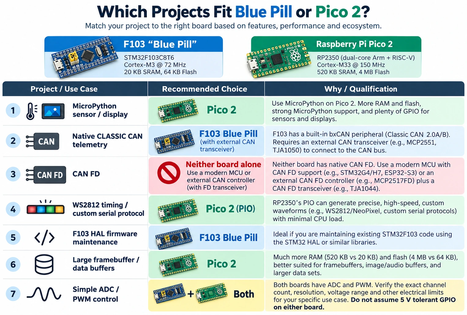
Which board should you use for each project?
| Project | Better initial choice | Technical reason and qualification |
|---|---|---|
| Learn MicroPython with sensor readings | Pico 2 | Official UF2 installation and substantially more SRAM |
| Reuse an existing F103 HAL project | Blue Pill | Compatible STM32F103 peripheral/register ecosystem, assuming exact device |
| Classic CAN telemetry interface | Blue Pill | Native bxCAN controller; external transceiver still required |
| CAN FD diagnostic interface | Neither as-is | Consider MCU with FDCAN or a separate CAN FD controller/transceiver |
| Precision PWM or encoder capture | Depends | F103 advanced timer is strong; choose on required timer functions |
| WS2812/unique digital interface | Pico 2 | PIO state machines can offload custom timing |
| USB HID/MIDI beginner experiment | Pico 2 | Simple UF2 recovery and ample resources; software USB class still needed |
| Three or fewer analog sensors | Both | Compare reference noise, timing and ADC configuration |
| More analog channels on minimal hardware | Blue Pill potentially | F103 ADC mux offers more signals; verify package/pin availability |
| Large display framebuffer or data buffer | Pico 2 | 520 KB SRAM gives far more room |
| Battery sensor with radio | Neither base board | Evaluate Pico 2 W or dedicated low-power wireless MCU and measured consumption |
| Home-built ECU / motor-drive research | Prefer dedicated controller evaluation | F103 timers useful, but protection, automotive supplies and modern G4 features matter |
Three realistic builds, worked through
Build A: motorcycle coolant-temperature monitor. A thermistor and voltage divider are simple for either ADC. If the display requires a clean UI, logging or flexible serial support, Pico 2 has room to spare. If you want direct classic CAN listening from an existing network with the minimum controller ICs, Blue Pill’s built-in CAN gives it an advantage, provided you add the right transceiver and electrical protection. A motorcycle’s electrical system requires transient, reverse-polarity and grounding protection regardless of MCU choice.
Build B: programmable 16-channel LED controller. Pico 2 is attractive for PIO-driven addressable LEDs and complex animation buffers. A normal PWM lamp dimmer might be equally easy with Blue Pill timers. If LEDs are 12 V or draw meaningful current, both need suitable MOSFET drivers and dedicated power wiring.
Build C: precision industrial temperature logger. Software memory alone does not determine precision. Use a calibrated sensor, appropriate ADC/reference, input filtering, accurate timekeeping and electrical isolation where needed. Blue Pill timer-triggered ADC/DMA is strong for synchronized data; Pico 2 makes buffering and USB transfer easier. Choose an MCU only after specifying sample rate, allowable error, input common-mode range and long-term drift.
First-day setup costs and workflow friction
The price of a board is not your total project cost. On a Blue Pill, budget for ST-LINK or an appropriate USB-UART programmer, USB cables, a breadboard, 3.3 V sensors, and possibly time resolving a nonstandard board. A genuine, properly documented STM32 Nucleo may be a better educational investment than repeated troubleshooting of a suspiciously cheap clone.
For Pico 2, many basic experiments need only a data-capable USB cable and a computer with a compatible toolchain. A dedicated debug probe remains worthwhile for complex C/C++ work. If you need wireless, price Pico 2 W specifically; and if you need CAN, include controller/transceiver cost instead of assuming its two SPI interfaces eliminate that hardware.
Buying advice: If you are starting from zero, choose the official Raspberry Pi Pico 2 for a modern general-purpose MCU playground. If you want to learn STM32 professional development, choose an ST Nucleo board for straightforward debugging; buy the Blue Pill when the F103 itself, compatibility or its classic CAN controller is specifically relevant. Avoid making a new hardware architecture depend on undocumented flash capacity or clone-specific pinouts.
Common misconceptions and troubleshooting
“The Blue Pill powers up over USB, but my PC cannot find it.” Power does not mean the factory F103 has a USB mass-storage bootloader. Try ST-LINK over SWD or the documented USART1 ROM bootloader, confirm the USB pull-up and firmware if using USB CDC.
“Pico 2 has four processors, so I can run four programs.” No: the hardware provides a selectable dual-core architecture, either two Arm Cortex-M33 or two Hazard3 RISC-V cores. Manage inter-core data and synchronization explicitly if using both cores.
“Pico 2 has 4 MB of RAM.” It has 520 KB SRAM and 4 MB flash on the official board; they serve very different purposes.
“Both boards have 5 V pins, so their GPIO is 5 V tolerant.” No. Board input rails are not GPIO ratings. Use per-pin STM32 FT rules, and treat Pico 2 GPIO as 3.3 V logic.
“Pico 2 supports CAN because its PIO can implement protocols.” Flexible digital timing does not replace CAN physical-layer signalling, bus arbitration robustness and appropriate controller/transceiver design. A proven external CAN controller is usually easier and safer for serious CAN work.
“The F103 has native CAN, so I can connect to a car directly.” No. You still need a compliant transceiver, proper termination and protection, and must respect CAN network electrical requirements. Sensitive vehicle systems should not be used as an unprotected electronics playground.
“My Pico 2 input seems stuck HIGH.” Check wiring, internal pulls, external source impedance and the actual RP2350 stepping. On affected A2 silicon, E9 input leakage may matter; newer silicon has the fix.
“The Pico has no user LED on GP25.” The non-wireless official Pico 2 has an LED tied to GP25. Code that uses Pin("LED") is easier to adapt across Pico boards; do not assume Pico 2 W follows the identical LED hardware path without checking its board documentation.
Final verdict
For someone who wants one versatile, inexpensive development board to learn with in 2026, Pico 2 wins on ease of first upload, memory, dual-core headroom, MicroPython support and PIO. It makes it easier to concentrate on the project rather than on first establishing a working programming connection.
The Blue Pill still has a valuable role. It is compact, documents the classic STM32F103 platform well, offers good real-time timers, and provides an actual on-chip classic CAN controller. Existing F103 designs and STM32-oriented study are sound reasons to use it. But its small memory, often inconsistent clone boards and less friendly factory upload route are drawbacks for a newcomer.
These are not the only sensible choices. If your specifications demand CAN FD, many high-speed ADCs, advanced power electronics, guaranteed industrial support or built-in wireless, compare purpose-built STM32G4, newer STM32 lines or wireless microcontrollers rather than forcing either entry-level board to fit.
Official documentation and further reading
- Raspberry Pi Pico 2 official product and specification
- Pico-series board documentation and pinout
- Raspberry Pi RP2350 silicon datasheet
- Pico 2 board datasheet
- STM32F103C8 manufacturer product page
- Raspberry Pi Pico MicroPython setup
- Blue Pill versus other STM32 development boards
- STM32 beginner setup and programming
Editorial verification note (October 2026): This comparison uses the official Pico 2/RP2350 specifications and genuine STM32F103C8 specification. The sample sketches and benchmark illustration were reviewed for logic but not bench-tested on both boards for this article. Actual current consumption, ADC noise, debug behaviour and GPIO revision details should be verified on the physical board being used.