The ESP-01AliExpress price and ESP-01SAliExpress price are tiny ESP8266AliExpress price Wi-Fi modules with only eight pins, but they can run complete Arduino, MQTT and simple ESPHome projects without another microcontroller. The two easiest user GPIOs are GPIO0 and GPIO2, although both are also boot-strapping pins and must be HIGH during normal startup. To flash firmware, hold GPIO0 LOW while resetting or powering up the module. TX and RX can also become GPIO1 and GPIO3 after boot, but using them interferes with Serial and programming. The module is 3.3 V only, needs a good power supply capable of handling Wi-Fi current peaks, and has no onboard USB, so flashing requires a 3.3 V USB-to-UART adapter or dedicated ESP-01AliExpress price programmer.
Materials You’ll Need
| Item | Why you need it |
|---|---|
| ESP-01AliExpress price or ESP-01S module | Main ESP8266 Wi-Fi module |
| ESP-01 USB programmer or 3.3 V USB-to-UART adapter | Uploading firmware |
| Stable 3.3 V power supply, 500 mA+ recommended | Reliable Wi-Fi operation |
| USB data cable | Connect programmer to the computer |
| Breadboard / ESP-01 breakout adapter | Makes the unusual 2×4 connector easier to use |
| Dupont jumper wires | Wiring the module |
| Pushbutton | Optional RESET or FLASH button |
| 10 kΩ resistors | Useful for boot/reset pull-ups on custom circuits |
| 100 nF + bulk capacitor | Helps keep the 3.3 V rail stable |
| Multimeter | Useful for checking the 3.3 V supply |
A dedicated ESP-01 USB programmer is by far the easiest option for beginners because it handles the awkward 2×4 pin layout and usually provides the required USB-to-serial interface.
If using a generic USB-to-UART adapter, check its power capability. Many adapters expose a 3.3 V pin but their onboard regulator cannot reliably supply the current peaks produced by an ESP8266 Wi-Fi transmission.
What are the ESP-01 and ESP-01S?
The ESP-01 is one of the boards that made the ESP8266 famous.
It combines:
- ESP8266 Wi-Fi SoC
- PCB antenna
- SPI flash
- 26 MHz crystal
- basic supporting components
- eight external pins
into a module measuring roughly 25 × 14 mm.
The ESP-01S is a later refinement of the same concept.
Both use the same basic ESP8266 architecture:
| Feature | ESP-01 / ESP-01S |
|---|---|
| Processor | Tensilica L106 32-bit |
| CPU speed | 80 MHz / 160 MHz |
| Wi-Fi | 802.11 b/g/n |
| Wi-Fi band | 2.4 GHz |
| Bluetooth | No |
| User-visible pins | 8 |
| Main convenient GPIOs | GPIO0, GPIO2 |
| UART | Yes |
| PWM | Yes |
| ADC inside ESP8266 | 10-bit |
| ADC exposed on ESP-01/S | No |
| Native USB | No |
| Supply | 3.3 V |
| ESP-01S flash | 1 MB default on current Ai-Thinker specification |
The ESP8266 itself has considerably more GPIO and peripheral capability than the ESP-01 exposes.
The limitation is therefore mainly the tiny module package, not the processor.
ESP-01 vs ESP-01S
The pinout is essentially the same, so an ESP-01S can normally replace an ESP-01 electrically.
The important practical differences are board revision and supporting components.
The current ESP-01S design includes onboard boot/reset resistors that make standalone operation easier. Its schematic provides the required biasing around EN, RESET and the ESP8266 boot pins.
Current Ai-Thinker documentation also specifies:
SPI Flash:
8 Mbit
which means:
1 MBOlder ESP-01 modules are less predictable.
Depending on age and manufacturer, they may contain:
512 KB
1 MB
or another flash configuration.
So an old ESP-01 should not automatically be configured as 1 MB simply because a modern ESP-01S uses 1 MB.
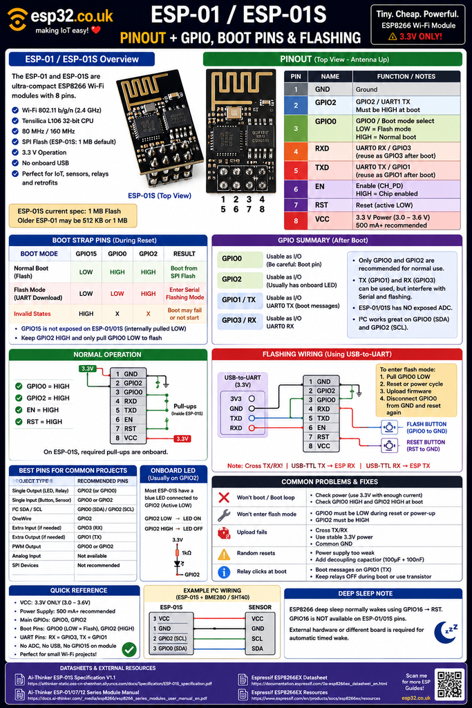
ESP-01S pinout
The current ESP-01S exposes exactly eight pins:
| Pin | Name | Function |
|---|---|---|
| 1 | GND | Ground |
| 2 | GPIO2 | GPIO2 / UART1 TX |
| 3 | GPIO0 | GPIO0 / boot selection |
| 4 | RXD | UART0 RX / GPIO3 |
| 5 | TXD | UART0 TX / GPIO1 |
| 6 | EN | Chip Enable / CH_PD |
| 7 | RST | Reset, active LOW |
| 8 | VCC | 3.3 V supply |
That tiny pinout is simultaneously the biggest advantage and biggest limitation of the ESP-01 family.
Only:
GPIO0
GPIO2
are exposed as uncomplicated user GPIO pins.
TX and RX can also become GPIOs, but doing so creates additional complications.
Pin functions explained
VCC
VCC powers the module.
Use:
3.3 Vnot 5 V.
The current ESP-01S specification recommends a 3.3 V source capable of at least:
500 mAThis does not mean the module continuously consumes 500 mA.
It means the power source should have enough headroom to deal with short current peaks when the Wi-Fi transmitter operates.
A weak supply is one of the most common causes of unstable ESP-01 projects.
GND
GND is the common electrical reference.
When using an external USB-to-UART adapter:
ESP-01 GND
USB-UART GND
External PSU GND
must all be connected together.
Without a common ground, UART communication will not work correctly.
EN / CH_PD
The pin now normally labelled:
ENwas traditionally called:
CH_PDor:
CHIP_ENIt is the chip-enable input.
EN HIGH
→ ESP8266 enabled

EN LOW
→ chip disabled
A functioning module therefore requires EN to be HIGH.
Modern ESP-01S modules provide the appropriate onboard pull-up.
Older ESP-01 designs and custom ESP8266 circuits may require an external resistor.
RST
RST is active LOW.
Normally:
RST = HIGHTo reset the module:
RST → GND momentarilyThen release it.
A simple reset button can therefore be connected between:
RST
and
GND
The ESP-01S has an onboard reset pull-up.
GPIO0
GPIO0 is probably the most important ESP-01 pin.
It is both:
a normal GPIO
and:
a boot-mode selection pin.
During reset:
GPIO0 HIGH
→ boot program from flash

GPIO0 LOW
→ enter serial firmware download mode
After normal startup, GPIO0 can be used by the application as a normal GPIO.
This is why GPIO0 is usable, but not completely “safe.”
A sensor, relay module or button that forces GPIO0 LOW while the ESP8266 resets will prevent the normal program from booting.
GPIO2
GPIO2 is also a boot-strapping pin.
For normal operation it must be:
HIGH during startupThe ESP-01S provides a pull-up internally on the module.
After boot it can operate as a normal GPIO.
GPIO2 is therefore commonly used for:
- LED output
- relay control
- OneWire
- I²C
- buttons
- digital sensors
provided connected hardware does not force it LOW during reset.
GPIO2 and the onboard LED
Many ESP-01S modules have an onboard blue LED connected to GPIO2.
The LED is normally active LOW.
That means:
GPIO2 LOW
→ LED ON

GPIO2 HIGH
→ LED OFF
A simple Arduino test is:
#define LED_PIN 2

void setup() {
  pinMode(LED_PIN, OUTPUT);
}

void loop() {
  digitalWrite(LED_PIN, LOW);
  delay(500);

  digitalWrite(LED_PIN, HIGH);
  delay(500);
}
This is the opposite of what beginners often expect from a conventional LED connected between GPIO and ground.
Board clones vary, so check the actual module if the LED behaves differently.
RX is also GPIO3
The pin marked:
RXis:
GPIO3and normally operates as:
UART0 RX
It is required when uploading firmware through a USB-to-UART converter.
After boot, it can technically be reused as a normal GPIO.
But doing that means it can no longer simultaneously operate normally as the serial receive input.
For projects where every pin matters, GPIO3 can provide an extra input/output.
For beginner projects, it is easier to leave it as RX.
TX is also GPIO1
The pin marked:
TXis:
GPIO1and normally operates as:
UART0 TX
The ESP8266 prints boot information through this pin during startup.
This creates a practical warning.
If GPIO1 is connected to something such as a relay, LED driver or external controller, the boot messages may create unwanted pulses on that device.
For that reason GPIO1 is usually best left for:
- programming
- Serial Monitor
- debugging
unless the design specifically accounts for its startup behaviour.
The real ESP-01 GPIO situation
Technically, the module makes four GPIO-capable pins accessible:
GPIO0
GPIO1 / TX
GPIO2
GPIO3 / RX
But practically:
GPIO0
GPIO2
are the main application pins.
The other two are shared with UART0.
A useful way to remember the module is:
| GPIO | Practical rating | Why |
|---|---|---|
| GPIO0 | ⚠️ Good with care | Boot pin |
| GPIO1 / TX | ⚠️ Use with care | Serial TX + boot messages |
| GPIO2 | ⚠️ Good with care | Boot pin + often LED |
| GPIO3 / RX | 🟡 Usable | Serial RX |
There are no completely complication-free GPIOs on an ESP-01.
That is the price of having such a tiny module.
ESP8266 boot pins explained
The complete ESP8266 chip uses three boot-strapping pins:
GPIO15
GPIO0
GPIO2
For normal flash boot they must be:
GPIO15 = LOW
GPIO0  = HIGH
GPIO2  = HIGH
For serial flashing:
GPIO15 = LOW
GPIO0  = LOW
GPIO2  = HIGH
The good news is that the ESP-01/ESP-01S does not expose GPIO15.
The module handles its required LOW state internally.
That leaves only GPIO0 and GPIO2 for the user to worry about.
ESP-01 boot mode cheat sheet
| GPIO0 | GPIO2 | Result |
|---|---|---|
| HIGH | HIGH | ✅ Normal flash boot |
| LOW | HIGH | 🔧 UART flashing/download mode |
| HIGH | LOW | ❌ Invalid/unwanted boot state |
| LOW | LOW | ❌ Not normal firmware flashing |
The rule to remember is extremely simple:
GPIO2 stays HIGH.
GPIO0 decides normal boot vs flashing.
Normal running wiring
For normal operation:
VCC   → 3.3 V
GND   → GND
EN    → HIGH
RST   → HIGH
GPIO0 → HIGH
GPIO2 → HIGH
On a modern ESP-01S, onboard pull resistors already establish much of this state.
That is why an ESP-01S can often run with little more than:
3.3 V
GND
once firmware has been programmed.
External circuits still need to respect GPIO0 and GPIO2 during startup.
Flashing wiring
To upload firmware manually with a USB-to-UART adapter:
| ESP-01 / ESP-01S | USB-UART / supply |
|---|---|
| VCC | Stable 3.3 V |
| GND | GND |
| RX | Adapter TX |
| TX | Adapter RX |
| EN | 3.3 V / HIGH |
| GPIO0 | GND during reset |
| GPIO2 | HIGH |
| RST | Reset normally HIGH |
Remember that UART wiring crosses:
USB-UART TX
→ ESP RX

USB-UART RX
← ESP TX
Never power the ESP-01 from 5 V
This deserves its own section because it is an extremely common mistake.
The ESP-01 is:
3.3 V hardware.
Do not connect:
5 V → VCCand do not feed 5 V logic directly into GPIO0, GPIO2, RX or TX.
A USB-to-UART adapter may have pins labelled:
5V
3V3
Use the correct 3.3 V supply.
Also check the UART logic level.
Some adapters can be powered from 5 V while still outputting 3.3 V UART logic, but that depends on the adapter.
Why cheap USB-UART adapters can cause resets
The ESP8266 draws relatively large current peaks when transmitting over Wi-Fi.
A USB serial adapter’s tiny onboard 3.3 V regulator may only be designed to provide:
50 mAor:
100 mAeven though the adapter has a pin marked 3V3.
Symptoms of inadequate power include:
- random resets
- Wi-Fi disconnects
- boot loops
- firmware uploads failing
- module working until Wi-Fi starts
- garbage appearing in Serial Monitor
wdt reset- exception messages
For reliable development, use:
a proper regulated 3.3 V supply capable of at least 500 mA
and connect its ground to the USB-UART adapter ground.
Recommended power arrangement
A reliable setup looks like:
USB 5 V
   │
Good 3.3 V regulator
   │
   ├──── ESP VCC
   │
 capacitor
   │
  GND

USB-UART TX ───── ESP RX
USB-UART RX ───── ESP TX

All grounds connected
Placing decoupling and bulk capacitance close to the ESP-01 can help prevent short voltage dips.
How to enter flashing mode manually
With everything wired:
- Connect GPIO0 to GND.
- Reset the ESP-01 by briefly pulling RST LOW, or power-cycle it.
- Leave GPIO0 LOW while the bootloader starts.
- Upload the firmware.
- Disconnect GPIO0 from GND.
- Reset the module again.
After the final reset:
GPIO0 = HIGHand the ESP8266 boots the newly uploaded program from flash.
A better FLASH button circuit
Instead of repeatedly moving jumper wires, add a pushbutton:
GPIO0
   │
 FLASH button
   │
  GND
GPIO0 remains pulled HIGH normally.
To enter programming mode:
Hold FLASH
↓
Press RESET
↓
Release RESET
↓
Release FLASH
This is essentially how larger ESP8266 development boards automate or simplify the process.
Dedicated ESP-01 USB programmers
An ESP-01 programmer is much more convenient than building the flashing circuit manually.
The module plugs directly into the programmer’s 2×4 socket.
Depending on the programmer, flashing mode may be selected with:
- a physical switch
- a pushbutton
- automatic reset circuitry
A good programmer also solves the mechanical problem that the ESP-01’s 2×4 connector is inconvenient on a normal breadboard.
For anyone working with multiple ESP-01 modules, a programmer is worth having.
Arduino IDE setup
The ESP-01 uses the normal ESP8266 Arduino core.
After the ESP8266 board package is installed, a practical starting board selection is:
Generic ESP8266 ModuleFor a current genuine ESP-01S:
Flash Size:
1 MB
is appropriate.
For an older ESP-01:
check the actual flash size first.
A sensible starting configuration is:
Board:
Generic ESP8266 Module

CPU Frequency:
80 MHz

Flash Size:
1 MB (ESP-01S)

Upload Speed:
115200
If an old ESP-01 behaves strangely, do not assume it has the same flash chip or flash mode as a recent ESP-01S.
How to check the real flash size
Arduino code can report the flash capacity:
void setup() {
  Serial.begin(115200);

  Serial.println();
  Serial.print("Detected flash size: ");
  Serial.println(ESP.getFlashChipRealSize());
}

void loop() {
}
For a 1 MB module the result should be approximately:
1048576 byteswhich is:
1 MBThis is useful when working with a box of old ESP-01 modules whose exact revision is unknown.
ESP-01S onboard LED blink
A common ESP-01S test program is:
#define LED_PIN 2

void setup() {
  pinMode(LED_PIN, OUTPUT);
  digitalWrite(LED_PIN, HIGH);
}

void loop() {
  digitalWrite(LED_PIN, LOW);
  delay(500);

  digitalWrite(LED_PIN, HIGH);
  delay(500);
}
Remember:
LOW  = LED ON
HIGH = LED OFF
on modules where the onboard LED is wired active LOW to GPIO2.
Using GPIO0 after startup
GPIO0 becomes a normal GPIO after boot.
For example:
#define RELAY_PIN 0

void setup() {
  pinMode(RELAY_PIN, OUTPUT);
  digitalWrite(RELAY_PIN, HIGH);
}

void loop() {
}
But the external relay module must not pull GPIO0 LOW while the ESP8266 resets.
If it does:
ESP boots into flashing modeinstead of running the program.
For this reason GPIO0 often works better with high-impedance inputs than with modules that impose strong startup states.
Using GPIO2 after startup
GPIO2 also becomes normal after startup.
Example:
#define OUTPUT_PIN 2

void setup() {
  pinMode(OUTPUT_PIN, OUTPUT);
}

void loop() {
  digitalWrite(OUTPUT_PIN, HIGH);
  delay(1000);

  digitalWrite(OUTPUT_PIN, LOW);
  delay(1000);
}
Again, GPIO2 must remain HIGH while the ESP8266 resets.
Can ESP-01 use I²C?
Yes.
The ESP8266 implements I²C in software, so the pins can be assigned flexibly.
The obvious ESP-01 pair is:
SDA → GPIO0
SCL → GPIO2
Arduino example:
#include <Wire.h>

void setup() {
  Wire.begin(0, 2);
}

void loop() {
}
This works surprisingly well because normal I²C buses already have pull-up resistors.
That means:
GPIO0 HIGH
GPIO2 HIGH
during idle conditions, which is also what the ESP8266 wants during normal boot.
I²C boot warning
There is still one catch.
If an I²C device holds:
SDA / GPIO0 LOWduring ESP8266 startup, the ESP-01 can enter flashing mode.
If something holds:
SCL / GPIO2 LOWboot may also fail.
Most correctly functioning I²C devices release both lines, so this is usually not a problem.
But it is worth remembering when troubleshooting an ESP-01 that boots correctly until a particular sensor is connected.
ESP-01 with BME280 or SHT40
The tiny module can make a surprisingly capable Wi-Fi environmental sensor:
ESP-01S

GPIO0 → SDA
GPIO2 → SCL

        ↓

SHT40 / BME280
That leaves essentially no spare application GPIOs, but for a simple:
temperature
humidity
Wi-Fi
MQTT
node, nothing else may be required.
This remains one of the ESP-01’s strongest applications.
Can ESP-01 use SPI?
The ESP8266 itself supports SPI and HSPI.
The problem is that the useful HSPI pins are not exposed on the normal ESP-01/ESP-01S connector.
The module’s internal SPI is already used for its flash memory.
So while the ESP8266 chip has SPI capability, the ESP-01 is a poor board choice for a conventional external SPI peripheral.
For projects requiring:
- SPI displays
- SD cards
- multiple peripherals
a Wemos D1 Mini, NodeMCU or ESP32 development board is substantially easier.
There is no exposed ADC pin
The ESP8266 contains a 10-bit ADC.
But:
ESP-01 and ESP-01S do not expose it.
There is no:
A0pin on the standard eight-pin connector.
This matters when comparing ESP-01 with larger ESP8266 development boards such as the Wemos D1 Mini.
If an analog sensor is required, possible solutions include:
- external I²C ADC
- different ESP8266 board
- ESP32 development board
An ADS1115 connected over GPIO0/GPIO2 is one possible way to add analog inputs.
PWM
The ESP8266 can generate software-controlled PWM on usable GPIOs.
That means GPIO0 or GPIO2 can be used for:
- LED dimming
- transistor control
- MOSFET control
- simple motor control
as long as their required boot states are respected.
Again, the limitation is not PWM capability.
It is the shortage of accessible pins.
Using RX and TX as extra GPIOs
For extremely pin-constrained projects:
TX = GPIO1
RX = GPIO3
can be reused.
This can expand the practical I/O count from:
2 GPIOstoward:
4 GPIO-capable pinsBut it comes with trade-offs.
GPIO1 outputs serial data during boot.
GPIO3 is needed for normal UART reception.
Reusing them can interfere with:
- Serial Monitor
- flashing
- debugging
- attached peripherals during reset
Use them only when the project genuinely needs the extra I/O.
A useful four-pin strategy
One advanced allocation could be:
| Function | Pin |
|---|---|
| I²C SDA | GPIO0 |
| I²C SCL | GPIO2 |
| Extra input | GPIO3 / RX |
| Extra output | GPIO1 / TX |
This can make a surprisingly capable module.
But the firmware update and debugging process becomes less convenient because the application hardware now shares the serial pins.
Deep sleep has a major ESP-01 limitation
The ESP8266 itself can achieve very low deep-sleep consumption.
To wake automatically from timed deep sleep, however, the ESP8266 normally needs:
GPIO16
→ RST
GPIO16 asserts the reset needed to wake the processor.
The problem is:
GPIO16 is not exposed on the standard ESP-01 or ESP-01S connector.
So a normal ESP-01 cannot conveniently do:
sleep 10 minutes
→ wake itself
→ send reading
→ sleep again
without hardware modification or an external wake/reset circuit.
This is an important limitation for battery sensor projects.
Can ESP-01 still enter deep sleep?
Yes.
The ESP8266 can enter deep sleep.
But without access to GPIO16, it cannot normally generate its own timed wake/reset through the standard connector.
It can still be awakened by:
- external reset hardware
- power cycling
- modification to access GPIO16
For easy battery projects, a Wemos D1 Mini or modern ESP32 board with accessible wake pins is generally much more convenient.
ESP-01 and ESPHome
The ESP-01S can still make a useful basic ESPHome device.
A simple project containing:
- Wi-Fi
- API/MQTT
- one relay
- one sensor
can work within the module’s limited resources.
But a 1 MB ESP8266 is much more constrained than a modern 4–16 MB ESP32.
Firmware size becomes increasingly important when adding:
- many components
- web server
- encryption
- complex automations
- large libraries
For a new complex Home Assistant project, an ESP32-C3 or C6 board is generally easier.
For an extremely small, inexpensive existing design, the ESP-01S remains useful.
ESP-01 relay modules
One reason ESP-01 remains common is the huge number of inexpensive relay boards designed specifically for it.
The module plugs directly into the relay PCB.
Typical applications include:
- garage doors
- lighting
- gates
- pumps
- remote switching
But check which GPIO the relay board uses.
A badly designed board can interfere with the boot state of GPIO0 or GPIO2.
If the module boots with the relay board disconnected but fails when it is installed:
suspect boot-pin loading first.
Common problem: ESP-01 will not boot
Check the boot states:
EN    = HIGH
RST   = HIGH
GPIO0 = HIGH
GPIO2 = HIGH
Then check power.
If VCC drops when Wi-Fi starts, the ESP8266 may repeatedly reboot even though every boot pin is correct.
Common problem: ESP-01 won’t enter flashing mode
Check:
GPIO0 = LOWduring reset or power-up.
Pulling GPIO0 LOW after the ESP8266 has already booted is too late.
The boot state is sampled during startup.
Reset the module while GPIO0 is still connected to GND.
Common problem: upload keeps failing
Check:
USB-UART TX → ESP RX
USB-UART RX → ESP TX
not TX-to-TX.
Then verify:
- 3.3 V power
- common ground
- GPIO0 LOW
- GPIO2 HIGH
- EN HIGH
- RST HIGH after reset
- correct COM port
- correct board
- sensible upload speed
If uploads begin but repeatedly fail partway through, suspect the power supply.
Common problem: uploaded firmware won’t run
The most common reason is forgetting to remove:
GPIO0 → GNDafter programming.
That leaves the ESP8266 permanently in serial download mode.
After upload:
disconnect GPIO0 from GNDand reset again.
Common problem: garbage in Serial Monitor after reset
The ESP8266 ROM prints boot messages at an unusual baud rate:
74880 baudSo apparently random characters at startup can simply be boot ROM output viewed at the wrong speed.
The application may then switch to:
115200or whatever baud rate the sketch configures.
This is normal.
Common problem: relay clicks during boot
If a relay uses GPIO1/TX, boot messages can produce transitions.
If it uses GPIO0 or GPIO2, their required startup levels may also briefly influence the circuit.
Solutions include:
- choose different logic polarity
- transistor/MOSFET interface
- delayed relay enable
- design the external circuit so boot states keep the relay OFF
Never assume an ESP8266 GPIO is electrically quiet during startup.
Common problem: ESP-01 works until Wi-Fi connects
This is almost always worth checking as a power problem first.
The module may run perfectly while executing CPU code and then reset as soon as the RF section transmits.
Use:
3.3 V with adequate current capability
and proper decoupling.
Do not rely on an unknown USB-UART adapter’s tiny 3.3 V regulator.
Best pins for common ESP-01 projects
| Project | Recommended pin |
|---|---|
| Single output | GPIO2 |
| Single input | GPIO0 or GPIO2 |
| I²C SDA | GPIO0 |
| I²C SCL | GPIO2 |
| OneWire | GPIO2 |
| Extra UART input | RX / GPIO3 |
| Extra UART output | TX / GPIO1 |
| Onboard LED | Usually GPIO2 |
| Analog input | ❌ Not exposed |
| External SPI | ❌ Poor board choice |
There is deliberately no green “completely safe GPIO” category here.
Both GPIO0 and GPIO2 participate in ESP8266 boot configuration.
The correct lesson is not to avoid them, but to design around their required startup levels.
ESP-01 / ESP-01S quick reference
Normal boot
GPIO0 = HIGH
GPIO2 = HIGH
EN    = HIGH
RST   = HIGH
Flash firmware
GPIO0 = LOW
GPIO2 = HIGH
EN    = HIGH
RST   = reset/power cycle
Power
3.3 V only
500 mA-capable supply recommended
Main user GPIO
GPIO0
GPIO2
Extra GPIO if UART is sacrificed
GPIO1 / TX
GPIO3 / RX
I²C
SDA = GPIO0
SCL = GPIO2
ADC
Not exposedUSB
NoneESP-01S default flash
1 MBESP-01S or Wemos D1 Mini?
The ESP-01S makes sense when:
- tiny size matters
- only one or two GPIOs are needed
- cost matters
- the PCB already has an ESP-01 socket
- the module is being used as a Wi-Fi modem
- a compact relay project is being built
A Wemos D1 Mini is easier when:
- many GPIOs are needed
- ADC is required
- USB programming should be built in
- deep-sleep wake is needed
- SPI peripherals are required
- breadboard development matters
The processor may still be an ESP8266, but the development experience is dramatically different.
ESP-01S or ESP32-C3 SuperMini?
For a completely new miniature project, an ESP32-C3 SuperMini is often easier.
The C3 adds:
- far more accessible GPIOs
- Bluetooth LE
- more SRAM
- RISC-V architecture
- native USB
- modern security
- larger firmware headroom
The ESP-01S still makes sense where its ultra-cheap 8-pin module format is specifically useful.
This is why it continues to appear in commercial relay and automation hardware long after newer ESP32 chips became available.
Related ESP32 and ESP8266 Guides
Relevant internal links for this article should include:
- ESP8266 Versions and Development Boards Compared
- ESP8266 Survival Guide
- Wemos D1 Mini Pinout + Safe GPIOs
- ESP32 vs ESP8266: Which Should You Use?
- ESP32-C3 SuperMini Pinout + Safe GPIOs
- ESP32-C3 vs ESP32-C6: Which One Should You Use?
- ESP32 Arduino Blink Explained for Complete Beginners
- ESP32 Pushbutton Example Explained
These should link to the corresponding esp32.co.uk pages rather than external tutorials.
Final recommendation
The ESP-01 and ESP-01S remain useful because they reduce the ESP8266 to its smallest practical form.
But that simplicity comes with substantial limitations.
The key facts to remember are:
3.3 V onlyGPIO0 + GPIO2
= main user GPIOsNormal boot:
GPIO0 HIGH
GPIO2 HIGHFlashing:
GPIO0 LOW
GPIO2 HIGHand:
RX/TX
can become GPIO3/GPIO1
but serial functionality is sacrificed
For a current ESP-01S, the 1 MB flash, built-in boot resistors and simple eight-pin format make it excellent for inexpensive Wi-Fi relays, tiny sensors and retrofits.
For a new project requiring many sensors, ADC, SPI, Bluetooth or easy deep sleep, a newer board is a better choice.
But for a project that needs little more than:
two GPIOs + Wi-Fi
the ESP-01S is still surprisingly hard to beat.
Metadata
SEO title:
ESP-01 / ESP-01S Pinout, GPIO & Flashing Guide
Meta description:
ESP-01 and ESP-01S pinout guide covering GPIO0/2, boot pins, 3.3 V power, flashing with USB-UART, Arduino setup and common ESP8266 problems.
Slug:esp-01-esp-01s-pinout-gpio-flashing
Focus keyword:
ESP-01 ESP-01S pinout
Secondary keywords:
ESP-01S pinout, ESP-01 pinout, ESP8266 ESP-01 flashing, ESP-01 GPIO0 GPIO2, ESP-01 boot pins, ESP-01 programmer
Category:
ESP8266 Boards & Modules
Tags:
ESP-01, ESP-01S, ESP8266, Pinout, GPIO, Arduino, Flashing, Wi-Fi, ESPHome
Datasheets & External Resources
All manufacturer documentation is kept here so readers can stay within the article until they specifically want the original technical sources.
Ai-Thinker ESP-01S Specification V1.1 — the current specification confirms the eight-pin layout, 1 MB default flash, 3.0–3.6 V supply range, recommended 500 mA+ supply capability, boot states and onboard pull-resistor design. (aithinker-static.oss-cn-shenzhen.aliyuncs.com)
ESP-01S Specification
Ai-Thinker ESP-01/07/12 Series Module Manual — module-family pin definitions, boot modes and hardware information. (docs.ai-thinker.com)
ESP8266 Series Module Manual
Espressif ESP8266EX Datasheet — official ESP8266 CPU, GPIO, UART, boot-strapping and peripheral documentation. (Espressif Documentation)
ESP8266EX Datasheet
Espressif ESP8266EX Resources — official technical resources and boot/power information for the ESP8266 platform. (Espressif Systems)
ESP8266EX Resources