
In this esp32PriceAliExpress price.co.uk/ guide, an STM32F103C8PriceAliExpress price Blue PillPriceAliExpress price runs two independently linked firmware images. A small bootloader starts at 0x08000000, reads the application’s initial stack pointer and reset vector at 0x08002000, and transfers control. The application uses its own vector table and blinks the board LED after its startup code and SysTick are running.
The bench test uses SWD to install both images. You can prove the memory map, the application jump and the interrupt handoff with a debugger before adding a firmware transport. Use the same application vector address in the linker script, the bootloader’s vector table selection and the application’s startup code.
Start from normal Flash boot
Keep BOOT0 low and reset the board. The STM32 maps user Flash into the boot address space for the reset vector fetch. The bootloader is simply the program you placed first in user Flash. Once its startup code calls its own main(), it decides whether the second image looks suitable to run. The BOOT pins act at reset. They have no role in the later software branch to the application. ST’s factory system-memory loader remains a separate path for programming and recovery. STM32 BOOT0 and factory bootloader guide · ST RM0008
Use a genuine STM32F103C8 and an SWD connection with the board’s ground and voltage reference. The lab budgets the 64 KiB Flash and 20 KiB SRAM specified for this part. Verify the actual MCU before using the scripts. A board sold under the same name may have a different part, and an apparent extra Flash region is a poor basis for a portable memory map. The demo uses PC13 for the LED. If your board wires its LED differently, adjust the GPIO or use the debugger’s app_ticks value to confirm the handoff. ST DS5319 datasheet · Blue Pill pinout
The bootloader in this lab does no peripheral setup in its own main function. It keeps the reset clock configuration and checks a fixed internal Flash slot. The application owns the HAL tick and the LED. Keeping the first image small makes it possible to diagnose startup problems without also debugging packet reception or Flash writes. When you later add an update path, use the validated handoff as a separate test.
Reserve Flash for both images
The physical Flash region starts at 0x08000000. Sixty-four KiB is 0x10000 bytes, so the exclusive end is 0x08010000. Allocate the first 8 KiB to the bootloader. Adding 0x2000 to the Flash origin gives the application’s vector table address. The 56 KiB application region runs to the end of the device. Medium-density F103 Flash uses 1 KiB erase pages, so the boundary lies exactly between pages 7 and 8.
| Region | Start | Last byte | Size |
|---|---|---|---|
| Bootloader Flash | 0x08000000 | 0x08001FFF | 8 KiB |
| Application Flash | 0x08002000 | 0x0800FFFF | 56 KiB |
| App vector reservation | 0x08002000 | 0x080021FF | 512 bytes inside the app region |
| App executable and load data area | 0x08002200 | 0x0800FFFF | 55.5 KiB before alignment and section overhead |
| SRAM | 0x20000000 | 0x20004FFF | 20 KiB |
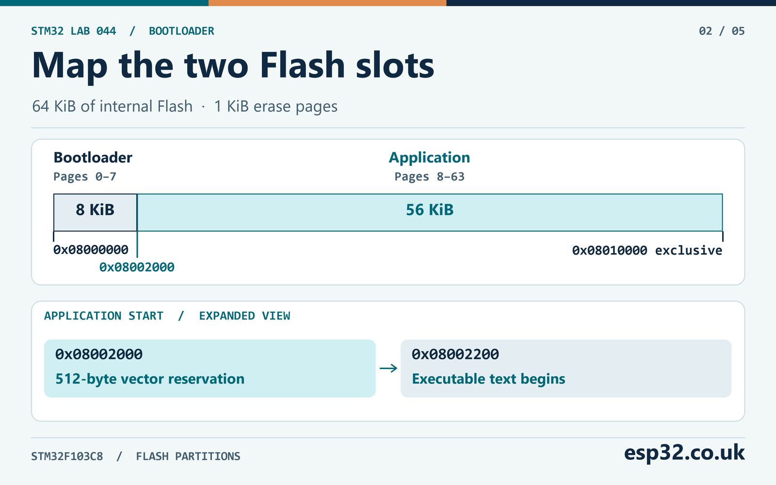
The Flash slots must stay separate because both images are present at the same time. SRAM is reused after the handoff. Both linker scripts can therefore declare the same SRAM region and initialise the stack at its upper boundary, 0x20005000. A descending stack decrements the pointer before using that space. The upper boundary is a valid initial pointer even though the address is one byte past the last SRAM location.
Anything the bootloader leaves in ordinary SRAM can be overwritten by application startup, including the bootloader’s stack frames and debugger variables. If you later need to pass data through the handoff, reserve a specific range in both linkers and exclude it from the application’s normal zeroing and copy regions. Use an agreed record layout with a validity field. The first bench run can rely on the LED and application-owned variables.
When changing the partition, subtract the new application origin from the same exclusive Flash end. For example, a 12 KiB bootloader would leave 52 KiB on this part and move the application origin by four 1 KiB pages. Update the vector validation limits and startup offset at the same time. Budget the bootloader against its slot even if its current image is much smaller. A successful link against the full device capacity would allow growth into the next image.
Use both the erase geometry and the vector alignment when placing a slot. In this lab, 0x2000 ÷ 0x400 = 8 Flash pages and 0x2000 ÷ 0x200 = 16 alignment units. Moving an image by only 512 bytes would keep the vector alignment but put its start halfway through a 1 KiB erase page. An erase that updates the application could then erase the tail of the bootloader on that same page. An offset on an erase boundary keeps those operations separable.
The supplied scripts reserve at least 1 KiB between the end of static SRAM and the initial stack top. That is a link-time minimum for this lab. The space an actual stack needs depends on the deepest call chain, compiler settings and interrupt nesting. A build can fit its Flash slot and still exhaust SRAM when a new application adds large buffers or deep calls. Check the map for static RAM and account for runtime stack and any heap use separately.
Read the first two vector words
The first word of the vector table is a stack value. The second word is a pointer to the application’s reset handler. Read the two words at 0x08002000 and 0x08002004. The addresses of those words are the locations in Flash where the values are stored. The CPU eventually branches to the value read from the second location.
| Address in application slot | Contents | Use |
|---|---|---|
0x08002000 | Initial MSP, typically 0x20005000 | Stack pointer at application entry |
0x08002004 | Reset vector, with bit 0 set | Pointer passed to the Thumb branch |
0x0800203C | SysTick vector | Confirms which handler the tick will use |
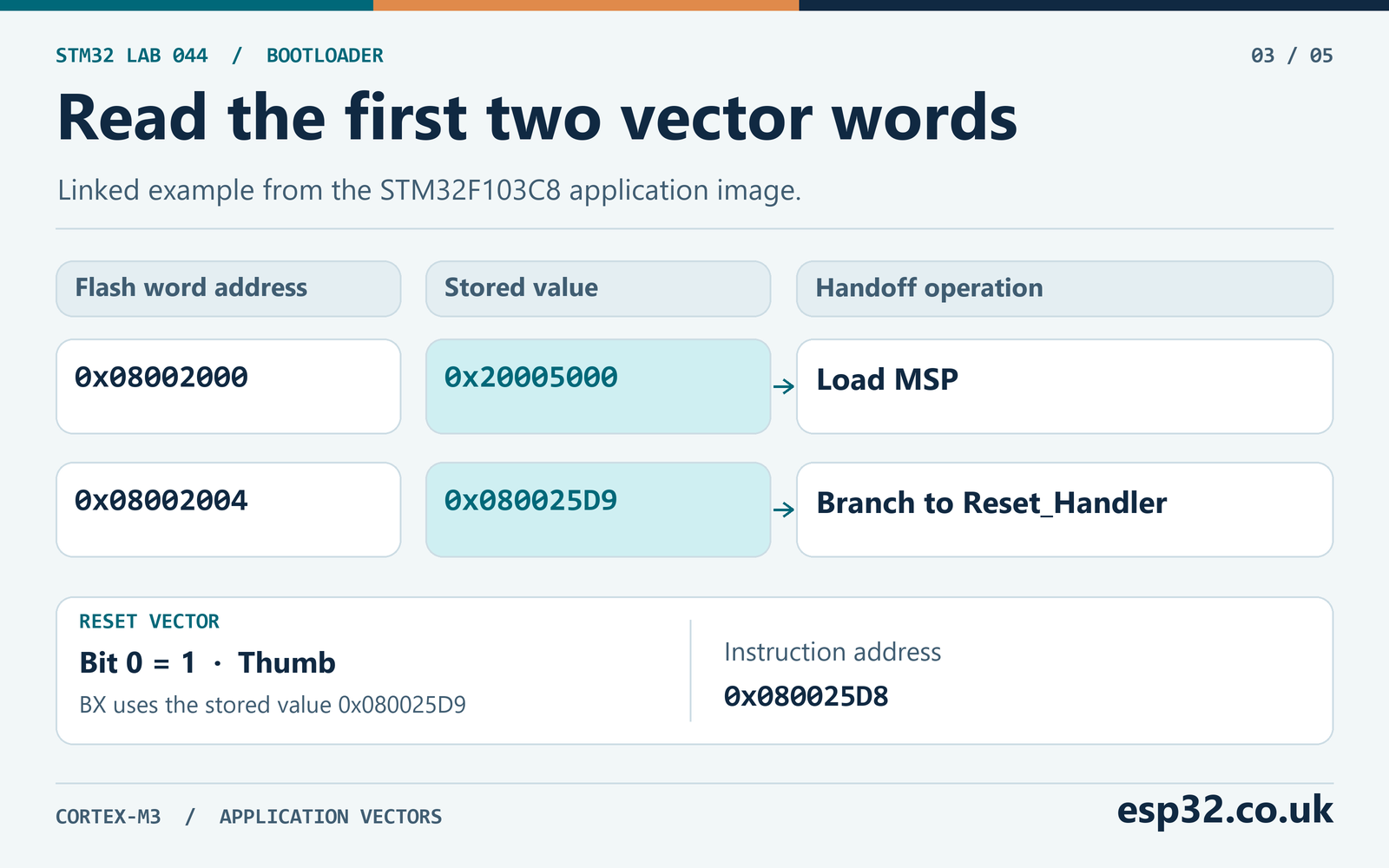
The Cortex-M3 executes Thumb code. A handler address in the vector table has bit 0 set to indicate that state. For bounds checking, strip that bit from a copy of the reset vector. Keep the original odd value for the branch. An example vector of 0x08002201 would select the instruction at 0x08002200. The actual value varies with link order and must be read from the built image. The bytes of 0x20005000 in a little-endian hex view are 00 50 00 20. Use 32-bit word display in the debugger to avoid confusing byte order with a wrong address.
The supplied checker accepts an MSP strictly above the lower SRAM boundary and at or below the upper boundary. It requires eight-byte alignment, matching the stack alignment expected at a public call interface. It rejects an even reset vector and an entry point outside 0x08002200–0x0800FFFF. Excluding the first 512 bytes prevents a plausible-looking pointer into the reserved vector region from passing the check. ST PM0056 Cortex-M3 programming manual · Arm AAPCS32
These tests establish plausibility. An erased vector table normally fails at the first check, because 0xFFFFFFFF lies outside SRAM. An application built for the base of Flash can also fail when copied to the upper slot, because its reset pointer still targets the lower slot. A damaged image could have two plausible words. The checker has no length, checksum or signature metadata to confirm the complete image. For a firmware update path, add image verification before calling the handoff. STM32 hardware CRC32 tutorial
| Initial MSP | Reset vector | Result |
|---|---|---|
0x20005000 | 0x080025D9 | Accepted for the linked fixture |
0xFFFFFFFF | 0xFFFFFFFF | Invalid stack, typical erased slot |
0x20004FFC | 0x080025D9 | Invalid stack alignment |
0x20005000 | 0x080025D8 | Missing Thumb bit |
0x20005000 | 0x08000201 | Entry points into the bootloader |
0x20005000 | 0x08002001 | Entry points into the reserved vector area |
If the same reset vector appears in both slots, inspect each build independently. The expected stack words may be identical because both images use the same RAM. The reset targets should differ because the images occupy different Flash addresses. An application binary built at one origin retains its linked absolute addresses when copied elsewhere. Programming it at a new destination does not recalculate its vectors or the addresses used for startup data.
Link the application at its real address
Create two STM32F103C8 GCC projects with the usual ST startup file for STM32F103xB. Give the outputs distinct names, such as boot.elf and app.elf. The projects need their own main source, linker script and compiled system initialisation. Keep a copy of each generated linker script before changing it. Use the supplied boot.ld and app.ld for this minimal lab, or apply the same region and section changes to your generated scripts. Larger projects may depend on extra sections and symbols supplied by their existing linker script. STM32CubeMX and STM32CubeIDE setup
Set FLASH in the boot project to origin 0x08000000 and length 8K. In the app project use origin 0x08002000 and length 56K. Keep SRAM origin 0x20000000 and length 20K in each. Check the build log or linker command to see which script was actually selected. Changing a file that the active build configuration never uses has no effect on the image.
The supplied app script starts the vector section at the Flash origin and begins text at the origin plus 0x200. The vector section uses KEEP so a link with section garbage collection retains it. The assertion on vector size stops the build if the table exceeds its reservation. The region length stops Flash load sections from growing past the slot. The section layout also places the load copy for initialised data in Flash and its runtime location in SRAM.
MEMORY
{
  FLASH (rx)  : ORIGIN = 0x08002000, LENGTH = 56K
  RAM   (xrw) : ORIGIN = 0x20000000, LENGTH = 20K
}

/* In SECTIONS of the application script */
.isr_vector ORIGIN(FLASH) : { KEEP(*(.isr_vector)) } > FLASH
.text (ORIGIN(FLASH) + 0x200) : { *(.text*) *(.rodata*) } > FLASH
This excerpt shows the placement rules. Keep the startup symbols for copying .data and clearing .bss, along with the project’s other required sections. When adapting a generated script, reserve the vector area before the first executable output section and preserve all of the input sections the rest of the application uses. The full scripts in the package are the ones used to link this lab.
Set the vector address in SystemInit
The bootloader writes VTOR before it branches. The application then executes its own copy of SystemInit(), so check what that copy does to VTOR. In the STM32F1 device template used for the lab, enable USER_VECT_TAB_ADDRESS in both projects. Keep the vector base as FLASH_BASE. Use VECT_TAB_OFFSET = 0x00000000U for the bootloader and 0x00002000U for the application. Keep the SRAM vector option disabled. In versions that define the offset directly in the file, edit that definition. If the template guards it with #if !defined(VECT_TAB_OFFSET), a project compiler definition can supply the offset. Read the version that actually gets compiled. ST STM32F1 CMSIS system template
The offset is relative to FLASH_BASE. Supplying the full address as the offset obscures the relationship and can lead to an invalid relocation when the base changes. The template requires the vector offset to be a multiple of 0x200, and this slot meets that alignment. Make sure SCB->VTOR reads 0x08002000 in the application after SystemInit(). A linked vector table at the correct address cannot help an interrupt if VTOR still points to the lower image.
In the ST GCC startup used here, the reset handler calls SystemInit(), then copies the initialised data from Flash, zeros .bss and runs the C library initialisation before entering main(). Check the startup file from your installed device pack because other startup implementations can order some of those steps differently. Code added to this SystemInit() must account for its position before the normal C data setup. ST STM32F103xB GCC startup
Inspect both ELF files before programming
Run the GNU Arm toolchain’s section and symbol tools on both files. The first output is a memory placement check. The second lets you compare the vector words to the linked handlers.
arm-none-eabi-objdump -h boot.elf
arm-none-eabi-objdump -h app.elf
arm-none-eabi-nm -n app.elf
arm-none-eabi-objdump -s -j .isr_vector app.elf
Look for .isr_vector at 0x08000000 in the boot image and 0x08002000 in the app image. The app text begins at 0x08002200. Check the load address of .data as well as its runtime address. In the linked fixture, the app’s .data runs at 0x20000000 and loads from 0x08002710. Programming only the visible vector and code bytes would leave out those initialisers. The ELF describes the required addresses.
In the same build, the application reset vector is 0x080025D9. Its actual Thumb instruction begins at 0x080025D8. The application SysTick vector is 0x08002201. The stack word is 0x20005000. Your build can move the functions, so compare against its own symbols. A linker tool may display Thumb function symbols at the even instruction address, while the stored vector includes the state bit.
The fixture’s table occupies 268 bytes. The script reserves 512 bytes, leaving 244 bytes of space before the text starts. The table still begins exactly at the slot base. Use the section’s address as well as its size when comparing tool output. A size report sums section sizes and can omit gaps. In this fixture, the application has 1,580 Flash bytes in its sections. The span from slot base through the last data initialiser is 1,824 bytes because it includes that gap.
The same link checks can catch duplicate or weak interrupt definitions. In the app symbol listing, find the linked SysTick_Handler and compare its address with the word at vector offset 0x3C. If the word targets a default handler, check whether the source containing the intended handler was excluded from the build, placed in the boot project or compiled with a different name. The two projects each have a vector table and the application needs its own handler entry.
Prepare the Cortex-M3 before the branch
The loader runs from reset in privileged Thread mode with MSP selected. It checks that context before touching the interrupt controller. IPSR is zero in Thread mode. CONTROL is zero when the core is privileged and using MSP in this lab. BASEPRI and FAULTMASK are clear in the reset-started loader. Calling this code from an interrupt, or after switching to an RTOS task stack, violates the handoff contract. A direct branch from an interrupt handler does not perform exception return or unwind the active exception.
After checking the vectors, the loader masks configurable interrupts, stops SysTick, disables external IRQ enables and clears pending IRQs. It uses the number of interrupt register groups reported by ICTR. It clears the SysTick and PendSV pending bits through ICSR’s dedicated write bits. It then sets VTOR, issues the data and instruction synchronisation barriers, and enters the assembly handoff. This keeps application startup from receiving a normal maskable interrupt while its data and stack are being established. ST PM0056 Cortex-M3 programming manual
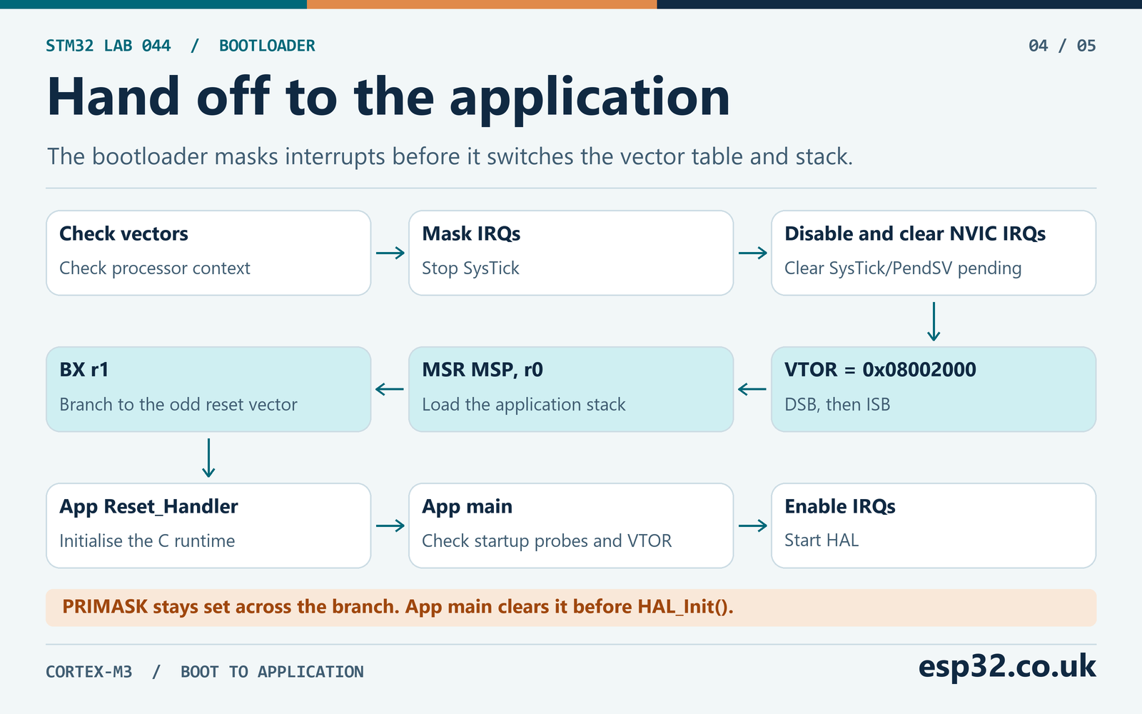
The reset vector and the new stack pointer reach the last routine in r1 and r0, following the Arm calling convention. The GCC naked routine contains only basic assembly. Once it writes MSP, the next instruction branches to the application’s reset handler. Keeping the last two operations in this form avoids a compiler-generated stack access after MSP changes. Check the resulting instructions again if you change compiler, optimisation settings or attributes. Arm AAPCS32 · GCC ARM function attributes
The loader leaves PRIMASK set across the branch. The app clears it once its main function has verified VTOR and the startup data probes. This is a deliberate contract between the supplied images. The standard reset assembly can copy and clear memory while PRIMASK is set. If you add static constructors or early initialisation that wait for interrupts, decide where to enable interrupts before adding that work. If HAL_Delay() is called with PRIMASK still set, SysTick cannot advance the HAL tick and the delay can hang.
The interrupt cleanup shown here is sufficient for the small reset-started loader. If you add peripherals, stop their interrupt sources and DMA requests before disabling and clearing NVIC entries. An asserted peripheral source can pend again. Clocks and hardware already enabled by the loader also carry across the branch. A configured watchdog may keep running. Define which state the app inherits, check whether those resources can be stopped, and use the relevant HAL or register sequence while any needed tick is still available. STM32 watchdog guide · STM32 DMA guide
A hardware reset and a software branch start the next instruction in different ways. A hardware reset reloads the initial stack and reset vector through the selected boot mapping and resets the core state. The branch in this lab explicitly selects the application vectors and stack while using the clock and peripheral state established on the board. If the bootloader sets up a PLL, changes Flash wait states or uses a peripheral, include those settings in the app’s initialisation plan. Also account for any interrupt priority grouping the bootloader changed. The application can set its own grouping when it initialises.
Clearing interrupt enables and pending bits addresses two separate states. Disabling an IRQ prevents delivery and can leave a pending bit set. Clearing a pending bit does not disable the source. SysTick and PendSV use the system control block, which is why the loader clears their pending state separately. PRIMASK masks configurable exceptions. NMI and HardFault can still occur during a transition, so the lab begins from a quiet reset-started configuration and keeps the last handoff short.
Build the bootloader and LED application
Add boot_vectors.c, boot_vectors.h and boot_main.c to the boot project and use boot_main.c as its single main implementation. The boot loader source uses CMSIS core and device headers. It needs the ST startup and system files. Remove any generated main or other sources that would initialise peripherals before this lab’s main function. Keep the hardware reset as the normal entry to the loader.
#ifndef BOOT_VECTORS_H
#define BOOT_VECTORS_H

#include <stdint.h>

#define APP_BASE       UINT32_C(0x08002000)
#define APP_CODE_START UINT32_C(0x08002200)
#define FLASH_END      UINT32_C(0x08010000)
#define RAM_BASE_ADDR  UINT32_C(0x20000000)
#define RAM_END_ADDR   UINT32_C(0x20005000)

typedef enum {
    BOOT_READY, BOOT_BAD_STACK, BOOT_BAD_THUMB, BOOT_BAD_ENTRY, BOOT_BAD_CONTEXT
} BootResult;

BootResult Boot_CheckVectors(uint32_t msp, uint32_t reset_vector);

#endif
#include "boot_vectors.h"
BootResult Boot_CheckVectors(uint32_t msp, uint32_t reset_vector)
{
if (msp <= RAM_BASE_ADDR || msp > RAM_END_ADDR || (msp & 7U) != 0U) {
return BOOT_BAD_STACK;
}
if ((reset_vector & 1U) == 0U) {
return BOOT_BAD_THUMB;
}
uint32_t entry = reset_vector & ~UINT32_C(1);
if (entry < APP_CODE_START || entry >= FLASH_END) {
return BOOT_BAD_ENTRY;
}
return BOOT_READY;
}#include "stm32f1xx.h"
#include "boot_vectors.h"
volatile BootResult boot_result;
static void hold(BootResult result)
{
boot_result = result;
for (;;) {
__NOP();
}
}
__attribute__((naked, noreturn, noinline, noclone))
void Boot_EnterApplication(uint32_t msp __attribute__((unused)),
uint32_t reset_vector __attribute__((unused)))
{
__asm volatile (
"msr msp, r0\n"
"bx r1\n"
);
}
int main(void)
{
const volatile uint32_t *vectors = (const volatile uint32_t *)APP_BASE;
uint32_t msp = vectors[0];
uint32_t reset_vector = vectors[1];
BootResult result = Boot_CheckVectors(msp, reset_vector);
if (result != BOOT_READY) {
hold(result);
}
if (__get_IPSR() != 0U || __get_CONTROL() != 0U ||
__get_BASEPRI() != 0U || __get_FAULTMASK() != 0U) {
hold(BOOT_BAD_CONTEXT);
}
__disable_irq();
SysTick->CTRL = 0U;
SysTick->LOAD = 0U;
SysTick->VAL = 0U;
uint32_t groups = (SCnSCB->ICTR & SCnSCB_ICTR_INTLINESNUM_Msk) + 1U;
for (uint32_t group = 0; group < groups; ++group) {
NVIC->ICER[group] = UINT32_MAX;
NVIC->ICPR[group] = UINT32_MAX;
}
SCB->ICSR = SCB_ICSR_PENDSTCLR_Msk | SCB_ICSR_PENDSVCLR_Msk;
boot_result = BOOT_READY;
SCB->VTOR = APP_BASE;
__DSB();
__ISB();
Boot_EnterApplication(msp, reset_vector);
}In the application project use app_main.c, the shared boot_vectors.h, and the CubeF1 GPIO, RCC, Cortex and HAL support needed for HAL_Init() and the LED. The sample defines SysTick_Handler(). Keep a single definition in the build. If you retain a generated interrupt file that owns this handler, move the two handler statements into that file and remove the definition from app_main.c. Keep the matching time base on SysTick. Use the default 1 ms HAL tick for this run.
#include "stm32f1xx_hal.h"
#include "boot_vectors.h"

volatile uint32_t app_data_probe = 0x41505031U;
volatile uint32_t app_zero_probe;
volatile uint32_t app_ticks;

void SysTick_Handler(void)
{
    HAL_IncTick();
    ++app_ticks;
}

int main(void)
{
    if (SCB->VTOR != APP_BASE || app_data_probe != 0x41505031U || app_zero_probe != 0U) {
        for (;;) {
            __NOP();
        }
    }
    app_zero_probe = 1U;

    __enable_irq();
    if (HAL_Init() != HAL_OK) {
        for (;;) {
            __NOP();
        }
    }
    __HAL_RCC_GPIOC_CLK_ENABLE();
    HAL_GPIO_WritePin(GPIOC, GPIO_PIN_13, GPIO_PIN_SET);
    GPIO_InitTypeDef led = {.Pin = GPIO_PIN_13, .Mode = GPIO_MODE_OUTPUT_PP,
                           .Speed = GPIO_SPEED_FREQ_LOW};
    HAL_GPIO_Init(GPIOC, &led);

    for (;;) {
        HAL_GPIO_TogglePin(GPIOC, GPIO_PIN_13);
        HAL_Delay(250U);
    }
}
The application compares its data marker with 0x41505031 and expects its zero-initialised probe to begin at zero. It sets the latter to one after those checks. If they fail or VTOR is wrong, the sample remains in a debugger-visible loop before enabling interrupts. On success it enables SysTick through HAL and toggles PC13 every 250 ms. Expect four transitions per second, or a full on-off cycle every 500 ms.
Program both images and verify the handoff
Use a dedicated bench board or back up any firmware and data you need from its user Flash. Connect using SWD with BOOT0 low. Load the boot ELF, program and verify it. Then load the application ELF and program and verify the application pages. Select the normal erase for the programmed region and leave full-chip erase off for the second operation. A mass erase after programming the first file removes the loader. Using the ELF preserves the load addresses. If you export raw binaries, explicitly enter the correct base for each file. STM32 SWD flashing guide · ST STM32CubeProgrammer programming and erasing
Read the first two words at both Flash origins back from the target. Each first word should match the stack top configured in its script. The lower reset vector should point into the bootloader slot, and the upper reset vector into the application. Compare the stored words with the ELF you just built. A mismatch at this stage is a programming or file-selection problem. Work on that before inspecting the processor’s handoff sequence.
Reset with the hardware reset line or a debugger reset that starts from the hardware boot path. A debugger may start directly at the executable it downloaded. That would prove the application can execute under the debugger, with little evidence about the real reset path. Set an early breakpoint in the bootloader and a breakpoint at the even address of the application’s reset instruction. On a working run, the bootloader breakpoint is reached first and the application breakpoint follows. Use hardware breakpoints for addresses in Flash.
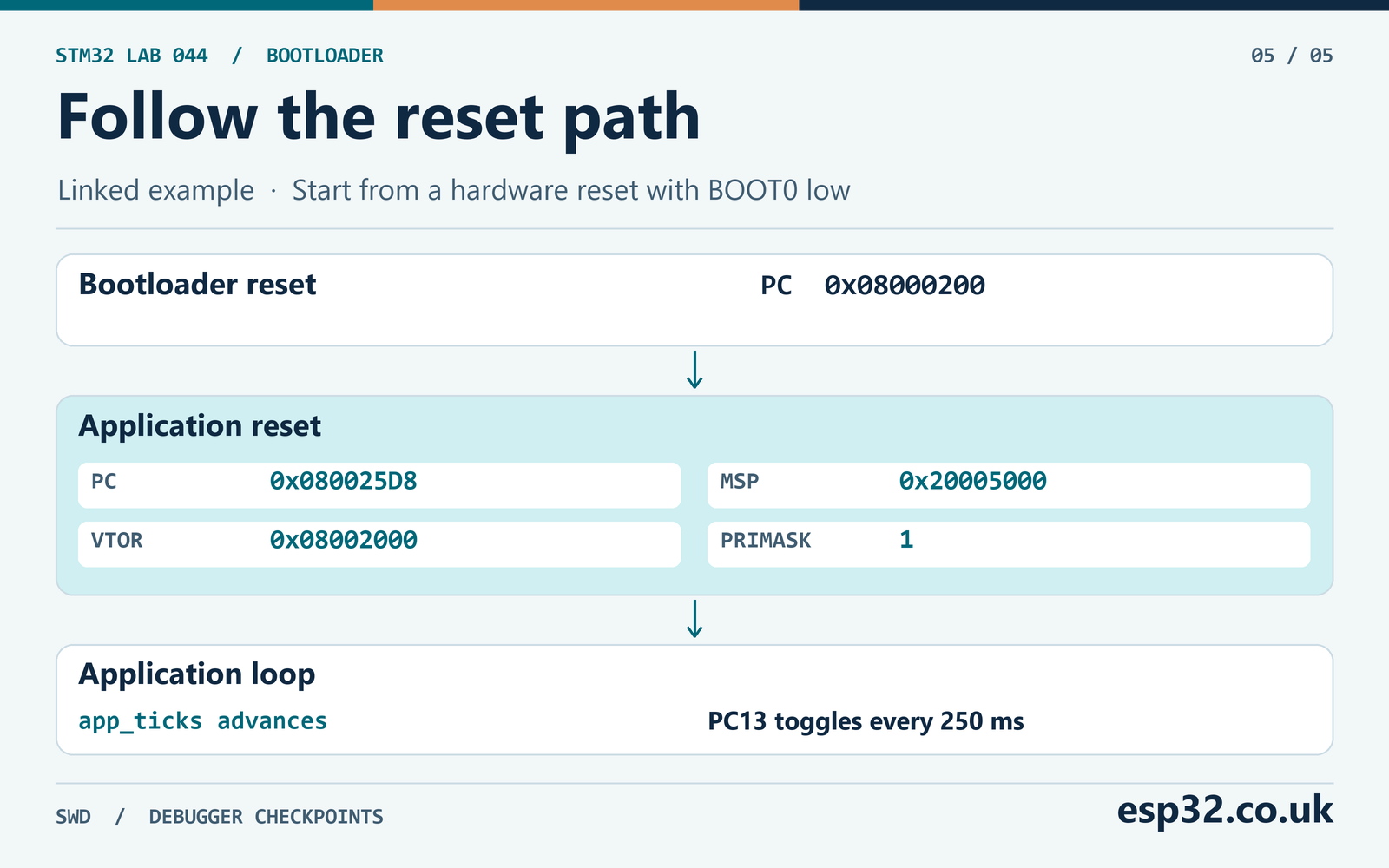
At the application reset breakpoint, inspect PC, MSP, VTOR and PRIMASK. For the example build the PC is 0x080025D8, MSP is 0x20005000, VTOR is 0x08002000 and PRIMASK is one. Stop at the beginning of reset to see the exact initial stack value. Once startup calls functions, their stack use can move MSP down. At application main, check that the initialised marker is present and the zero probe has been set by startup to zero. After the initial checks, the code sets the zero probe to one. After resuming, app_ticks should advance and PC13 should toggle.
| Checkpoint | What to inspect | Expected result |
|---|---|---|
| Target Flash after programming | Words at 0x08000000 and 0x08002000 | Two independently placed vector tables |
| Before the assembly branch | r0, r1 and VTOR | App MSP, original odd reset vector and 0x08002000 |
| First app reset instruction | MSP and PRIMASK | Stack top and interrupts masked |
| App main before its first check | App data marker and zero probe | 0x41505031 and zero |
| App loop | app_ticks and PC13 | 1 ms tick and output transition every 250 ms |
For a final power-on check, let the board boot with the debugger disconnected. The LED should begin blinking after startup. If the board lacks the expected LED connection, use a probe on PC13 or return to the debugger and verify the tick count. Separately test the empty application case on the dedicated board by leaving the application slot unprogrammed. The bootloader should enter its hold loop with BOOT_BAD_STACK. Restoring the verified application should restore the handoff.
Write down which executable the debugger loaded for symbols. A boot-only symbol file can resolve the bootloader breakpoint while showing only numeric addresses in the application. An application symbol file can label the LED loop and handlers. If the debugger supports loading additional symbols without downloading the image, add the application symbols using the linked section addresses. Otherwise use the two numeric breakpoint addresses from the ELF outputs. Keep the original programmed bytes in place between checks so the observation represents the same reset path.
The example’s boot_result is useful while the core is still in the loader. After entering the app, the app’s startup may reuse the same address in SRAM. Watch the boot result at the hold loop or before the final branch. Once the application starts, prefer its marker, tick counter and PC. Those observations belong to memory that the application owns.
Record the current program counter together with any watch value. The boot result starts at zero after reset, so a zero value by itself cannot establish that the loader reached the branch.
Diagnose the first failing stage
| Symptom | Likely place to look |
|---|---|
| Reset never reaches boot main | BOOT0, lower vector words, SWD reset mode or missing boot image |
BOOT_BAD_STACK | Erased slot, wrong programming address, alignment or RAM layout |
BOOT_BAD_THUMB | Even reset vector or invalid vector bytes |
BOOT_BAD_ENTRY | App linked at the wrong origin, reserved range or an out-of-slot target |
| Branch reaches reset and then stops | App startup, initialisers, linker load addresses or VTOR |
| App enters its loop but delay stalls | PRIMASK, SysTick configuration, HAL time base and app handler |
| SysTick reaches the boot default handler | App SystemInit() restored the lower VTOR or app vector symbol is wrong |
| Works under the debugger only | Direct start at the app entry, debugger clock changes or an unexpected reset path |
When the reset vector looks plausible and the CPU faults immediately, compare the stored vector word with the actual instructions at its even address. Read the fault status registers and record the stacked PC where available. A fault during vector lookup and a fault inside the application’s reset handler call for different checks. Also review the last few boot instructions in the disassembly. If the code touches the old C stack after changing MSP, fix the branch routine before chasing GPIO setup.
When app_data_probe has the wrong value, compare the .data load section in Flash with the runtime address in SRAM. The two addresses are expected to differ. An ELF download can place the initialisers correctly while a hand-built binary made by copying only the text section omits them. If the zero probe is nonzero before the application runs its check, inspect the startup’s _sbss and _ebss symbols and make sure the app actually entered its own reset handler.
If the app LED toggles once then stops, look at the counter in the app SysTick handler. If app_ticks advances and the HAL delay still stalls, check whether the handler increments the HAL tick used by that build. A project configured to use a separate HAL timer time base needs that timer and its interrupt path. For the supplied code, keep the default SysTick time base and a single handler definition. The application breakpoint after HAL_Init() helps isolate a clock or tick configuration failure from an LED wiring problem.
If the tick runs but the LED timing is wrong, check the clock value used to configure SysTick. SystemCoreClock must match the actual core clock. The two supplied projects start from the reset clock tree. If you add a different clock configuration, update it through the generated clock code or refresh the core clock value before using it for timing. Check successive PC13 transitions at the pin. The LED’s active polarity can change whether the first interval is lit, while the measured transition interval should remain about 250 ms.
Make one change at a time while diagnosing a handoff. Keep the last pair of verified ELF files so you can return to a known memory map. If a larger application fails, the supplied LED app can isolate the loader and branch from the new application’s peripheral setup. If the LED app also fails, compare both vector tables, the programming addresses and the boot conditions with the earlier run.
Extend the loader after the bench test
A firmware update path needs its own decisions about image length, acceptable Flash range, integrity and recovery. A transport can carry bytes over UART or from external SPI NOR, but the destination must fit entirely in the application slot. Check the declared length and the end calculation before erasing or writing. Compare the programmed bytes with the expected integrity value before using the reset vector. For an environment that needs authenticated updates, choose an appropriate signature and trust model. A plausible vector pair supplies only the entry information used in this tutorial. STM32 UART tutorial · STM32 external SPI NOR lab
An interrupted update can leave the application slot partly programmed. Design a validity check and a way to return to the loader before adding writes. A single-slot system may need to stay in recovery until a complete image arrives. An update scheme with a second image needs enough space for both copies and an explicit selection policy. Work from the actual Flash map. With this 64 KiB device, even the single 56 KiB application slot uses most of the available storage.
When the loader and application must share reset reasons, pin levels or a clock configuration, write down the state each side promises. The application can explicitly reconfigure what it owns. The loader can stop sources it enabled and verify the state before branching. If you choose a reset-based transition with a retained request flag, use the device’s actual reset and retention rules. The debugger procedure in this guide still gives you an independent way to verify both images and their vectors.