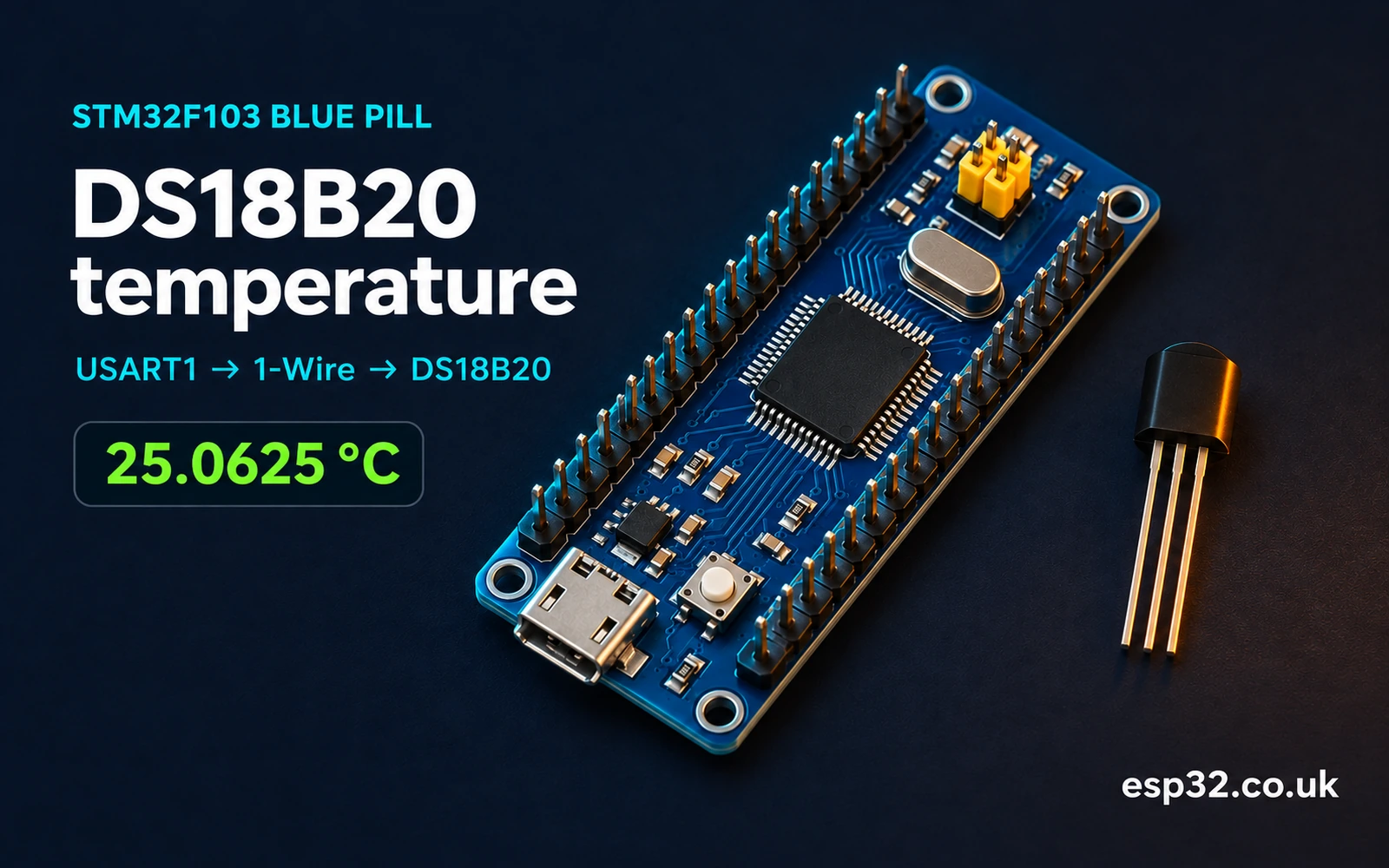
This esp32.co.uk/ guide uses a Blue PillPriceAliExpress price’s USART1 to drive a DS18B20PriceAliExpress price over 1-Wire. The UART supplies the reset pulse and the short and long data slots. A second pin on the same data line lets the receiver see the sensor’s response. The example starts a conversion, waits for the sensor to finish, reads its nine-byte scratchpad and verifies the CRC before updating the temperature.
Use an externally powered 3.3 V DS18B20AliExpress price, a 4.7 kΩ pull-up and the default USART1 pins. PA9 drives the data line through an alternate-function open-drain output and PA10 reads the same line. The code uses 9600 baud for reset and presence detection, then 115200 baud for the data slots. The lab assumes one sensor on a short bus.
Choose the sensor and bus wiring
The DS18B20 measures temperature internally and returns a signed digital result. The STM32Price issues commands and reads that result over a single shared data conductor plus ground. This lab also connects a separate VDD conductor. With external power the sensor can perform its conversion while the data line stays available for read slots. Parasite-powered devices require a strong pull-up during conversion, so use the powered connection shown here. Analog Devices DS18B20 datasheet
Have a Blue Pill with an STM32F103C8, a known DS18B20, a 4.7 kΩ resistor and an SWD programmer. An oscilloscope or logic analyser helps verify both baud rates and the presence pulse. For a bare TO-92 DS18B20 use the datasheet’s package diagram to identify pins 1 through 3. For a waterproof probe or module, use its wiring documentation. Cable colours and connector order depend on the assembly. STM32F103C8 datasheet · Blue Pill pinout
| Blue Pill connection | DS18B20 or bus | Purpose |
|---|---|---|
| 3.3 V | VDD, TO-92 pin 3 | External power |
| GND | GND, TO-92 pin 1 | Common reference |
| PA9, USART1_TX in AF open-drain mode | DQ, TO-92 pin 2 | Drive the line low or release it |
| PA10, USART1_RX as input | Same DQ node | Sample the line as it appears on the wire |
| 4.7 kΩ to 3.3 V | Same DQ node | Restore the high state when drivers release |
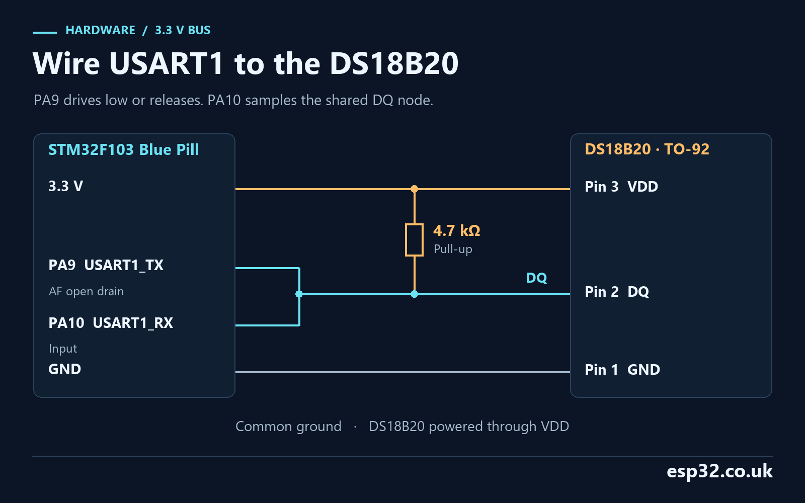
Join PA9 and PA10 at the DQ node only after setting up PA9 as open drain. The open-drain output can pull down and can release the bus, allowing the sensor to pull down during its reply. The pull-up brings the node high when neither device is driving it low. A push-pull UART TX actively drives a high level and can contend with the sensor. Check the generated GPIO mode before connecting the wire.
Measure the bus idle level at DQ with the firmware waiting between readings. It should sit near the sensor supply. When either device pulls it low, the resistor supplies roughly 3.3 V ÷ 4.7 kΩ = 0.70 mA, before accounting for the low-state voltage. A missing pull-up can leave the released line floating. Two module pull-ups in parallel can lower the effective resistance. Check a module’s circuit before adding parts.
Use a short connection for this first run. The released edge rises through the resistor and cable capacitance, while the pull-down edge is driven. For illustration, 4.7 kΩ and 200 pF make a time constant of 0.94 µs. The voltage reaches 70% of the rail after about 1.13 µs in that simple RC model. The actual GPIO threshold and wiring capacitance determine how much margin you have. A cable with ten times the capacitance gives ten times the rise time in the same model. DS18B20 long-wire and multi-sensor guide
If you measure the idle level with a meter, follow up with a scope on DQ during a transaction. The meter averages the reset pulse, the sensor’s reply and the idle period. On the scope, measure the low plateau and the rising edge separately. A low plateau that sits well above ground points to a pull-down or grounding problem. A clean low plateau followed by a slow rise points to a different part of the circuit. Take the same measurements at the sensor connector if the sensor and controller are separated by a cable.
For example, two 4.7 kΩ pull-ups in parallel make 2.35 kΩ. At 3.3 V that increases the ideal low-state current from 0.70 mA to 1.40 mA and halves the simple RC time constant. The measured low voltage still needs to meet the input requirements of both devices. If a breakout board already has a pull-up, check the value and which rail feeds it. Measure resistance with the circuit unpowered and account for other paths through the assembled board.
Configure the STM32 USART and GPIO
Create a CubeF1 project for the STM32F103C8 and retain Serial Wire debug. Enable USART1 with default pin mapping in asynchronous transmit and receive mode. Use eight data bits, no parity and one stop bit. Keep hardware flow control disabled. The USART uses both of its normal pins so it can receive the bus waveform while transmitting. The connection between the pins is at the open-drain DQ node. CubeMX and CubeIDE setup · STM32 USART and HAL guide
| Setting | Value |
|---|---|
| USART | USART1, default pins PA9 and PA10 |
| Mode | Asynchronous TX and RX |
| Format | 8N1, oversampling by 16 |
| Flow control | None |
| PA9 | GPIO_MODE_AF_OD |
| PA10 | Input, using the external DQ pull-up |
| Reset baud | 9600 |
| Slot baud | 115200 |
Inspect the USART MSP initialisation. For PA9, change the generated mode to GPIO_MODE_AF_OD before calling HAL_GPIO_Init(). Preserve that change when regenerating the project. One way is to put a second GPIO initialisation in the MSP user region after the generated block, while the pin is still disconnected from the sensor during first bring-up. Then check the pin on the live board. RM0008 allows the USART TX pin to use alternate-function open drain. ST RM0008 reference manual
USART1 is on APB2. For nominal 8 MHz PCLK2, the baud divisors in the tested HAL are 833 at 9600 and 69 at 115200. Those give nominal rates of approximately 9603.84 and 115942.03 baud, respectively. Actual timing also depends on the oscillator. With 72 MHz PCLK2 the divisors are 7500 and 625, giving the target rates at the nominal clock. If the waveform differs materially, check PCLK2, the baud register and the actual oscillator before changing the protocol.
The module owns USART1 for the complete conversion and scratchpad exchange. Keep UART interrupt and DMA reception disabled on that instance. Avoid using the same USART for a console or sharing its pins with an active serial adapter. Use SWD watch variables for the first test. A background read could remove the one UART receive byte that the 1-Wire routine expects to decode.
Check the GPIO setting after both baud rates have run. In an STM32F103 debugger, PA9 occupies the second four-bit field in GPIOA_CRH and PA10 occupies the third. PA9’s CNF bits should select alternate-function open drain and its MODE bits should select an output speed. PA10’s MODE bits should select input. This can catch an initialisation path that runs after your intended configuration. Record the APB2 clock and USART1_BRR at both speeds alongside a capture so you can distinguish a clock configuration issue from an electrical one.
Use the UART start bit to make each 1-Wire slot
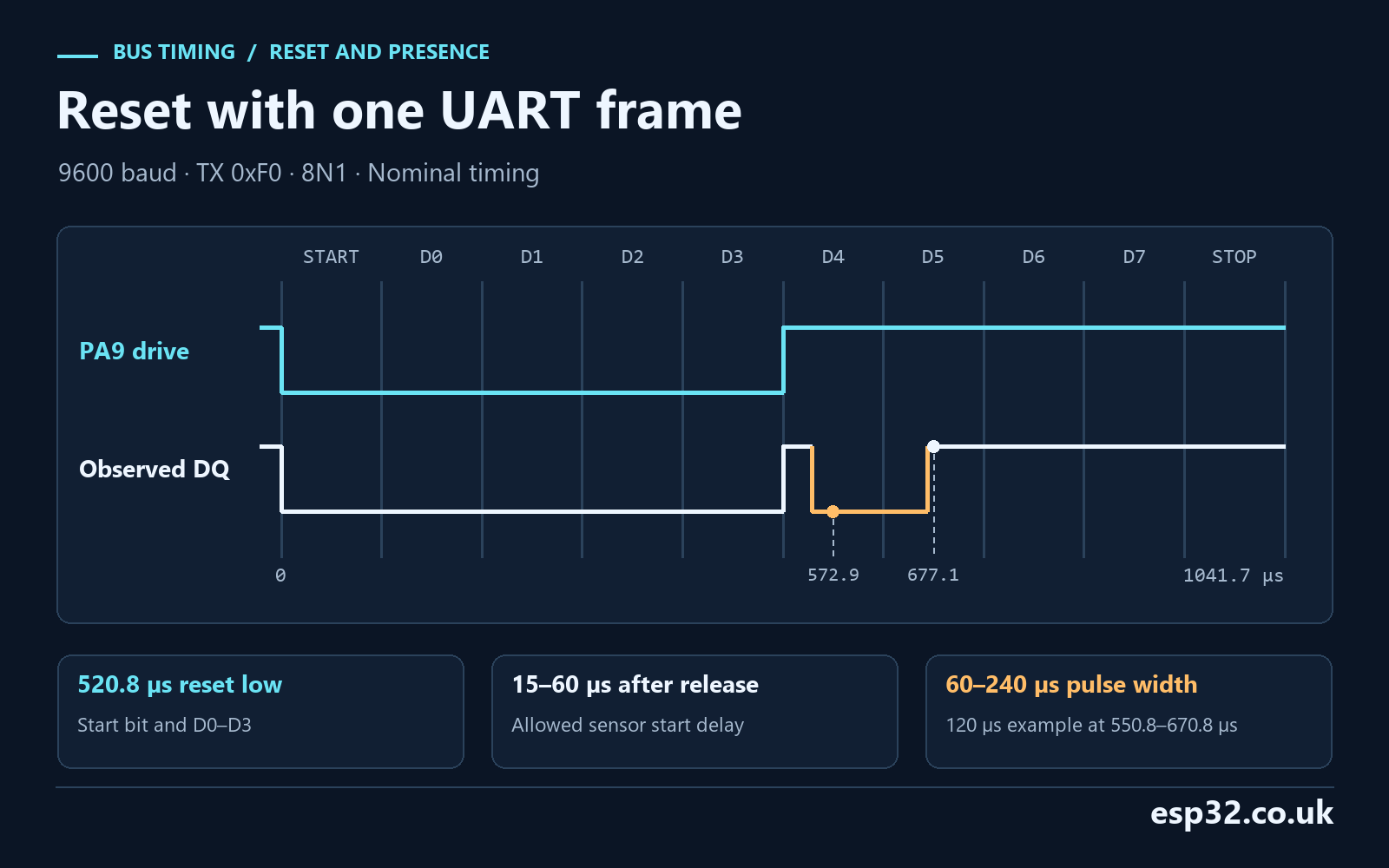
A UART frame in 8N1 starts low. It then sends eight data bits in least-significant-bit order and finishes with one high stop bit. At 9600 baud, writing 0xF0 produces a low start bit and four low data bits. The result is five low bit periods, approximately 520.833 µs. That satisfies the DS18B20 standard-speed reset low requirement of at least 480 µs. The four high data positions and the stop bit then release the line for approximately the same duration.
During the released interval the sensor can assert its presence pulse. The DS18B20 waits 15–60 µs after detecting the release and holds the bus low for 60–240 µs. The receiving UART samples DQ during that same frame, so the presence pulse can turn one or more of the high bits into zeroes. The exact received value varies with presence timing and bus rise time. An unchanged F0 indicates that this exchange detected no presence. The lab also requires the four low data bits and the final high data bit to have their expected levels. A bad stop bit is reported as a UART fault. Analog Devices application note on using a UART as a 1-Wire master
Once presence is detected, switch USART1 to 115200 baud after the reset frame has completed. A 115200-baud bit lasts about 8.681 µs at the nominal rate. Writing FF drives the line low for the start bit and releases it for the remaining nine periods. Writing 00 keeps the line low for the start bit and all eight data bits, about 78.125 µs, then releases it for the stop bit. The full UART frame takes about 86.806 µs, including recovery time while the line is released.
| Operation | UART TX byte | Nominal low pulse | Interpretation |
|---|---|---|---|
| Reset at 9600 | F0 | 520.833 µs | Look for presence in the released part |
| Write one at 115200 | FF | 8.681 µs | Sensor sees a short low pulse |
| Write zero at 115200 | 00 | 78.125 µs | Sensor sees a long low pulse |
| Read at 115200 | FF | 8.681 µs from host | Unchanged FF is one. Other valid echoes represent zero |
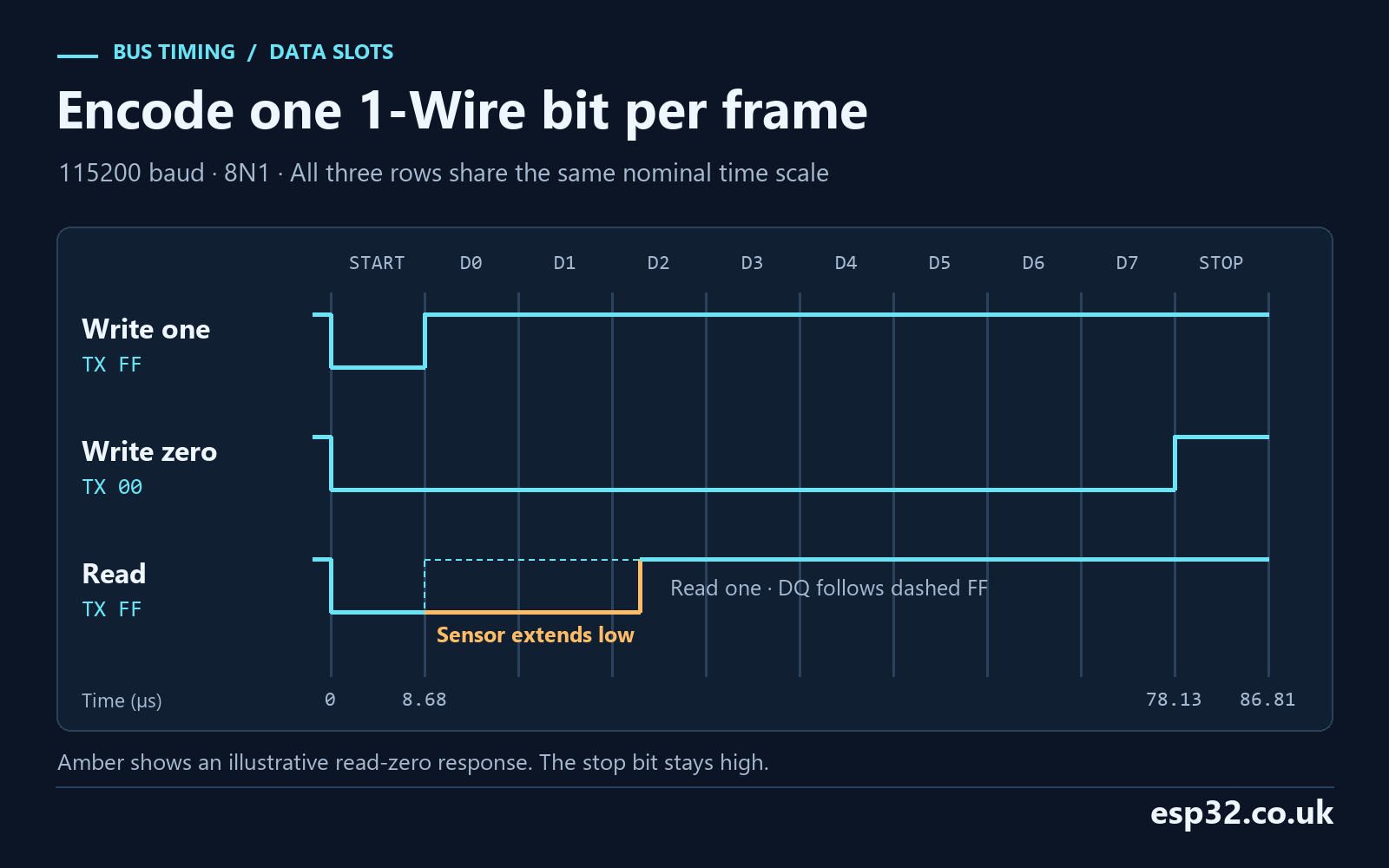
For a read, the sensor can extend the low interval after the host releases the line. In a healthy read-one slot the UART receives all eight data bits as high. In a read-zero slot one or more of those bits is low. The application note uses the complete received byte to distinguish the two cases. Do not expect one fixed byte for every read zero. The UART was designed for serial data with evenly spaced bit boundaries, while the 1-Wire response can change during one of those bit windows.
The DS18B20 specifies a standard-speed read timing window. The UART method depends on the transmitter releasing early enough and the bus reaching a valid high before the receiver samples a read one. On a scope, inspect the low interval and the rise at the sensor end. For comparison, the nominal centre of the first UART data bit lies about 13.02 µs from the start of the slot. The actual sample positions depend on the UART and clock. If high bits are consistently misread at the bench, check the electrical timing rather than assigning another value to a good read-one echo.
The timing thresholds explain why these two baud rates work together. The datasheet gives standard-speed write slots a duration of 60–120 µs and requires at least 1 µs of recovery. The host’s short low pulse satisfies the 1–15 µs write-one requirement. The long low pulse exceeds the 60 µs write-zero minimum and still leaves a full stop bit released. At nominal 8 MHz PCLK2 the small baud error changes the fast short and long pulses to about 8.625 and 77.625 µs. Check the pulse widths with the GPIO configuration and oscillator you actually use.
The slow reset exchange has a different sampling problem. At nominal 9600 baud the bus is released about 520.8 µs from the start, and the last data bit is sampled around 885.4 µs. The longest specified presence delay and pulse together end about 300 µs after the release at the sensor. On the short bench connection, the last data sample should therefore have returned high. The receiver can see an intentional edge near one of its sampling points during presence or a read zero. The routine rejects framing and overrun errors, checks echoes on write slots and uses the scratchpad CRC to verify the assembled data.
The UART samples the first two released data bits about 52 and 156 µs after release. A valid presence pulse that starts 60 µs after release and lasts 60 µs can fall between those samples. If the firmware reports DS_ABSENT while the scope shows a valid pulse, check that pulse against the UART sample positions. This UART lab has that detection limit. For a design that must detect every legal presence pulse, use a dedicated 1-Wire master or time the presence measurement independently, for example with a timer and GPIO edge capture.
Start the conversion before reading the scratchpad
A reading is two 1-Wire transactions with a wait between them. The first selects the sensor and starts conversion. The second selects it again and reads the scratchpad. Each selection starts with a reset and a presence check. The second reset gets the device ready for the next ROM command and is issued only after the conversion has finished.
| Phase | 1-Wire bytes or slots | Result |
|---|---|---|
| First selection | Reset and presence, then CC | Skip ROM on the single-device bus |
| Convert | 44 | Start temperature conversion |
| Wait | Read slots | Zero while busy, one when ready with external power |
| Second selection | Reset and presence, then CC | Select the same single sensor again |
| Read | BE, then 72 read slots | Receive the nine scratchpad bytes |
| Decode | CRC, configuration and signed temperature | Accept a complete valid result |
Each byte on the 1-Wire bus is sent least significant bit first. For example, 0x44 becomes bits 0 0 1 0 0 0 1 0. The code emits a separate UART frame for every one of those bits. The UART frames and the DS18B20 command bytes are different layers. A logic analyser decoding UART will show the repeated FF and 00 tokens at 115200 baud. A 1-Wire decoder can instead group the slots into CC, 44 and the other device commands. Configure the decoder for the layer you want to examine.
Skip ROM is suitable when exactly one DS18B20 is connected. With several devices, more than one sensor could drive the read slots, and the open-drain bus would combine their responses. Use the ROM Search procedure to enumerate devices and Match ROM to address one device before reading. A broadcast conversion can be useful in a multi-device design, but the lab’s read sequence must be changed before several devices share the line.
| DS18B20 resolution | Maximum conversion time | Temperature step |
|---|---|---|
| 9-bit | 93.75 ms | 0.5 °C |
| 10-bit | 187.5 ms | 0.25 °C |
| 11-bit | 375 ms | 0.125 °C |
| 12-bit | 750 ms | 0.0625 °C |
The lab sends a read slot about every five milliseconds during conversion and gives the sensor an 800 ms budget for busy responses. A successful poll ends the wait as soon as firmware detects completion. The exact wall time also includes the poll slot, HAL scheduling and the transaction overhead. That budget covers the 750 ms datasheet maximum at 12-bit resolution with room for polling. The rest of the function adds reset, command and scratchpad time outside the wait. This is a blocking lab call, so take its duration into account before calling it from an application with other deadlines.
External power is essential to this polling method. A parasite-powered device stores energy from the data line and needs a strong pull-up during conversion. That changes when the bus can be driven or read and requires different hardware and timing. Even if a probe replies to reset with VDD disconnected, that reply does not prove the probe will complete a conversion using this circuit.
Verify all nine scratchpad bytes
The read returns temperature low byte, temperature high byte, two alarm threshold bytes, a configuration byte, three reserved bytes and a CRC byte. Include the reserved bytes in the CRC calculation exactly as received. Read nine bytes even if your application uses only the first two. Truncating the read or calculating over just the temperature loses the ability to detect an error elsewhere in the exchange.
| Byte index | Meaning | Worked positive example |
|---|---|---|
| 0 | Temperature LSB | 91 |
| 1 | Temperature MSB | 01 |
| 2 | Alarm high | 4B |
| 3 | Alarm low | 46 |
| 4 | Configuration | 7F |
| 5–7 | Reserved | FF 0C 10 |
| 8 | CRC-8 | 70 |
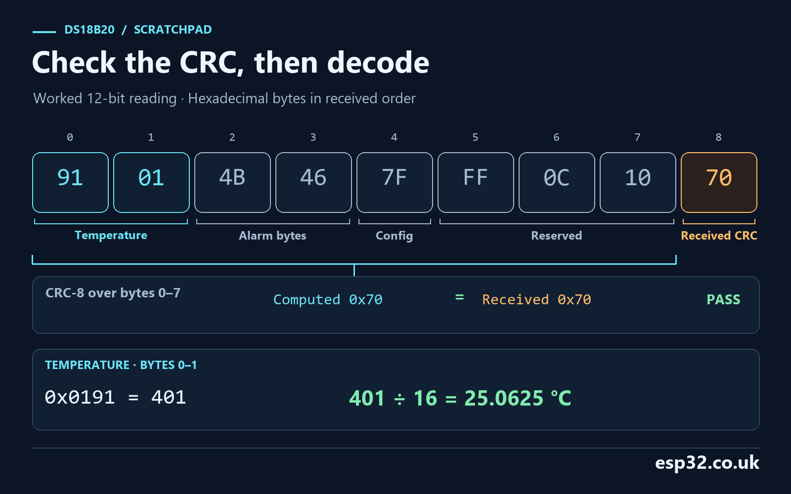
The DS18B20 uses the polynomial x^8 + x^5 + x^4 + 1. For the reflected, right-shifting implementation below the feedback byte is 0x8C, and the starting value is zero. Calculate over bytes 0–7 and compare with byte 8. As a separate software check, the ASCII bytes for 123456789 give 0xA1. A pass confirms the received bytes agree with the transmitted CRC. It does not prove the bus wiring is robust at every temperature or cable length. DS18B20 scratchpad and CRC description
After the CRC matches, form a 16-bit pattern from the low and high bytes. The temperature is signed two’s complement in units of one sixteenth of a degree Celsius. At lower resolutions, some low bits are undefined and should be masked. The driver reads resolution from configuration bits 6 and 5, clears the relevant low bits, then converts the sign and checks the sensor’s specified range of −55 °C to +125 °C. It publishes the output only after all checks pass.
| Full scratchpad example | Temperature word after masking | Result |
|---|---|---|
91 01 4B 46 7F FF 0C 10 70 | 0x0191 | 401 ÷ 16 = 25.0625 °C |
5E FF 4B 46 7F FF 0C 10 6A | 0xFF5E | −162 ÷ 16 = −10.125 °C |
93 01 4B 46 1F FF 0C 10 66 | 0x0190 | 400 ÷ 16 = 25.0 °C at 9-bit resolution |
The configuration is checked for the DS18B20’s fixed bit pattern as well as the resolution bits. A return of all zeros can pass the zero-seeded CRC check, yet it fails this configuration check. A plausible temperature and a valid CRC are still only two parts of the result. Confirm that the host actually ran Convert T before interpreting a power-up scratchpad. The power-up temperature word 0x0550 represents 85 °C. That value can also be a real measurement, so a blanket filter for 85 °C would discard valid data. Verify the conversion sequence and completion slot instead.
Apply the resolution mask to the assembled unsigned word before interpreting its sign. At 9-bit resolution, clear bits 2 through 0 with 0xFFF8. At 10-bit resolution, clear bits 1 and 0 with 0xFFFC. At 11-bit resolution, clear bit 0 with 0xFFFE. Keep all bits at 12-bit resolution. The worked 9-bit example changes from 0x0193 to 0x0190, so the undefined low bits never appear as a false fraction. Calculate the CRC on the original bytes before any masking. The device included those original bits when it calculated the transmitted CRC.
To test the error path in software, take the positive example and change its first byte from 91 to 90 while keeping the received CRC byte 70. The edited temperature is plausible, but the CRC no longer matches. Initialise the caller’s output to a known value before invoking the decoder with the edited buffer. Expect DS_CRC and check that the output retains that value. Then pass the original buffer and confirm it updates to 401. This checks that failure handling protects the last valid sample even when the corrupted value looks realistic.
Add the STM32 HAL module
Copy the supplied header and C file into the CubeF1 project. The module changes the baud rate by updating the UART handle and calling HAL_UART_Init() when no frame is active. The generated GPIO and USART clock setup must already be in place. The blocking HAL transmit waits for the final stop bit, while the enabled receiver samples the same line. Read the one received byte before starting the next slot. ST CubeF1 UART HAL v1.1.10
#ifndef DS18B20_LAB_H
#define DS18B20_LAB_H

#include "stm32f1xx_hal.h"

typedef enum { DS_OK, DS_ARG, DS_UART, DS_ABSENT, DS_BUS, DS_TIMEOUT, DS_CRC, DS_DATA } DsResult;

uint8_t Ds_Crc8(const uint8_t *bytes, uint16_t length);
DsResult Ds_Decode(const uint8_t scratch[9], int16_t *sixteenths);
DsResult Ds_ReadTemperature(UART_HandleTypeDef *uart, int16_t *sixteenths);

#endif
#include "ds18b20_lab.h"
uint8_t Ds_Crc8(const uint8_t *bytes, uint16_t length)
{
uint8_t crc = 0;
for (uint16_t i = 0; i < length; ++i) {
crc ^= bytes[i];
for (unsigned bit = 0; bit < 8; ++bit) {
crc = (uint8_t)((crc >> 1) ^ ((crc & 1U) ? 0x8CU : 0U));
}
}
return crc;
}
DsResult Ds_Decode(const uint8_t scratch[9], int16_t *sixteenths)
{
if (!scratch || !sixteenths) {
return DS_ARG;
}
if (Ds_Crc8(scratch, 8) != scratch[8]) {
return DS_CRC;
}
uint8_t config = scratch[4];
if ((config & 0x9FU) != 0x1FU) {
return DS_DATA;
}
unsigned unused = 3U - ((config >> 5) & 3U);
uint32_t word = ((uint32_t)scratch[1] << 8) | scratch[0];
word &= ~((1UL << unused) - 1UL);
int32_t value = (int32_t)(word ^ 0x8000U) - 0x8000;
if (value < -880 || value > 2000) {
return DS_DATA;
}
*sixteenths = (int16_t)value;
return DS_OK;
}
static DsResult exchange(UART_HandleTypeDef *uart, uint8_t tx, uint8_t *rx)
{
const uint32_t errors = USART_SR_FE | USART_SR_ORE;
(void)uart->Instance->SR;
(void)uart->Instance->DR;
if (HAL_UART_Transmit(uart, &tx, 1, 10) != HAL_OK) {
return DS_UART;
}
if (uart->Instance->SR & errors) {
(void)uart->Instance->DR;
return DS_UART;
}
return HAL_UART_Receive(uart, rx, 1, 10) == HAL_OK ? DS_OK : DS_UART;
}
static DsResult select_sensor(UART_HandleTypeDef *uart)
{
uint8_t rx;
uart->Init.BaudRate = 9600;
if (HAL_UART_Init(uart) != HAL_OK) {
return DS_UART;
}
DsResult result = exchange(uart, 0xF0, &rx);
if (result != DS_OK) {
return result;
}
if (rx == 0xF0U) {
return DS_ABSENT;
}
if ((rx & 0x8FU) != 0x80U) {
return DS_BUS;
}
uart->Init.BaudRate = 115200;
return HAL_UART_Init(uart) == HAL_OK ? DS_OK : DS_UART;
}
static DsResult write_byte(UART_HandleTypeDef *uart, uint8_t value)
{
for (unsigned i = 0; i < 8; ++i) {
uint8_t tx = (value & 1U) ? 0xFFU : 0;
uint8_t rx;
DsResult result = exchange(uart, tx, &rx);
if (result != DS_OK) {
return result;
}
if (rx != tx) {
return DS_BUS;
}
value >>= 1;
}
return DS_OK;
}
static DsResult read_bit(UART_HandleTypeDef *uart, uint8_t *bit)
{
uint8_t rx;
DsResult result = exchange(uart, 0xFF, &rx);
if (result == DS_OK) {
*bit = rx == 0xFFU;
}
return result;
}
static DsResult command(UART_HandleTypeDef *uart, uint8_t opcode)
{
DsResult result = select_sensor(uart);
if (result == DS_OK) {
result = write_byte(uart, 0xCC);
}
return result == DS_OK ? write_byte(uart, opcode) : result;
}
DsResult Ds_ReadTemperature(UART_HandleTypeDef *uart, int16_t *sixteenths)
{
if (!uart || !sixteenths || uart->Instance != USART1 ||
uart->Init.WordLength != UART_WORDLENGTH_8B || uart->Init.StopBits != UART_STOPBITS_1 ||
uart->Init.Parity != UART_PARITY_NONE || uart->Init.Mode != UART_MODE_TX_RX ||
uart->Init.HwFlowCtl != UART_HWCONTROL_NONE) {
return DS_ARG;
}
DsResult result = command(uart, 0x44);
if (result != DS_OK) {
return result;
}
uint32_t start = HAL_GetTick();
for (;;) {
uint8_t ready;
result = read_bit(uart, &ready);
if (result != DS_OK) {
return result;
}
if (ready) {
break;
}
if ((uint32_t)(HAL_GetTick() - start) >= 800U) {
return DS_TIMEOUT;
}
HAL_Delay(5);
}
result = command(uart, 0xBE);
if (result != DS_OK) {
return result;
}
uint8_t scratch[9] = {0};
for (unsigned byte = 0; byte < sizeof scratch; ++byte) {
for (unsigned bit = 0; bit < 8; ++bit) {
uint8_t value;
result = read_bit(uart, &value);
if (result != DS_OK) {
return result;
}
scratch[byte] |= (uint8_t)(value << bit);
}
}
return Ds_Decode(scratch, sixteenths);
}On STM32F1 the status-then-data read clears a stale receive indication and error flags. The driver drains a stale byte before each slot because it owns the UART. If another part of the application reads DR at the same time, it could consume the live echo and cause an apparent timeout. The read and write functions keep the next slot from starting until the previous exchange finishes. Interrupt activity between slots can stretch the released interval, but the UART supplies the low pulse without relying on a C delay loop.
The code handles a typical single DS18B20 bus and makes a few explicit checks that simplify diagnosis. It accepts a presence echo with the expected low and final high bits, verifies the complete echo during command writes, and interprets valid read echoes according to the UART method. A malformed presence echo or corrupted command write causes an immediate error. The next foreground call starts over with a fresh reset. If you observe intermittent false echoes, capture the line and determine whether the high state is reaching the GPIO input in time.
Bring up the sensor on the bench
Program the board over SWD and keep the sensor close to the MCU. Use a stable 3.3 V supply with common ground. Check PA9 mode before joining it to DQ and PA10. With a debugger, confirm that the first call returns a status and that the watch values change only after a valid read. The example below uses milli-degrees Celsius for convenient display while retaining the exact signed value in sixteenths. Flash an STM32 with ST-Link and STM32CubeProgrammer
Put the include and watch variables at file scope, and insert the remaining lines after GPIO and USART1 initialisation in the generated project. Keep the default HAL tick running. The short initial delay is bench margin before the first transaction. The one-second delay occurs after each call, so the start-to-start sampling period also includes conversion and bus time.
#include "ds18b20_lab.h"
volatile DsResult ds_result;
volatile int16_t ds_sixteenths;
volatile int32_t ds_millic;
volatile uint32_t ds_good_reads;

/* After the generated initialisation */
HAL_Delay(100U);
for (;;) {
    int16_t raw;
    ds_result = Ds_ReadTemperature(&huart1, &raw);
    if (ds_result == DS_OK) {
        ds_sixteenths = raw;
        ds_millic = (int32_t)raw * 1000 / 16;
        ++ds_good_reads;
    }
    HAL_Delay(1000U);
}
The integer calculation truncates towards zero. The exact value 25.0625 °C appears as 25,062 milli-degrees and the exact value −10.125 °C appears as −10,125. Keeping the signed raw value avoids losing the fractional half milli-degree. If your display needs a fixed number of decimals, choose a rounding rule at the display boundary and apply it to both signs. The DS18B20’s resolution describes the numerical step. It does not establish that the physical measurement is accurate to one step.
Let the sensor settle to room temperature and watch several successful samples. Warm the package gently with a finger and look for a rise across successive readings. The response depends on the package and contact. A waterproof probe can respond more slowly than a bare TO-92. Use the variation as a functional test and compare against a suitable reference if you need calibration evidence.
Disconnect the sensor data lead with the system powered down, keeping the UART loopback and pull-up wired. Power up again. The reset echo should now be F0 and the function should return DS_ABSENT. The last good value persists across transient failures within one running session. A power cycle reinitialises the watch variables. Keep a valid-reading count or timestamp alongside the last value if other code consumes it.
Read the capture in the right order
Trigger on the falling edge of the reset pulse. The first low interval should be close to 521 µs. After the release, look for a separate low pulse from the sensor. Inspect that interval directly before relying on the received byte. A slow rise can merge the host’s pulse and the sensor’s presence at the logic analyser threshold, even when both devices are pulling the line low at the expected times.
Next use a second capture around the fast slots. Write zeros are low for about 78 µs, and write ones release after about 8.7 µs. After the first two command bytes, the conversion polls are short host pulses. Early polls can be extended by the sensor and the completion poll should show a released high interval. The next long reset separates the conversion transaction from the scratchpad read. The expected order is reset, CC, 44, polls, reset, CC, BE, then 72 read slots.
Count the fast slot frames if the scratchpad seems shifted. The two selection and command groups each require 16 fast slots. The scratchpad needs 72, and completion adds at least one poll. With one poll this is 105 fast frames, roughly 9.11 ms of UART clocking at nominal 115200 baud. The two reset frames add about 2.08 ms of UART time. The conversion interval and software gaps dominate the elapsed transaction time at 12-bit resolution.
The receive logic treats a read echo as zero if any data bit is low. A slow rising bus can therefore turn a read one into a zero even if the peripheral’s stop bit remains valid. If write-one echoes also fail, compare the DQ waveform at both ends of the wire and inspect the released voltage before the UART samples. Check that the sensor has its own VDD connection and that only PA9, PA10 and DQ are tied to the node.
| Status or symptom | First place to check |
|---|---|
DS_ARG | USART1 handle and 8N1 transmit/receive configuration |
DS_ABSENT | Sensor power, DQ continuity and the presence pulse |
DS_BUS | Reset echo shape, open-drain GPIO, pull-up and write echoes |
DS_UART | Framing or overrun, HAL status, UART clocks and another reader on USART1 |
DS_TIMEOUT | External sensor power, Convert T and conversion poll waveform |
DS_CRC | All nine bytes, slot order and rise time |
DS_DATA | CRC passed but configuration or temperature range failed |
| Stale 85 °C | Verify that a conversion was started and completed before the read |
If the sensor sometimes gives a valid CRC and sometimes fails, keep the failed reads separate from good samples. Record the status counts before adding filters or retries. An application that logs only the last good temperature can hide a bus that has stopped reporting. A timestamp and the latest status show both the previous valid value and the time since the last success. Retry only after a fresh reset, as the lab does on its next call.
If the conversion polls always look busy, check the first command group at the protocol layer before widening the timeout. Decode the eight slots after CC and compare them with the LSB-first representation of 44. Then check that each poll begins with the short host pulse and that the release reaches a usable high level whenever the sensor lets go. A correctly received command with a clean poll waveform gives you a basis for comparing the elapsed conversion time with the resolution setting.
Extend the measurement without losing visibility
In a periodic controller, start a conversion and let other work run before returning to read the scratchpad. Keep the state for the selected sensor, the start time and the completion deadline. A nonblocking design can poll from a scheduled task and leave the fast exchange in one bus owner. Several tasks attempting their own resets or commands can interrupt an in-progress transaction. Protect the complete protocol sequence if multiple consumers share one physical bus.
For several sensors, capture the ROM identifiers during discovery and keep them with the measurement records. A ROM identifier and the scratchpad CRC answer different questions. The identifier lets you select the intended device and label its data. The scratchpad check guards the bytes returned by the selected device. A multi-sensor installation also needs an electrical check at its longest branch, since adding cables and connectors can reduce the margin on the released edge. The short-bus waveform in this guide is a baseline for that comparison.
Store the units explicitly when sending data to another controller or logger. The signed value in sixteenths travels conveniently in two bytes, but the receiver needs an agreed byte order and a valid-reading indicator. Include a sensor identifier if the application can later grow beyond one sensor. A graph or control loop should know whether a value is current and valid even when a previous temperature is still available.
Can the same UART print the result?
The peripheral and pins in this example are part of the 1-Wire bus. Sending text through USART1 would produce unintended slots and could disrupt the sensor. Use SWD watch variables, another UART or another application interface for reporting. If you switch roles in a larger design, arrange a clear hardware and software boundary so a serial console cannot drive the DQ line.
Can I increase the cable length by lowering the baud rate?
These baud rates encode the physical pulse widths. Lowering the fast rate changes the low time and the length of each slot, which can violate the 1-Wire limits. Measure the rise time and validate the pull-up, cable and topology before changing the timing. If a different drive circuit or a dedicated 1-Wire bridge is appropriate for the installation, retest the conversion and scratchpad checks on that hardware.