Quick Summary (TL;DR):
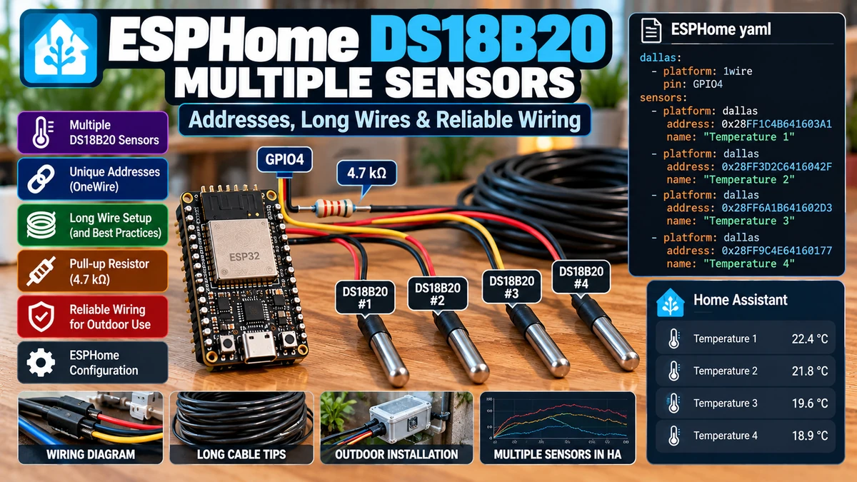
The DS18B20AliExpress price is one of the best sensors for measuring several temperatures with one ESP32AliExpress price because every probe has a unique 64-bit 1-Wire address and multiple devices can share a single DATA GPIO. The hardware looks deceptively simple, but multiple sensors and long cables expose the weaknesses of bad 1-Wire wiring very quickly. For a reliable ESPHome installation, use three-wire powered mode whenever possible, place an external pull-up resistor near the ESP32AliExpress price/master, prefer a linear/daisy-chain bus with short branches rather than a large unswitched star, use twisted-pair cable for long runs, and assign sensors by address rather than index. Current ESPHome uses the top-level one_wire: component plus platform: dallas_temp; the old dallas: / platform: dallas syntax was removed in ESPHome 2024.6. A typical short bus works well with the standard 4.7 kΩ pull-up to 3.3 V. On a longer/heavier bus, the correct resistor is not a magic fixed number: cable capacitance, topology, number of probes and supply voltage all affect rise time. Values around 3.3 kΩ or 2.2 kΩ can sometimes improve a marginal bus, but simply lowering the resistor is not a substitute for good topology. For very long or difficult networks, use an active 1-Wire master such as a DS2482/DS2484-class bridge rather than forcing an ESP32AliExpress price GPIO to drive a huge network. If you see devices randomly disappearing, CRC/checksum warnings, 85°C readings, -127°C-style invalid readings in other libraries, or sensors becoming unavailable only when several probes are attached, suspect the bus wiring/power before blaming Home Assistant.
Materials You’ll Need
| Item | Why you need it |
|---|---|
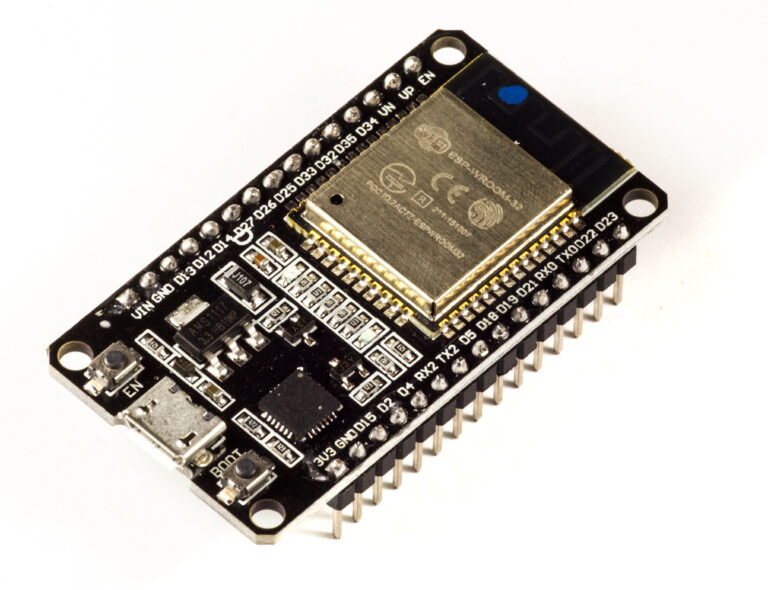
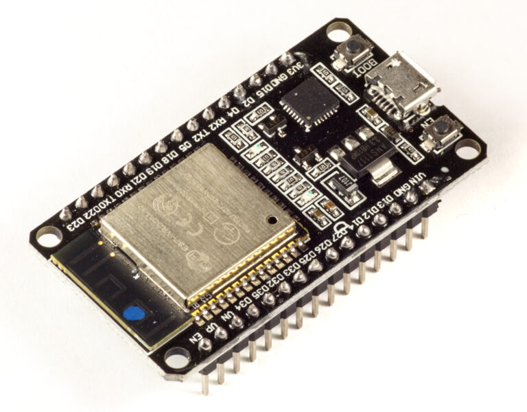
| ESP32AliExpress price development board | Runs ESPHome and acts as the 1-Wire master |
| Two or more genuine/quality DS18B20 probes | Each has a unique 64-bit ROM address |
| 4.7 kΩ resistor | Standard starting pull-up between DATA and 3.3 V |
| Optional 3.3 kΩ / 2.2 kΩ resistors | Useful for controlled testing on heavier buses |
| Twisted-pair cable | Better long-run signal integrity than random parallel hookup wire |
| Terminal blocks / junction enclosure | Reliable field wiring |
| Multimeter | Checks supply voltage, continuity and accidental shorts |
| Optional DS2482/DS2484 1-Wire master | Better choice for very long or complex networks |
| ESPHome 2026.x | Current one_wire + dallas_temp implementation |
| Home Assistant | Displays and automates all temperature channels |
The Most Important 2026 Update: ESPHome Syntax Changed
A lot of DS18B20 tutorials still show the old ESPHome syntax:
# OLD — no longer the current ESPHome syntax
dallas:
  - pin: GPIO4

sensor:
  - platform: dallas
    address: 0x1234567890ABCDEF
    name: "Temperature"
ESPHome moved 1-Wire into a general top-level component in 2024.6. The current syntax is:
# CURRENT ESPHome
one_wire:
  - platform: gpio
    pin: GPIO4

sensor:
  - platform: dallas_temp
    address: 0x1234567890ABCDEF
    name: "Temperature"
This is not cosmetic. If you copy an old DS18B20 configuration and ESPHome reports that dallas or platform: dallas is unknown, migrate to one_wire and dallas_temp.
Why Multiple DS18B20 Sensors Can Share One GPIO
1-Wire is a bus protocol. The ESP32 is the master and every DS18B20 is a slave on the same DATA line.
ESP32 GPIO4 ─────────────── DATA bus ───────────────┬─ DS18B20 #1
                                                    ├─ DS18B20 #2
                                                    ├─ DS18B20 #3
                                                    └─ DS18B20 #4

3.3V ───── 4.7kΩ ───── DATA
The master can tell the sensors apart because every genuine DS18B20 contains a unique 64-bit ROM code.
The 64-Bit Address
A DS18B20 address is not an arbitrary ESPHome ID. It is permanently stored in the sensor.
Example:
0x3C0000031AA7C828

Last byte/family portion includes DS18B20 family information
Unique ROM code identifies the individual device
This is why one ESP32 can read many DS18B20 sensors on one bus without separate GPIOs.
Address vs Index: Use Address for Permanent Installations
Current ESPHome lets you select a DS18B20 either by address: or by zero-based index:.
| Method | Advantage | Problem |
|---|---|---|
| address | Sensor identity remains tied to the physical probe | You must discover and record the address |
| index | Fast for temporary testing | Order can change if sensors are added, removed or replaced |
For a boiler, tank, solar collector or underfloor-heating manifold, never rely on index if sensor identity matters.
Address 0x...A128 = Tank Top
Address 0x...B928 = Tank Bottom
Address 0x...C428 = Solar Collector

Physical meaning stays attached to the ROM address.
How to Discover DS18B20 Addresses in ESPHome
The easiest method is to configure the 1-Wire bus only and boot the ESP32.
one_wire:
  - platform: gpio
    pin: GPIO4
ESPHome scans the bus automatically and prints discovered 1-Wire device IDs in the logs even before you define individual temperature sensors.
For a new installation, connect all probes, boot once, copy the detected addresses, then add the dallas_temp sensors.
The Best Address-Labelling Method
When several identical waterproof probes are lying on a bench, their addresses are useless unless you map each address to a physical cable.
- Connect only one new probe.
- Boot or rescan and record its ROM address.
- Label the cable immediately.
- Repeat for the next probe.
- Only then install them in pipes/tanks/floors.
A small heat test also works: hold one probe in your hand and watch which Home Assistant entity rises.
Example: Four DS18B20 Sensors on One Bus
one_wire:
  - platform: gpio
    pin: GPIO4
    id: boiler_one_wire

sensor:
  - platform: dallas_temp
    one_wire_id: boiler_one_wire
    address: 0x3C0000031AA7C828
    name: "Tank Top Temperature"
    id: tank_top_temperature
    update_interval: 30s

  - platform: dallas_temp
    one_wire_id: boiler_one_wire
    address: 0x5F00000321B9D028
    name: "Tank Bottom Temperature"
    id: tank_bottom_temperature
    update_interval: 30s

  - platform: dallas_temp
    one_wire_id: boiler_one_wire
    address: 0x7A00000317C34428
    name: "Solar Flow Temperature"
    id: solar_flow_temperature
    update_interval: 30s

  - platform: dallas_temp
    one_wire_id: boiler_one_wire
    address: 0x280000031E52A628
    name: "Solar Return Temperature"
    id: solar_return_temperature
    update_interval: 30s
The example addresses are placeholders. Use the ROM codes printed by your own sensors.
DS18B20 Wiring: Powered Mode
For ESP32/Home Assistant installations, three-wire powered mode is the default I recommend.
| DS18B20 | ESP32 |
|---|---|
| VDD | 3.3 V |
| GND | GND |
| DQ / DATA | GPIO4 example |
| 4.7 kΩ resistor | Between DATA and 3.3 V, near the ESP32/master |
ESP32 3.3V ─────────────── VDD ───────── probes
     │
     └── 4.7kΩ ──┐
                 ├──────── DATA ───────── probes
ESP32 GPIO4 ─────┘
ESP32 GND ───────────────── GND ───────── probes
External power is simpler and more robust than parasite power, especially when you have multiple probes or long cable runs.
Why the Pull-Up Resistor Is Required
1-Wire uses an open-drain/open-collector style bus. Devices actively pull the DATA line LOW, but they do not actively drive it HIGH during normal signalling.
No device pulling low
→ pull-up resistor raises DATA to logic HIGH

Master/slave pulls low
→ DATA becomes logic LOW
Without an adequate pull-up, the bus can float or rise too slowly, causing missing devices and CRC/checksum failures.
Why 4.7 kΩ Is the Standard Starting Value
Both the DS18B20 reference circuit and current ESPHome documentation use approximately 4.7 kΩ. ESPHome notes that values roughly ±1 kΩ can generally work on ordinary short buses.
For a few probes on short wiring, start with 4.7 kΩ. Do not “optimize” a working bus for no reason.
When a Lower Pull-Up Resistance Can Help
Long cable adds capacitance. More capacitance makes the DATA line rise more slowly through the pull-up resistor.
Rise behaviour roughly follows R × C

More cable → more C
Large R + large C → slower rise
Reducing the pull-up from 4.7 kΩ to 3.3 kΩ or 2.2 kΩ can sometimes improve a marginal long bus because the line charges faster.
But there are limits: the master and DS18B20 devices must still be able to pull the line LOW with the stronger pull-up. The right resistor depends on the actual network, not a universal internet rule.
Do Not Start with a 1 kΩ Pull-Up on a Normal Short Bus
A very low resistor increases current every time the bus is pulled LOW and can create new signal problems. Use the standard 4.7 kΩ first and change only when the physical bus requires it.
Long Cable: The Topology Matters More Than the Exact Metres
There is no honest single answer to “How many metres can DS18B20 run?” because 1-Wire reliability depends on:
- total cable capacitance
- distance to the farthest sensor
- number of sensors
- branch/stub lengths
- cable type
- pull-up strength
- supply voltage and voltage drop
- noise environment
- master driver hardware
A clean 30 m linear run with a few sensors can be easier than a 10 m installation with five long star branches.
1-Wire Radius vs Weight
Analog Devices uses two useful terms for long 1-Wire networks.
| Term | Meaning |
|---|---|
| Radius | Distance from the master to the farthest slave |
| Weight | Total cable connected to the network, plus electrical loading from devices/PCB/etc. |
A three-branch star of 10 m, 20 m and 30 m has a radius of 30 m but a cable weight of 60 m before adding sensor/device capacitance.
Best Topology: Linear / Daisy-Chain
ESP32 ────── probe ────── probe ────── probe ────── probe
                 │             │
               tiny          tiny
               stub          stub
For long runs, the most predictable topology is one main cable with sensors connected directly along it or using short branches.
Analog Devices defines a linear topology as a main bus where slave branches are insignificant — less than roughly 3 m in its long-line guidance.
The Problem with a Star Network
                 ┌──── 10m ─── probe
ESP32 ───────────┼──── 15m ─── probe
                 ├──── 20m ─── probe
                 └──── 25m ─── probe
An unswitched star creates impedance discontinuities. Reflections return from different branches at different times and can corrupt the tight 1-Wire timing windows.
Analog Devices explicitly describes unswitched star topology as the most difficult to make reliable and does not recommend it for long 1-Wire networks.
Why a Star Sometimes Appears to Work
On a breadboard with four 30 cm wires, practically any topology may work because the electrical network is tiny.
The same diagram scaled to four 15 m cable runs is a completely different transmission-line problem. This is why a topology that works on the bench can fail after permanent installation.
Stub Length
A stub is a branch from the main 1-Wire trunk to a sensor.
Main bus ───────────────────────────────
               │
               └──── stub ─── DS18B20
Short stubs are easier. Long stubs behave like separate transmission paths and increase reflections. If you are wiring a building, run the main trunk past the probe locations instead of home-running every sensor back to the ESP32.
Recommended Cable
For long DS18B20 runs, twisted-pair cable such as CAT5e/CAT6 is a practical choice because its geometry is consistent and it is cheap.
A useful approach is:
Pair 1: DATA + GND
Pair 2: VDD + GND (or parallel conductors for power)
Unused pairs: spare / future use
Keeping DATA twisted with a ground/reference conductor helps reject coupled noise.
Should You Use Shielded Cable?
Shielding can help in electrically hostile environments, but it adds capacitance and must be terminated thoughtfully. For normal home wiring, ordinary twisted-pair CAT cable is usually a better starting point than heavily shielded cable.
Keep DS18B20 Cable Away from Mains and Motors
- Do not cable-tie the 1-Wire run to 230 V mains for tens of metres.
- Keep distance from contactors, pumps, VFD motor outputs and ignition systems.
- Cross mains at roughly 90° where practical.
- Use proper separation required by electrical regulations.
- Never treat the low-voltage sensor cable as mains-rated isolation.
A DS18B20 bus can be logically robust but still suffer if it is routed through an electrically noisy plant room.
Multiple Sensors Increase Bus Capacitance
Each DS18B20 input contributes capacitance in addition to the cable. Adding sensors therefore makes the same cable electrically heavier.
One 20m cable + 1 sensor
≠
One 20m cable + 30 sensors
This is why “my one probe works at 40 m” does not prove a 20-probe network will work at the same distance.
A Practical Home-Automation Length Guide
The following is a practical engineering starting point, not a guaranteed DS18B20 specification:
| Network | Practical approach |
|---|---|
| < 5 m, few sensors | 4.7 kΩ, 3.3 V, ordinary powered mode; usually easy |
| 5–20 m | Use twisted pair, linear topology, good connections; still often straightforward |
| 20–50 m | Treat as a real bus: linear topology, test pull-up, avoid parasite power, verify voltage/noise |
| > 50 m or many branches/devices | Consider a dedicated 1-Wire master/bridge and segment the network |
| 100 m+ / building-wide network | Do not assume a bare ESP32 GPIO + resistor is an engineering solution |
Actual results can be better or worse. The point is to change your design mindset as the bus grows.
Why ESP32 GPIO Bit-Banging Has Limits
ESPHome’s GPIO 1-Wire implementation uses an internal ESP32 GPIO to generate the 1-Wire timing directly.
This is excellent for short and medium buses. On very large networks, a dedicated 1-Wire master can provide stronger/active pull-up behaviour and more robust line-driving characteristics.
ESPHome DS2482 / DS2484 Support
Current ESPHome supports I²C-to-1-Wire bridge devices in the DS248x family, including DS2482-100, DS2482-101, DS2482-800 and DS2484.
The component exposes an active_pullup option specifically useful for long lines or heavier bus loads.
This is the point where a project stops being “one GPIO and a resistor” and becomes a proper 1-Wire network.
Example: DS248x 1-Wire Bus
i2c:
  sda: GPIO21
  scl: GPIO22
  scan: true

one_wire:
  - platform: ds248x
    type: ds2482-100
    address: 0x18
    active_pullup: true
    id: long_one_wire_bus

sensor:
  - platform: dallas_temp
    one_wire_id: long_one_wire_bus
    address: 0x3C0000031AA7C828
    name: "Remote Tank Temperature"
Use the exact bridge configuration that matches your hardware. A dedicated bridge is most valuable when the physical network is genuinely difficult, not as a requirement for a few nearby probes.
Parasite Power: What It Is
The DS18B20 can operate with only DATA and GND by stealing energy from the 1-Wire line while it is HIGH. In this mode, VDD is connected to GND.
Parasite mode:
GND ───────── GND + VDD
DATA ──────── DQ

No separate VDD wire
It sounds ideal for long runs because one conductor disappears. In practice, it makes high-current operations harder.
Why Parasite Power Is Hard During Temperature Conversion
A DS18B20 can draw up to around 1.5 mA during temperature conversion. The normal weak 1-Wire pull-up cannot reliably supply that conversion current through a large bus.
The datasheet therefore requires a strong pull-up during conversion when parasite power is used.
For an ESP32 + several remote probes, using a third VDD conductor is usually far easier than designing around strong parasite-power pull-up control.
My Recommendation on Parasite Power
Short embedded PCB with special reason → parasite power can be valid
Multiple waterproof probes / long home wiring → use 3-wire powered mode
Do not choose parasite power merely to save one conductor in CAT5e; you already have spare conductors.
Can You Power DS18B20 from 5 V with an ESP32?
The DS18B20 itself supports external supply voltage up to 5.5 V. In some long-run installations, powering the sensor rail from 5 V can reduce voltage-drop margin problems.
However, the ESP32 DATA GPIO is not 5 V tolerant. Do not pull the 1-Wire DATA line up to 5 V and connect it directly to the ESP32.
For most projects, power the probes and pull-up from 3.3 V. If you intentionally use a 5 V sensor supply, design the DATA voltage domain correctly and keep the ESP32 GPIO within specification.
3.3 V vs 5 V on Very Long Runs
A higher sensor supply can provide more voltage-drop margin, but bus signal integrity and power are separate problems. Increasing VDD does not fix reflections caused by a bad star topology.
For a serious long network, a dedicated 1-Wire master/level/interface design is a better engineering solution than random voltage changes.
Temperature Resolution: 9, 10, 11 or 12 Bit
| Resolution | Step size | Maximum conversion time |
|---|---|---|
| 9-bit | 0.5°C | ~94 ms |
| 10-bit | 0.25°C | ~188 ms |
| 11-bit | 0.125°C | 375 ms |
| 12-bit | 0.0625°C | 750 ms |
ESPHome defaults to the maximum supported resolution for most Dallas temperature sensors: 12-bit.
Higher Resolution Is Not the Same as Higher Accuracy
The DS18B20 is specified around ±0.5°C accuracy from -10°C to +85°C. A 0.0625°C digital step at 12-bit does not mean the real-world temperature is accurate to ±0.0625°C.
Resolution = how finely the output changes
Accuracy   = how close it is to true temperature
For Home Assistant, 11-bit is often already more than enough, but leaving 12-bit is fine unless conversion time matters.
Why Lower Resolution Can Help Large Networks
Lower resolution reduces conversion time dramatically. If many probes are being sampled frequently, that can reduce how long each transaction occupies the measurement cycle.
For a boiler system updating every 30–60 seconds, 12-bit conversion time is usually irrelevant. For fast process monitoring, consider whether you actually need 12-bit.
Do Not Update Boiler Sensors Every Second Without a Reason
Most hydronic systems change slowly. A 30-second update interval is typically much more sensible than 1 second.
Room / boiler / tank → 30–60s usually excellent
Process experiment → faster if genuinely required
Less traffic also makes a marginal long bus more forgiving and avoids filling Home Assistant history with meaningless samples.
Complete ESPHome Example: Six Named Probes
one_wire:
  - platform: gpio
    pin: GPIO4
    id: heating_bus

sensor:
  - platform: dallas_temp
    one_wire_id: heating_bus
    address: 0x3C0000031AA7C828
    name: "Cylinder Top"
    resolution: 12
    update_interval: 30s

  - platform: dallas_temp
    one_wire_id: heating_bus
    address: 0x5F00000321B9D028
    name: "Cylinder Bottom"
    resolution: 12
    update_interval: 30s

  - platform: dallas_temp
    one_wire_id: heating_bus
    address: 0x7A00000317C34428
    name: "Boiler Flow"
    resolution: 12
    update_interval: 30s

  - platform: dallas_temp
    one_wire_id: heating_bus
    address: 0x280000031E52A628
    name: "Boiler Return"
    resolution: 12
    update_interval: 30s

  - platform: dallas_temp
    one_wire_id: heating_bus
    address: 0x6E00000314AE8128
    name: "UFH Flow"
    resolution: 12
    update_interval: 30s

  - platform: dallas_temp
    one_wire_id: heating_bus
    address: 0x1C00000388D31428
    name: "UFH Return"
    resolution: 12
    update_interval: 30s
Replace every example address with the address discovered from your own probe.
Why I Would Not Use index: for Those Six Sensors
If one probe fails and you replace it, the hardware-address ordering can change. An index-based configuration can then attach the wrong physical meaning to an entity.
In a heating system, that is dangerous logically: “Boiler Flow” could suddenly show the return temperature.
Multiple 1-Wire Buses on One ESP32
Sometimes the cleanest solution is to split a complicated installation into two or more buses.
one_wire:
  - platform: gpio
    pin: GPIO4
    id: boiler_bus

  - platform: gpio
    pin: GPIO5
    id: solar_bus

sensor:
  - platform: dallas_temp
    one_wire_id: boiler_bus
    address: 0x3C0000031AA7C828
    name: "Boiler Flow"

  - platform: dallas_temp
    one_wire_id: solar_bus
    address: 0x7A00000317C34428
    name: "Solar Collector"
ESPHome requires one_wire_id: when more than one bus exists.
Why Splitting the Bus Can Be Better Than Fighting It
- reduces cable weight/capacitance per bus
- reduces number of devices per bus
- can eliminate a bad star topology
- isolates faults
- makes troubleshooting easier
- one failed cable cannot take every temperature sensor offline
An ESP32 has many GPIOs. There is no prize for putting an entire building on one wire.
Fault Isolation
One major downside of a shared bus is that a hard short on DATA can disable every sensor on that bus.
One damaged probe cable shorts DATA to GND
→ entire 1-Wire bus can disappear
For critical heating/plant systems, two independent buses can provide useful fault containment.
Common Error: No Devices Found
- Check DATA and GND are not reversed.
- Confirm the pull-up resistor actually connects DATA to 3.3 V.
- Measure sensor supply voltage at the far end.
- Confirm the GPIO supports both input and output.
- Do not use an I/O expander pin for the GPIO 1-Wire master.
- Test with one short known-good probe first.
Current ESPHome explicitly requires the GPIO 1-Wire pin to be an internal microcontroller GPIO capable of bidirectional operation.
Common Error: ‘1-Wire Bus Is Held Low’
This means the master cannot see the line return HIGH.
- DATA shorted to GND
- reversed waterproof probe wiring
- damaged sensor
- wrong pin assignment
- pull-up missing
- extremely overloaded bus
Disconnect all field wiring and test the GPIO/pull-up first, then reconnect branches/probes one at a time.
Common Error: Devices Randomly Appear and Disappear
This is a classic long-line 1-Wire symptom. Analog Devices specifically notes that unreliable networks often manifest as devices mysteriously disappearing from the ROM search.
- bad star topology
- too much cable capacitance
- long stubs
- weak rise time
- voltage drop
- poor connectors
- noise
- parasite-power starvation
Do not solve a physical bus problem by repeatedly rebooting ESPHome.
Common Error: CRC / Scratchpad Checksum Invalid
The DS18B20 sends a CRC byte with its scratchpad data. Current ESPHome checks that data and can flag an invalid checksum.
A checksum error usually means the bits arriving at the ESP32 are not the bits the sensor transmitted.
Sensor temperature conversion may be fine
but
electrical communication is corrupt- improve topology
- shorten stubs
- check pull-up
- reduce noise
- check connectors
- test lower cable load
- consider active 1-Wire master
Common Error: 85°C
85°C is the DS18B20 power-on reset value of the temperature register.
If you repeatedly see exactly 85°C when the real object is nowhere near that temperature, suspect that the sensor reset or that a valid conversion was not completed/read.
- power interruption
- parasite-power failure
- conversion timing/power issue
- bad cable/connector
- marginal bus causing device resets
An occasional genuine 85°C measurement is possible in a very hot process, but an exact 85.0°C appearing after power/bus problems is diagnostically suspicious.
What About -127°C?
The DS18B20’s physical range ends at -55°C, so -127°C is not a real DS18B20 temperature. Some Arduino DallasTemperature libraries use values around -127°C as a disconnected/error sentinel.
ESPHome may represent failures differently, but if you are migrating from Arduino/MQTT code and see -127°C, treat it as a communication failure, not an Antarctic boiler.
Common Error: One Sensor Works, Five Do Not
That is strong evidence the basic pin/configuration is correct and the bus electrical load is the problem.
- measure the far-end VDD
- check topology
- remove long branches
- verify pull-up placement
- try 3.3 kΩ cautiously
- use powered mode
- split into two buses
- consider DS248x active master
Common Error: Works on USB, Fails in Final Enclosure
- different power supply noise
- sensor cable routed beside relay/mains wiring
- longer final cable
- ground connection changed
- relay/contactors inject noise
- ESP32 moved to a metal enclosure affecting other system behaviour
Always test the installed cable and final power supply, not only a breadboard.
Common Error: Waterproof Probe Wire Colours Are Wrong
Cheap waterproof DS18B20 probes do not always follow the same colour convention. Do not assume red/black/yellow is correct simply because another seller used it.
Check the seller pinout and, if uncertain, verify the probe before connecting it. Reverse-powering low-cost encapsulated probes can permanently damage them.
Clone DS18B20 Sensors
The market contains many DS18B20-compatible clones. Some work perfectly; some have unusual power, timing, resolution or calibration behaviour.
For a critical multi-sensor network, buy probes from a traceable supplier or at least test every probe before installation.
- compare all probes together at room temperature
- check address uniqueness
- test at the expected temperature range
- power-cycle repeatedly
- verify all selected resolutions work
Duplicate Addresses Should Never Happen on Genuine Parts
A genuine DS18B20 is designed with a unique 64-bit ROM code. If two cheap probes appear to have the same identity or behave strangely during search, suspect clone/counterfeit devices or a bus problem.
Calibration: Do You Need It?
For normal Home Assistant monitoring, the DS18B20’s ±0.5°C-class room/working-range accuracy is often sufficient.
For hydronic balancing or flow/return delta-T, relative agreement between probes can matter more than absolute calibration.
How to Match Several Probes
- Place all probes tightly together in the same stable thermal mass.
- Wait long enough for the waterproof sleeves/cables to equilibrate.
- Record each reading.
- Choose one reference or an external calibrated thermometer.
- Apply small ESPHome offset filters only if justified.
Do not calibrate sensors while one probe is touching a metal pipe and another is hanging in air.
ESPHome Offset Example
sensor:
  - platform: dallas_temp
    one_wire_id: heating_bus
    address: 0x3C0000031AA7C828
    name: "Boiler Flow"
    filters:
      - offset: -0.2
Document calibration offsets. Otherwise a future owner will assume the sensor is wrong when the YAML deliberately changes it.
Pipe Measurement: Installation Error Can Exceed Sensor Error
A ±0.5°C DS18B20 strapped badly to a pipe can produce a much larger error because it is measuring a mixture of pipe and room temperature.
- use thermal paste where suitable
- clamp the metal probe firmly to the pipe
- insulate over the probe from room air
- place flow/return probes consistently
- avoid mounting immediately beside a major external heat source
The sensor specification is only one part of measurement accuracy.
Water Tank Stratification
Multiple DS18B20 probes are particularly useful on a hot-water cylinder because one sensor cannot show stratification.
Tank Top    58°C
Tank Middle 46°C
Tank Bottom 28°C

→ much more useful than one average temperature
This can improve boiler/solar-diverter logic and give Home Assistant a much better picture of usable stored hot water.
Flow and Return Temperature
Two DS18B20 probes can measure heating flow and return temperatures.
ΔT = Flow Temperature - Return TemperatureThe delta can help diagnose system behaviour, but calculating heat power accurately also requires reliable flow-rate information.
Home Assistant Template: Delta-T
template:
  - sensor:
      - name: "Boiler Delta T"
        unit_of_measurement: "°C"
        state: >
          {{ states('sensor.boiler_flow')|float(0)
             - states('sensor.boiler_return')|float(0) }}
Freezer / Fridge Monitoring
Multiple probes on one 1-Wire bus are also useful for cold-storage monitoring: freezer, fridge, ambient utility room and perhaps compressor-discharge monitoring can share one ESP32.
Use sensible Home Assistant delays before alarming; opening a freezer door briefly should not immediately trigger an emergency notification.
Outdoor / Greenhouse Runs
For a greenhouse or outdoor pipe run, waterproofing the sensor tip is not enough. The cable joints, pull-up/master enclosure and connectors also need moisture protection.
Water ingress into a junction can create leakage resistance on DATA and produce intermittent CRC errors long before the sensor itself fails.
How Many DS18B20 Sensors Can One ESP32 Handle?
Protocol addressing allows many devices on one 1-Wire bus, but the practical limit is electrical and architectural rather than a small hard software number.
For Home Assistant, ask a better question: How many probes can this specific cable topology support reliably?
If you are reaching dozens of devices or building-wide cable lengths, divide the network or use dedicated 1-Wire master hardware rather than chasing a theoretical maximum.
One Bus vs Several ESP32 Nodes
| Architecture | Best when |
|---|---|
| One long 1-Wire bus | Sensors lie naturally along one cable route |
| Two/three buses on one ESP32 | Different physical branches originate near the controller |
| Several ESP32 nodes | Sensors are distributed across rooms/buildings and Wi-Fi/ESP-NOW can replace long copper runs |
| Dedicated 1-Wire master | Long/heavy professional bus must remain wired |
Sometimes Wireless Is Easier Than 80 m of 1-Wire
A second ESP32 with a short local DS18B20 bus can be more reliable than dragging a complicated star network across a building.
Plant room ESP32 → 4 local probes
Garage ESP32     → 3 local probes
Solar ESP32      → 2 local probes

Home Assistant combines all entities
Do not optimize GPIO count at the expense of system reliability.
Best Practices Checklist
- Use current ESPHome one_wire + dallas_temp syntax.
- Assign permanent sensors by ROM address.
- Use external 3-wire power.
- Start with a 4.7 kΩ pull-up at the master.
- Prefer a linear trunk with short stubs.
- Avoid large unswitched star networks.
- Use twisted pair for long cable.
- Route away from mains/motor noise.
- Use realistic 30–60 s update intervals for HVAC/tank monitoring.
- Split the bus if physical branches become awkward.
- Use DS248x/active-master hardware for genuinely long/heavy networks.
- Label each probe with its ROM address before installation.
Troubleshooting Flow
No sensors?
→ test one probe on 20 cm wire + 4.7kΩ
   ├─ still fails → pin / wiring / sensor / YAML
   └─ works
       ↓
Add installed cable
       ↓
Add probes one at a time
       ↓
Failure appears?
→ inspect topology / VDD / pull-up / noise / connector
       ↓
Still marginal?
→ split bus or use active 1-Wire master
Do Not Change Five Things at Once
When debugging, change one variable: cable, pull-up, sensor count, power mode or topology. If you simultaneously change resistor, update interval and supply voltage, you will not learn what fixed the network.
My Recommended Home Assistant Architecture
ESP32
├─ GPIO4 1-Wire bus
│   ├─ Tank Top DS18B20
│   ├─ Tank Bottom DS18B20
│   ├─ Boiler Flow DS18B20
│   └─ Boiler Return DS18B20
│
└─ ESPHome native API
       ↓
Home Assistant
├─ temperatures
├─ ΔT sensors
├─ graphs
├─ alerts
└─ heating/solar automations
Final Recommendation
The DS18B20 is unusually powerful for Home Assistant because one ESP32 GPIO can monitor a whole heating system, hot-water tank, freezer bank or greenhouse. The key is to treat 1-Wire as a real electrical bus, not as an infinitely stretchable jumper wire.
For two to six nearby probes, keep it simple: three-wire power, 4.7 kΩ pull-up, current ESPHome syntax and permanent ROM addresses.
As the installation grows, prioritize topology before software tweaks. Run one main trunk, keep stubs short, use twisted pair and avoid a large unswitched star. If the network becomes long or heavily loaded, split it across GPIOs/ESP32 nodes or use a DS248x-class active 1-Wire master.
The most common DS18B20 failures — disappearing devices, checksum errors and suspicious reset readings — are usually telling you that the physical bus is marginal. Fix the wiring and power, and the ESPHome/Home Assistant side becomes extremely reliable.
Related ESP32 Guides
- ESP32 + DS18B20 with Home Assistant – Complete Guide
- ESP32 Smart Thermostat with DS18B20/SHT45
- ESP32 AC Climate Controller for Home Assistant
- ESP32 PWM Fan Speed Control with Home Assistant
Datasheets & External Resources
All external manufacturer/framework references are collected here so the main article keeps readers inside esp32.co.uk.
- ESPHome 1-Wire Bus — current 1-Wire configuration, 4.7 kΩ pull-up guidance and address discovery.
- ESPHome GPIO 1-Wire Bus — current internal-GPIO requirements and bus configuration.
- ESPHome Dallas Temperature Sensor — current DS18B20 address/index, resolution and update-interval configuration.
- ESPHome 2024.6 1-Wire Migration — documents removal of the old dallas platform and migration to one_wire + dallas_temp.
- Analog Devices / Maxim DS18B20 Datasheet — temperature range, accuracy, unique 64-bit ROM, resolution, conversion time and parasite-power requirements.
- Analog Devices: Guidelines for Reliable Long Line 1-Wire Networks — topology, radius/weight, reflections, parasite-power issues and long-line design.
- ESPHome DS248x 1-Wire Master — DS2482/DS2484 bridge support and active pull-up option for heavier networks.