Need reliable STM32PriceAliExpress price serial output or an interactive serial command channel? On the STM32F103C8PriceAliExpress price Blue PillPriceAliExpress price, enable USART1 asynchronous mode, connect PA9 (USART1_TX) to a 3.3 V USB-to-UART adapter’s RX, connect PA10 (USART1_RX) to the adapter’s TX, and share GND. Configure both ends for 115200 baud, 8 data bits, no parity and one stop bit (8N1). After CubeMX generates the project, HAL_UART_Transmit() can send readable messages to a serial terminal; HAL_UART_Receive_IT() enables an interrupt-based receiver without continuously blocking the main loop.
In this guide, we build the entire link, show exactly how to avoid TX/RX and voltage mistakes, and move from a simple greeting to a responsive ring-buffer receiver. The examples target a Blue Pill with an STM32F103C8T6 and the STM32F1 HAL. Other STM32 families use the same overall concepts but may use different GPIO mappings, interrupt names, clock domains or peripheral driver APIs.
Quick answer: STM32 UART wiring and minimal HAL transmit
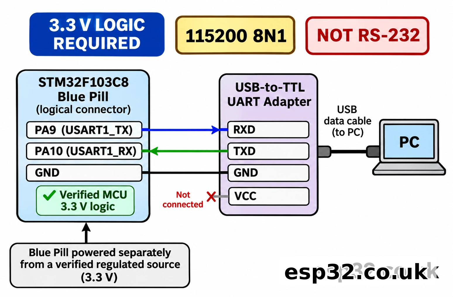
The first functional test needs just three signal connections between the Blue Pill and a USB-UART adapter. Power the STM32 separately through its normal board power input unless you have deliberately verified an adapter-supplied, regulated 3.3 V power arrangement.
| Blue Pill / STM32F103C8 | 3.3 V USB-UART adapter | Purpose |
|---|---|---|
| PA9 — USART1_TX | RXD | STM32 sends to the computer |
| PA10 — USART1_RX | TXD | Computer sends to STM32 |
| GND | GND | Shared signal reference |
| 3.3 V target rail | Not normally connected for signal-only setup | Target power is a separate decision |
With MX_USART1_UART_Init() called and huart1 correctly configured, send a message from the main loop:
/* Core/Src/main.c — insert in USER CODE sections. */
static const uint8_t greeting[] = "Hello from STM32 USART1!\r\n";

/* In the main loop, after MX_USART1_UART_Init(): */
(void)HAL_UART_Transmit(&huart1, (uint8_t *)greeting,
                        (uint16_t)(sizeof(greeting) - 1U), 100U);
HAL_Delay(1000U);
Open the adapter’s COM/TTY port at 115200 8N1 and you should see one line every second. The source is a const byte array; the cast accommodates the historic STM32F1 HAL transmit function signature. The send is deliberately blocking for a simple first test, not a pattern to use inside an interrupt. If the terminal stays blank, verify the actual COM port and test TX-only operation before changing DMA settings.
What UART and USART mean on STM32
UART means universal asynchronous receiver/transmitter: a hardware block that serialises and deserialises bits over a transmit line (TX) and a receive line (RX). A USART can also support synchronous operation with a clock signal, but the familiar three-wire USB-to-TTL serial link uses asynchronous mode. STM32CubeMX may label the peripheral USART1 while the STM32 HAL functions still start with HAL_UART_.
A standard UART frame is idle-high and begins with a low start bit. With 8N1, eight data bits follow, least significant bit first, then one high stop bit. The line is not a separate clock signal: both devices must be configured with close enough bit timings. Software that transmits ASCII sends bytes; the wire carries those bytes as timed frames, not Unicode text or human-readable voltage patterns.
UART is not the same as USB. Your laptop’s USB socket speaks USB packets to the USB-to-UART bridge chip (often CP2102, CH340 or FT232-family), and the bridge converts them into the MCU’s asynchronous TX/RX levels. The Blue Pill’s own Micro-USB port is a different circuit connected to USB D−/D+; it does not automatically become a UART terminal, and an STM32F103C8 has no factory USB DFU loader. Use the adapter for this tutorial even if your PC already recognises another device as a COM port.
| Interface | Typical wires | Protocol and signal level | Relevant use |
|---|---|---|---|
| MCU UART / USART | TX, RX, GND | Asynchronous serial, typically 3.3 V logic | Debug text, modules, commands |
| USB-to-UART bridge | USB at PC; TX/RX/GND at MCU | USB converted to TTL-level serial | Connect terminal to STM32 |
| SWD with ST-LINK | SWDIO, SWCLK, GND, reference, optional NRST | Debug/programming protocol | Flash firmware and debug code |
| RS-232 serial | TX, RX, signal GND | Inverted bipolar voltages in conventional RS-232 | Requires proper transceiver to MCU |
| RS-485 serial | Differential A/B plus reference | Differential bus physical layer | Requires external RS-485 transceiver |
Never connect an RS-232 connector directly to PA9 or PA10. Similarly, a device labelled “5 V serial” may have 5 V signal amplitudes even when it can be powered from 3.3 V. Check the I/O voltage, not just the adapter’s USB power input or the selected baud rate.
STM32F103C8 USART pins: PA9, PA10 and alternatives
The STM32F103C8 peripheral has several serial interfaces. Its default USART1 signals are PA9 TX and PA10 RX; USART2 defaults to PA2 TX and PA3 RX. The alternate-function remap feature can move USART1 to PB6/PB7 if explicitly configured, but those pins are also common I²C choices on the Blue Pill. This guide keeps the defaults to avoid pin conflicts and confusing diagrams.
| Peripheral on STM32F103C8 | Default TX | Default RX | Clock domain | Notes |
|---|---|---|---|---|
| USART1 | PA9 | PA10 | APB2 / PCLK2 | Used in all main examples |
| USART1 with remap | PB6 | PB7 | APB2 / PCLK2 | Must enable remapping; conflicts with common I²C1 wiring |
| USART2 | PA2 | PA3 | APB1 / PCLK1 | Useful second independent serial port |
| USART3 | PB10 | PB11 | APB1 / PCLK1 | Check actual board pins and alternate-use conflicts |
The MCU pin naming is unambiguous, but a Blue Pill board header may have a different physical orientation between revisions. Confirm the silkscreen against the real board before inserting wires. On the F103, PA13/PA14 are used for SWD; do not sacrifice them to configure this UART example. Also remember that the F103’s classic CAN and USB functions share some pin choices with other peripherals—CubeMX’s pinout warnings help prevent assigning two functions to one pin.
If you already own a Nucleo board, do not assume its Arduino header D0/D1 correspond to the same UART connected to onboard ST-LINK. For example, NUCLEO-F401RE/F446RE normally route their virtual COM feature through USART2 PA2/PA3; NUCLEO-G431RB commonly uses LPUART1 PA2/PA3 for its default ST-LINK VCP while Arduino D0/D1 follow a different route. Always check the actual board manual and solder bridges.
Electrical safety before you connect the USB-UART adapter
The Blue Pill is a 3.3 V system, and the STM32F103’s valid operating supply range is specified by ST. Some STM32 GPIO pads are marked five-volt tolerant under specific conditions, but that classification does not make every pin, every operating mode or an unpowered MCU safe to drive with 5 V. For repeatable results, set the USB-UART adapter’s TX output to 3.3 V logic, power the board correctly, and share ground.
A common trap is that a USB-TTL board has both a 3.3 V power pin and a separate selector for its digital TX/RX voltage. A “3.3V” silkscreen beside VCC does not prove the adapter’s TX is 3.3 V. Check its documentation or measure idle-high voltage from TXD to GND. A stable reading near 3.3 V is consistent with the desired logic level. If it sits near 5 V, change the adapter configuration or use appropriate level shifting instead of assuming compatibility.
For the signal-only configuration used in this article, connect the three signal wires and power the Blue Pill separately using a verified input path. A USB cable can provide board power through the board’s own USB/regulator arrangement, but do not accidentally connect two competing power sources together. Target board regulator quality and clone protection arrangements vary. Avoid connecting adapter VCC to a Blue Pill 5 V or 3.3 V pin unless the power topology is known.
| Check before flashing | Safe practice | Typical failure if ignored |
|---|---|---|
| USB-UART logic level | Confirm 3.3 V TX and RX compatibility | Potential overstress or unreliable highs |
| TX/RX direction | Cross STM32 TX → adapter RX, STM32 RX ← adapter TX | Blank terminal or no commands |
| Ground reference | Link MCU and adapter GND | Floating, random or absent data |
| Target supply | Use a verified regulated source | Brownouts, repeated resets |
| USB cable | Use a data-capable cable | Adapter never enumerates |
| RS-232 adapter | Use a TTL USB-UART bridge, not direct RS-232 | Electrical damage risk |
The UART logic lines are neither galvanically isolated nor suitable for long noisy cables without an appropriate physical layer. Industrial environments, motors, car electrical systems and outdoor wiring often call for protected RS-485, CAN or an isolated interface instead of long direct TTL wires.
Set up USART1 in STM32CubeMX and STM32CubeIDE
Start with a new STM32CubeMX configuration for the exact STM32F103C8Tx variant. If you are using STM32CubeIDE 2.x with a separate CubeMX installation, generate the STM32CubeIDE project in CubeMX, then import or open the resulting project in the IDE. The UI labels can differ by version, so follow the requested peripheral settings rather than a screenshot created for a different CubeMX release.
In the pinout view, set System Core → SYS → Debug → Serial Wire to keep PA13/PA14 available for ST-LINK. Under Connectivity → USART1, choose Asynchronous and verify that PA9 = USART1_TX and PA10 = USART1_RX appear. Leave hardware flow control disabled; this small adapter uses no CTS/RTS. Configure the UART parameters as follows:
| CubeMX parameter | Tutorial setting | Why |
|---|---|---|
| Mode | Asynchronous TX/RX | Both directions through PA9/PA10 |
| Baud rate | 115200 | Matches terminal configuration |
| Word length | 8 bits | Eight data bits with no parity |
| Parity | None | Ordinary 8N1 application serial |
| Stop bits | 1 | One stop bit |
| Hardware flow control | None | No RTS/CTS wires |
| Oversampling | Device/HAL default | STM32F1 USART implements 16× timing |
| NVIC USART1 interrupt | Disabled for first polling test; enabled for interrupt example | Avoid accidental IRQ code without handler |
| Clock selection | Use a verified system/APB clock configuration | Baud divisor derives from peripheral clock |
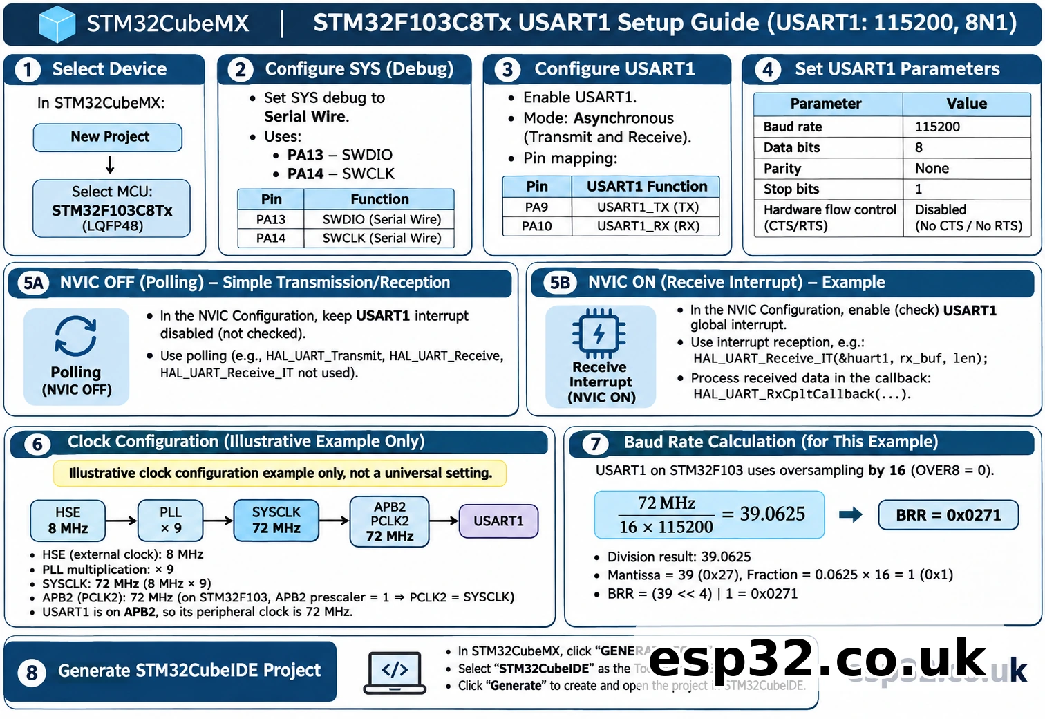
Generate the project and examine Core/Src/usart.c (or the generated equivalent for your project layout). The generated MX_USART1_UART_Init() configures a global UART_HandleTypeDef huart1 and calls the HAL. Depending on the code-generator version, the USART GPIO and clock setup may appear in HAL_UART_MspInit() inside stm32f1xx_hal_msp.c. Do not edit generated setup blindly: change the .ioc / CubeMX source configuration and regenerate where appropriate.
When inserting application code, put it inside CubeMX’s USER CODE BEGIN / USER CODE END sections. This reduces the chance that regeneration overwrites your functions or variables. Keep the generated order in main()—HAL_Init(), clock setup, GPIO/peripheral initialization and then the main loop. In particular, transmitting before MX_USART1_UART_Init() is a common reason for apparently silent serial output.
A clock setting can change your baud rate
The baud-rate generator depends on the actual peripheral bus clock. On the STM32F103, USART1 is clocked by PCLK2 (APB2), whereas USART2 and USART3 are clocked by PCLK1 (APB1). A typical Blue Pill arrangement uses an 8 MHz external oscillator multiplied by a PLL to create 72 MHz SYSCLK, with PCLK2 at 72 MHz and PCLK1 at 36 MHz. That arrangement is an example, not proof that every Blue Pill is configured that way.
For asynchronous USART1 using 16× oversampling, a useful conceptual relationship is:
USARTDIV = PCLK2 / (16 × baud)
At 72,000,000 Hz PCLK2 and 115,200 baud, USARTDIV = 39.0625: the STM32F1’s BRR encoding uses mantissa 39 and fraction 1, giving USART1->BRR = 0x0271. CubeMX/HAL performs the divisor programming for you; don’t hard-code that value unless you have confirmed the bus frequency. ST’s RM0008 includes the official calculation and baud-error tables. If your code assumes 72 MHz but the chip is actually running from an 8 MHz clock, the terminal output may look like random characters or not decode at all.
| Symptom | Clock-related cause | First check |
|---|---|---|
| Output at unexpected speed | Actual PCLK differs from configured clock | CubeMX clock tree and HAL_RCC_GetPCLK2Freq() |
| Garbled ASCII at 115200 | Baud mismatch or unstable oscillator | Confirm 8N1 and compare actual PCLK2 |
| Everything stops after clock startup | Incorrect HSE/PLL mode for the board | Check crystal and HSE source; start with HSI if appropriate |
| UART works until sleep/wake | Peripheral or system clock changed | Re-evaluate clocks and reinitialize as required |
Beware of confusing UART baud rate with the SWD clock frequency shown in a debugger tool. They control entirely different interfaces. A stable UART link at 115200 does not imply that the ST-LINK SWD interface runs at that frequency, or vice versa.
Send debug text with HAL_UART_Transmit
Once the project builds and the adapter shows as a serial port, begin with transmit only. That removes the receive wiring and interrupt configuration from the first diagnosis. The simplest code is placed in the generated while (1) after USART1 initialization:
/* Example: send a periodic heartbeat on USART1. */
static const uint8_t heartbeat[] = "STM32 USART1 ready\r\n";

while (1)
{
    HAL_StatusTypeDef status = HAL_UART_Transmit(
        &huart1, (uint8_t *)heartbeat,
        (uint16_t)(sizeof(heartbeat) - 1U), 100U);

    if (status != HAL_OK)
    {
        /* Set a breakpoint or increment an error counter here. */
    }
    HAL_Delay(1000U);
}
HAL_UART_Transmit() sends a byte buffer and waits for completion or timeout. Its fourth argument is a timeout in HAL ticks (normally milliseconds with the default tick setup), not a baud rate. The function returns a status (HAL_OK, HAL_TIMEOUT, HAL_BUSY or HAL_ERROR); silently ignoring errors can hide wiring and initialization faults. Passing sizeof(heartbeat) without subtracting one would also transmit the terminating C NUL byte, which can appear as a non-printable terminal character.
Use \r\n if you want the conventional carriage-return-plus-line-feed sequence. Some terminal settings treat \n alone correctly, while others need or automatically insert carriage returns. The line-ending choice has nothing to do with the electrical UART framing or parity setting.
A 115200-baud 8N1 link transmits roughly 11,520 payload bytes per second in the ideal continuous case because every 8-bit data byte takes about 10 bit times including start and stop. Protocol overhead, inter-message gaps, MCU processing, adapter buffering and terminal software reduce practical throughput. UART is adequate for status logs and modest control traffic, but a log generator that sends data faster than the line can carry may stall a blocking application.
Receive a character using polling
Polling is the easiest way to demonstrate that both TX and RX wires are correct. The following code waits up to 20 ms for one byte; when a byte arrives, it echoes that exact byte to the terminal. A timeout simply means that no character was available during that interval, not that the wiring is necessarily broken.
uint8_t incoming = 0U;

while (1)
{
    HAL_StatusTypeDef rx = HAL_UART_Receive(&huart1, &incoming, 1U, 20U);
    if (rx == HAL_OK)
    {
        (void)HAL_UART_Transmit(&huart1, &incoming, 1U, 100U);
    }
    else if (rx == HAL_ERROR)
    {
        /* Inspect HAL_UART_GetError(&huart1) while debugging. */
    }
    /* HAL_TIMEOUT is normal if the terminal is idle. */
}
Type a few characters in the terminal. If you see two of each character, the terminal may have local echo enabled: one copy is displayed locally and the other comes from the STM32. Disable local echo to test the MCU’s response. If the periodic transmit example works but the echo never returns, double-check the adapter’s TXD to PA10 RX connection and confirm the terminal application actually transmits characters as you type (some applications wait for Enter).
HAL_UART_Receive() in polling mode blocks up to the timeout. This is fine for a teaching demo but unsuitable for an application that must maintain precise timing, service a sensor quickly or react to multiple events during an indefinite wait. Passing HAL_MAX_DELAY can stall the main loop until data arrives. The next approach uses a receive interrupt to avoid waiting for every character in the foreground.
Receive data using a USART1 interrupt and a small ring buffer
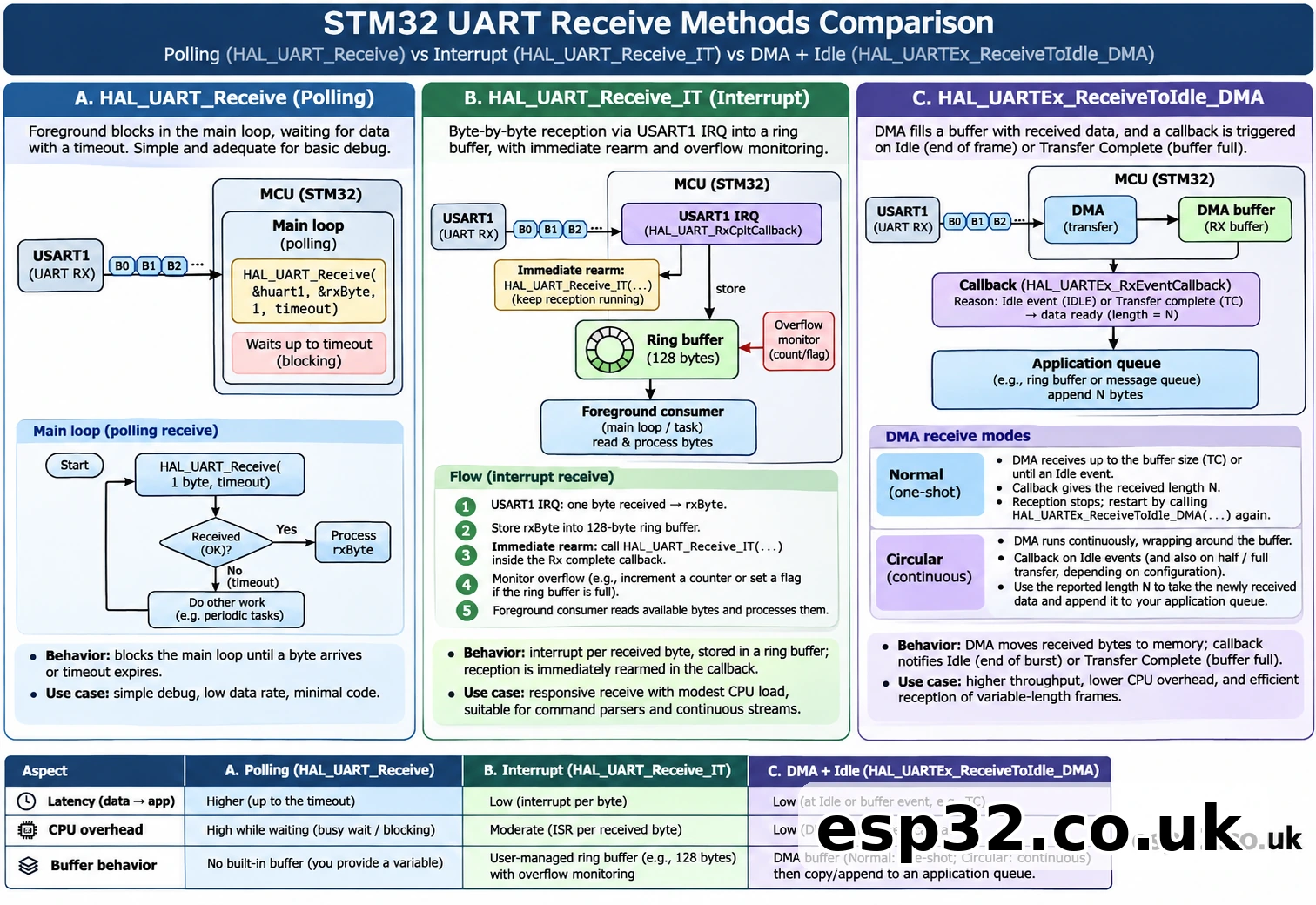
Interrupt-driven reception lets the CPU continue other foreground tasks while USART hardware collects serial bytes. First enable USART1 global interrupt in CubeMX’s NVIC settings and regenerate. Confirm the generated USART1_IRQHandler() calls HAL_UART_IRQHandler(&huart1). If the vector is missing or still runs a different handler, the HAL receive-complete callback will never execute as expected.
For short commands, receive one byte at a time into rxByte, copy it into a fixed-size ring buffer in the callback, then immediately arm the next receive. The main loop removes buffered bytes and sends them back. The example uses a buffer size of 128 bytes with one slot deliberately left empty to distinguish full from empty. It is a teaching pattern for modest data rates—not a lossless high-speed data-acquisition system.
/* Add under USER CODE BEGIN PV (or equivalent). */
#define UART_RX_CAPACITY 128U
static uint8_t rxByte;
static uint8_t rxRing[UART_RX_CAPACITY];
static volatile uint16_t rxHead = 0U;
static volatile uint16_t rxTail = 0U;
static volatile uint32_t rxDropped = 0U;

/* Call ONCE after MX_USART1_UART_Init(), before while (1). */
if (HAL_UART_Receive_IT(&huart1, &rxByte, 1U) != HAL_OK)
{
    Error_Handler();
}

/* Implement under USER CODE BEGIN 4. */
void HAL_UART_RxCpltCallback(UART_HandleTypeDef *huart)
{
    if (huart->Instance != USART1) return;

    const uint16_t next = (uint16_t)((rxHead + 1U) % UART_RX_CAPACITY);
    if (next != rxTail)
    {
        rxRing[rxHead] = rxByte;
        rxHead = next;
    }
    else
    {
        rxDropped++;
    }

    /* Keep this callback short; never perform blocking UART TX here. */
    (void)HAL_UART_Receive_IT(&huart1, &rxByte, 1U);
}

/* Foreground: use INSIDE while (1), not inside the callback. */
if (rxTail != rxHead)
{
    uint8_t character = rxRing[rxTail];
    rxTail = (uint16_t)((rxTail + 1U) % UART_RX_CAPACITY);
    (void)HAL_UART_Transmit(&huart1, &character, 1U, 100U);
}
The callback executes in interrupt context. It copies the byte, updates an index and rearms reception. It must not call HAL_Delay(), write long strings to the same UART using a blocking function, or parse a complex JSON message. With the default 8N1 setting, each byte costs about 87 μs at 115200 baud; an interrupt routine that takes longer than incoming byte intervals can provoke overruns. The rxDropped counter only measures software ring-buffer overflow; separate hardware overrun errors can also occur and must be monitored through the HAL error reporting path.
This ring-buffer example assumes one producer (USART1 IRQ) and one consumer (main loop), naturally aligned index reads/writes on the Cortex-M3, and no other code modifying those indexes. For multithreaded RTOS code or a second ISR consumer, add a proper synchronisation design. If the UART becomes stuck after a framing or overrun error, inspect HAL_UART_ErrorCallback(), HAL_UART_GetError() and the HAL state; simply calling HAL_UART_Receive_IT() repeatedly while HAL_BUSY may not recover the peripheral.
When DMA and receive-to-idle are a better fit
For larger, bursty packets or higher baud rates, a DMA receiver can move bytes from the USART data register into RAM without generating a receive-complete interrupt for every character. On STM32F103, the actual DMA channel mapping is defined by the device; let CubeMX configure the matching USART1 DMA RX request, channel, direction, circular/normal mode and interrupt priority. Do not copy a DMA channel number from an STM32F4, G4 or H7 tutorial.
Contemporary STM32 HAL F1 versions include HAL_UARTEx_ReceiveToIdle_DMA(), which can report a receive event after a period of line idleness or when the DMA buffer reaches a defined condition. Confirm that your installed STM32CubeF1 HAL version includes this API rather than assuming every historical F1 package does. The callback receives the amount of data reported by the HAL; in circular mode, the parameter can represent a buffer position and requires careful handling of wraparound and repeated callbacks.
/* API sketch: normal-mode DMA, generated DMA/NVIC configured first. */
static uint8_t dmaRx[128];

HAL_StatusTypeDef started = HAL_UARTEx_ReceiveToIdle_DMA(
    &huart1, dmaRx, sizeof(dmaRx));
if (started != HAL_OK)
{
    Error_Handler();
}

/* Supply HAL_UARTEx_RxEventCallback(UART_HandleTypeDef*, uint16_t)
   to copy the received bytes into an application queue. Re-arm when
   the chosen DMA mode/HAL state permits. Do not process or print
   a large packet inside an IRQ callback. */
The code above illustrates starting the API, not a complete DMA protocol implementation. A production receiver must handle idle events, half/full-buffer events as appropriate, ownership of the DMA buffer, overrun and HAL state transitions. In normal DMA mode, rearm only when the receive operation has completed or ended according to your HAL version. In circular DMA mode, track the previous write position so you neither process data twice nor miss data crossing the end of the buffer.
DMA cannot solve a bad ground, a 5 V adapter on a 3.3 V system, an incorrect clock or a terminal with the wrong parity. Start with the blocking greeting, prove the receive wire using polling, then add interrupts or DMA when throughput measurements justify the complexity.
Turn bytes into useful commands instead of treating UART as messages
A UART link transports a byte stream. It does not preserve message boundaries, guarantee that a whole line arrives in one interrupt, or provide a checksum by itself. If you receive LED ON\n in several pieces, that is normal. Applications should define a message format such as newline-terminated ASCII lines, a fixed binary length, or framed packets with length and CRC fields.
For a line-oriented command parser, maintain an application buffer, append non-newline characters, and process the complete line only after receiving \n or \r\n. Cap the length (for example 64 bytes), reject overflow explicitly and avoid functions that assume arbitrary serial data has a terminating NUL byte. Compare exact commands; don’t allow a partial prefix to trigger a potentially dangerous action. Keep incoming commands separate from debug logging when the UART carries control messages.
| Application | Good initial framing | Why |
|---|---|---|
| Human-readable debug | Lines ending in \r\n | Easy terminal display |
| Basic LED or relay commands | Bounded newline-terminated commands | Simple parser and acknowledgements |
| Sensor binary stream | Sync + length + payload + CRC | Detect corruption and resynchronise |
| Modbus RTU | Modbus framing and CRC, correct RS-485 layer | Interoperable industrial serial |
| Firmware update link | Defined bootloader protocol and validation | Avoid corrupted images and unsafe writes |
Security and robustness matter even for a local UART. Treat received bytes as untrusted input, validate lengths, handle timing and retries, and never interpret arbitrary strings as format strings in printf. If a serial command controls a motor, actuator or power stage, introduce command limits, an independent safe state and a timeout so a stalled serial session cannot leave outputs energised indefinitely.
Is printf redirected to UART automatically?
No. Standard C printf() generally goes to whatever output backend your toolchain links; a new CubeMX project does not guarantee that it will appear on USART1. Some toolchain configurations use semihosting, SWV/ITM, a weak _write stub or a retargeted character function. The precise hook depends on the C library and project build settings.
For an early diagnostic, call HAL_UART_Transmit() directly. When the circuit works, you may choose to retarget _write() using the project’s C library conventions, but note that doing so makes normal printf potentially blocking. Avoid calling it from an ISR and prevent recursive logging inside UART error handlers. printf with floating-point formatting can increase flash usage on the F103C8; enable that feature only if needed and confirm there is enough memory.
If you want both a debugging channel and a device protocol, consider using USART1 for the user-facing protocol and USART2 or SWO for instrumentation, subject to your board’s pins and available tools. A single UART used for both binary framing and free-form console messages becomes difficult to parse reliably.
UART bootloader versus application UART: do not mix their settings
The STM32F103C8 has a factory system-memory bootloader that can use USART1 on PA9/PA10 after the appropriate BOOT0/BOOT1 selection and reset. This is a separate piece of ROM firmware from the application running in user flash. Its serial framing/protocol is not the same as whatever your application configures for a human-readable terminal. ST’s bootloader documentation specifies even parity for the relevant F103 serial loader, typically described as 8E1 at the wire/protocol level.
| Topic | Your application UART tutorial | Factory ROM USART bootloader |
|---|---|---|
| When it runs | BOOT0 low, normal application boot | Boot selection enters system memory |
| Purpose | Status logs, sensors and commands | Read/write flash through ST boot protocol |
| Serial framing | We choose 115200 8N1 | ST bootloader protocol with even parity (8E1) |
| Software | Your HAL code | ST ROM loader / CubeProgrammer |
| USB connector | Not involved in UART wiring | F103C8 has no native factory USB DFU path |
For normal SWD programming, BOOT0 can remain low. For serial ROM loading, enter the appropriate boot mode, program using STM32CubeProgrammer or a compatible loader, then restore BOOT0 low and reset. A serial bootloader connection that works in 8E1 does not mean an 8N1 serial terminal will display readable application text before firmware actually runs.
UART troubleshooting: a symptom-based workflow
Use a minimal proven configuration and test in layers. Do not change GPIO remapping, clock trees, DMA modes and adapter drivers at the same time; doing so removes the evidence needed to isolate the fault.
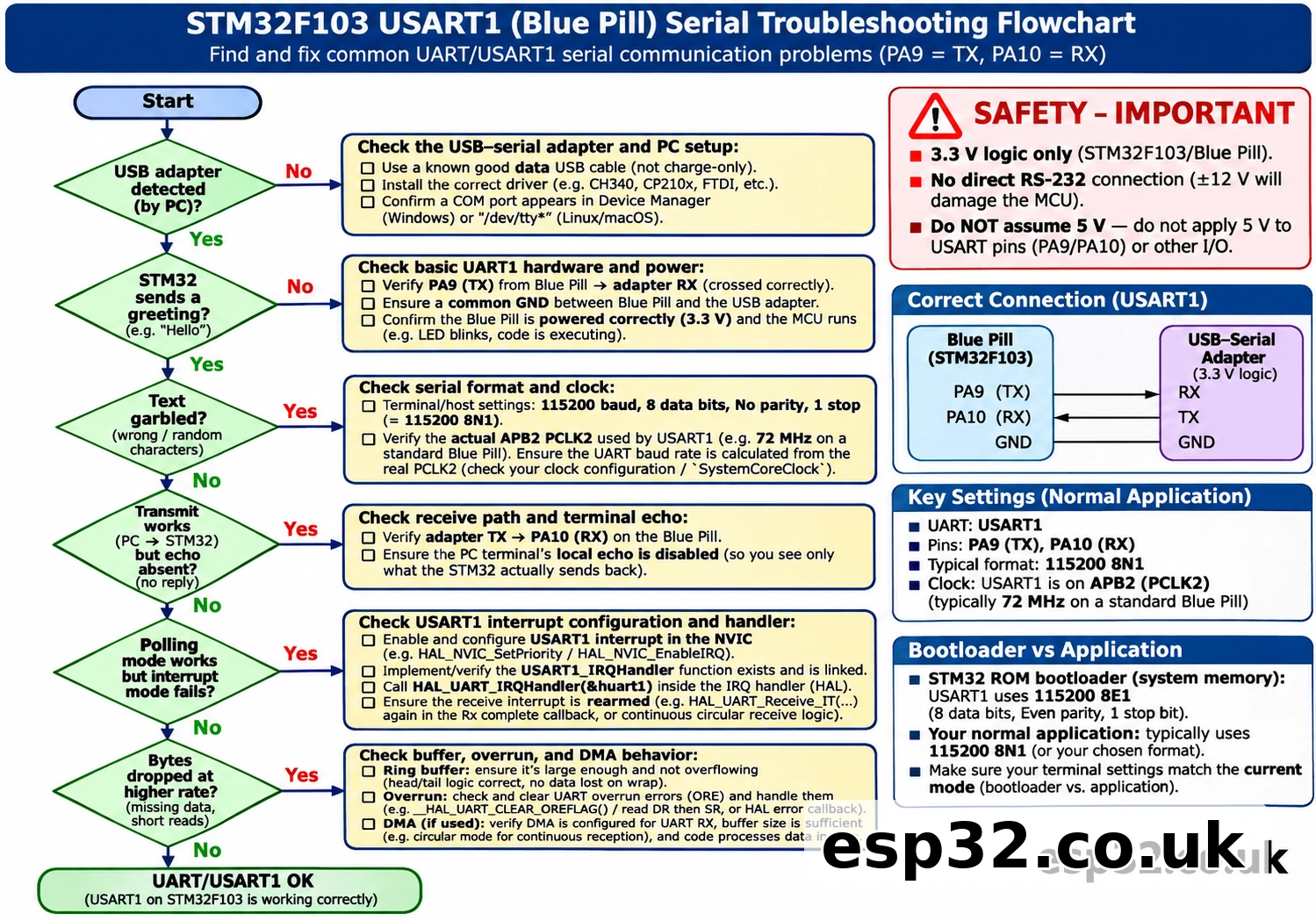
| Symptom | Most likely checks | Practical next step |
|---|---|---|
| Adapter does not appear on PC | USB cable/driver/port | Try a data cable and check Device Manager or /dev/tty* |
| Terminal is blank | TX/RX crossed incorrectly, GND missing, wrong COM port | Test PA9 TX → adapter RXD, common GND, periodic greeting |
| TX works, RX not working | Adapter TXD not reaching PA10, terminal local settings | Try polling echo; inspect voltage on PA10 |
| Garbled or unreadable characters | Wrong baud, clock configuration, parity or stop bits | Confirm 115200 8N1 and real PCLK2 |
| A character appears twice | Terminal local echo | Disable local echo, then test again |
| USART IRQ callback never runs | USART1 NVIC or IRQ handler missing | Check USART1_IRQHandler calls HAL_UART_IRQHandler |
| Interrupt works briefly then stops | Receive not rearmed or overrun/error state | Re-arm in callback and inspect HAL error codes |
| Bytes lost at higher rates | Slow IRQ work, tiny queue, blocking TX | Count dropped bytes; move to DMA/flow control if appropriate |
| Printed line lacks proper breaks | Terminal CR/LF setting | Use \r\n and verify terminal options |
| Blue Pill resets during serial activity | Power conflict, brownout or bad regulator | Measure 3.3 V rail under load; remove duplicate supplies |
| UART bootloader responds, application does not | Boot mode not restored or app uses different framing | Set BOOT0 low, reset and open terminal at 8N1 |
Troubleshooting the PC’s serial port
On Windows, find the USB-UART bridge in Device Manager under Ports (COM & LPT) and note its COM number. On Linux, a CP210x device commonly appears as /dev/ttyUSB0 and some CDC-class adapters appear as /dev/ttyACM0; verify the actual dmesg output rather than assuming a fixed name. On macOS, check /dev/cu.* for the connected serial device. Install drivers from trusted manufacturer sources when necessary rather than relying on unrelated download sites.
Close any second serial monitor before opening the port. Many operating systems and terminal programs allow just one process to hold an exclusive serial connection, so an IDE monitor already using COM5 can prevent CubeProgrammer or another terminal from opening it. For a quick self-test, some USB-UART adapters can loop their own TXD to RXD while disconnected from the MCU; typing should then echo locally through the adapter, which verifies the PC-to-adapter half of the path.
HAL errors and hardware overruns
Serial overruns occur when new incoming data arrives before previously received data is consumed or the hardware is serviced in time. The USART may set an overrun error flag, and the F1 HAL may report error bits through HAL_UART_GetError(). Error handling is stateful; blindly clearing a flag or restarting DMA without checking the HAL driver’s requirements can make the next receive harder to diagnose.
Inspect huart1.ErrorCode, HAL_UART_GetState() and the documented receive/error callback flow in the exact HAL package generated by CubeMX. Confirm that the right interrupt and DMA handlers call the right HAL functions. If debugging an infrequent failure, add lightweight counters for RX callbacks, ring overflow and HAL errors, then read those counters under the debugger instead of printing verbose messages inside the interrupt.
Choosing between polling, interrupts and DMA
There is no universal best receiver for every STM32 project. Pick the simplest method that meets its latency and throughput needs, then validate with realistic traffic rather than only one-character tests.
| Technique | Best for | Main limitations |
|---|---|---|
Blocking HAL_UART_Receive() | First test, occasional commands | Main loop waits up to timeout |
Interrupt HAL_UART_Receive_IT() | Modest commands, responsive control loop | IRQ overhead, buffer management and overrun handling |
| Normal DMA + IDLE | Bursty bounded packets | Must manage event sizes and rearming |
| Circular DMA + IDLE | Sustained variable-length streams | Write-position tracking, wraparound and concurrency |
| Hardware flow control RTS/CTS | Compatible higher-throughput links | Extra pins and both devices must support it |
A practical progression is TX greeting → polling echo → interrupt ring → DMA. Keep each test program as a known-good baseline. If a project later fails only at a higher baud rate, run the old low-rate test and measure clocks, buffer occupancy and lost bytes before changing chips or libraries.
Common questions about STM32 UART
Can I connect an STM32 Blue Pill directly to my computer’s USB port for UART?
Not simply by connecting PA9/PA10 to USB. A USB-UART converter is needed for the asynchronous TTL serial pins. Native USB CDC is possible with appropriate MCU USB firmware and board wiring, but that is a different implementation from USART1 on PA9/PA10 and does not make the factory F103 ROM loader a USB DFU bootloader.
Do I need to connect both TX and RX to print messages?
No. For a one-way status stream, STM32 TX → adapter RX plus common ground is sufficient. For interactive echo or commands, add adapter TX → STM32 RX. Supply power through a verified route, independently of the signal connections.
Why does 115200 work on one STM32 board but not on another?
The configured and actual peripheral clocks may differ, the wrong UART may be selected, or the second board may route its USB virtual COM interface through another peripheral. Check the exact MCU, its PCLK domain and the actual board-level UART/USB connections. Do not assume identical Arduino header labels across Nucleo variants.
Is a 5 V USB-UART converter safe with an STM32F103?
Use an adapter with verified 3.3 V logic for the example. Some F103 digital pins have datasheet-defined FT input capability under specific conditions, but it is unsafe to generalise that to every pin, analog mode or an unpowered chip. A 5 V power pin and 3.3 V TX output are separate properties; verify both.
Is the USART1 bootloader’s 8E1 setting also required for HAL_UART_Transmit?
No. The factory bootloader and your application are different firmware environments. This tutorial deliberately chooses 8N1 for application text and expects the terminal to match; the ROM bootloader uses its own documented protocol and parity configuration.
Should I jump straight to UART DMA on a Blue Pill?
Only when required. First prove your physical link and clock with a small blocking transmission, then use the polling receiver to verify the second wire. DMA is useful for throughput, but it does not compensate for incorrect voltage, serial framing or an unstable supply.
Does receiving exactly one byte at a time guarantee no data loss?
No. Interrupt latency, preemption, ring-buffer overflow and the physical line rate can cause dropped bytes even if the callback is correct. Monitor errors and design a protocol with framing, checks and retransmission where reliable delivery matters. DMA or hardware flow control can reduce loss in the right application.
Related esp32.co.uk/ tutorials and official technical references
The logical next steps after this esp32.co.uk/ UART guide are to add an I²C sensor, use SPI for a display or memory device, and apply interrupt/DMA techniques to realistic binary data. For foundation and programming details, see our STM32 GPIO and LED blink guide, Blue Pill Arduino IDE 2 guide, STM32CubeProgrammer flashing guide, and STM32 GPIO 5 V tolerance guide. Check the destination slugs on the live site if you have renamed a post after import.
- ST — STM32F103C8 product and official device data
- ST — RM0008 reference manual: USART, AFIO remap and APB clocks
- STMicroelectronics — STM32F1 HAL UART driver source
- STMicroelectronics — STM32F1 HAL UART API declarations
- ST — AN2606 system-memory boot mode application note
This is a documentation-based engineering tutorial. Serial code and wiring examples have not been bench-tested on every Blue Pill or USB-UART adapter revision. Verify pin labels, logic voltage and target power before connecting equipment.