A Blue PillPriceAliExpress price can stop communicating with an I²C target after a reset or interrupted transfer. Sometimes SDA is physically held low. Sometimes SCL never rises. The STM32F103 also has a documented condition in which the peripheral reports BUSY while both wires are high. This esp32.co.uk/ guide shows how to tell those cases apart at the pins and recover a single-controller bus using CubeF1 HAL and open-drain GPIO.
The lab uses I2C1 on PB6 and PB7, external 3.3 V pull-ups and a known target on a short bench bus. The recovery routine samples both wires, bounds every level wait, counts the clocks it actually observes and restores the peripheral only after the wires are released. If an idle electrical bus still reports BUSY after ordinary reinitialization, the code attempts the device-specific sequence from ST errata ES096. A final address probe checks that the target responds again.
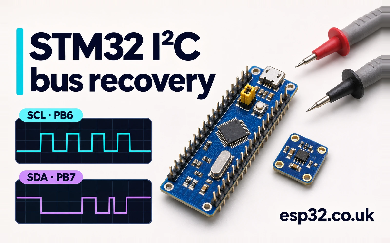
Start with the levels at the pins
An idle I²C bus has both lines high. The pull-up resistors make the high state when every attached output releases the wire. A controller or target can pull a line low. Read the actual electrical level at SCL and SDA, using a meter for a static fault and a scope for edges or intermittent activity. The GPIO input register can provide a quick digital snapshot even while the pins use their alternate function. It cannot show a slow rise, overshoot or a voltage that sits too close to the receiving threshold.
The STM32PriceAliExpress price HAL return value, the handle state and the hardware BUSY bit give three separate observations. The HAL may return HAL_BUSY because a handle is occupied or a bus wait failed. I2C_SR2.BUSY describes the peripheral’s bus state. The two pin levels describe the wires. A report of BUSY together with a genuinely low line needs a different investigation from a persistent BUSY with both lines at 3.3 V. A NACK on an otherwise healthy bus may simply mean the address is wrong or the target is temporarily unavailable. STM32 I²C setup and scanner guide
| SCL | SDA | Initial observation | Next check |
|---|---|---|---|
| High | High | Idle wires | Check SR2 BUSY, then address and target power |
| High | Low | Data wire held low | Release the controller outputs and see whether SDA stays low |
| Low | High or low | Clock cannot rise | Release SCL and allow bounded time for stretching |
| Edges visible | Edges visible | A transaction or noise may be present | Confirm the bus is idle and the recovery caller has exclusive control |
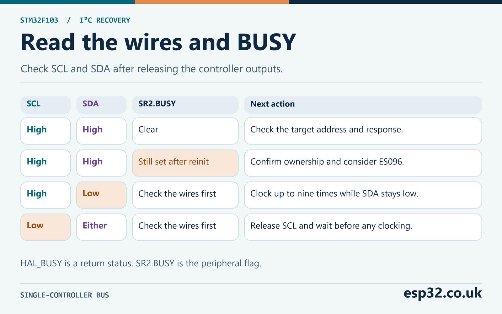
The initial line snapshot is useful because the controller itself can be the source of a low. For example, a stalled peripheral may still hold SCL. If the line rises as soon as you disable that peripheral and release the GPIO latch, the recovery routine sees a clear clock and can continue. If the line remains low, find which target, connector or board is holding it before retrying. Probe at the controller and the target. A cable fault can produce different readings at the two ends, and only the affected segment may need isolation.
A frozen low at the bench is easier to diagnose than an intermittent fault. Capture a normal transaction first and save the expected address, ACK bits, edges and STOP. When a later capture stalls, inspect the last few clock edges and whether the transaction had reached an address, data byte or acknowledgement. A reset partway through a byte can leave a powered target expecting more clocks. A persistent low with every target disconnected instead points to the controller board, wiring, pull-up network or probe reference.
When investigating a target that stays powered while the MCU resets, keep the probe on both wires across the reset. Mark the reset event with a spare scope channel if you have one. A target may retain protocol state until it sees a valid sequence on the bus. Restarting the controller initializes its own registers and leaves that target state intact. If the first transfer after reset fails, the useful evidence is the final edge before reset and what happened when the controller released its outputs afterward.
On the bench, record the HAL error code immediately after the failed transaction and before calling recovery. HAL initialization can clear the handle’s error field, so reading it later can erase the reason you entered the recovery path. Take the pin snapshot only after you have exclusive ownership. During a transfer some status reads can participate in flag-clearing sequences, including the SR1 then SR2 sequence for ADDR on STM32F1. Use a scope for live activity and collect the firmware’s before-and-after snapshots at the controlled boundary.
Wire a short 3.3 V recovery bench
Use a genuine STM32F103C8PriceAliExpress price Blue Pill, a programmer, one I²C target that supports 3.3 V and two pull-up resistors. The default I2C1 mapping is PB6 for SCL and PB7 for SDA. Some F103 projects remap I2C1 to PB8 and PB9. The supplied code checks the remap field and refuses that setup, since it samples and drives PB6 and PB7. Confirm the labels on your board and leave the debug interface on its normal Serial Wire pins. ST STM32F103C8 datasheet · Blue Pill pinout
| Blue Pill or supply | Connect to | Bench detail |
|---|---|---|
| PB6, I2C1_SCL | Target SCL | One pull-up from this node to 3.3 V |
| PB7, I2C1_SDA | Target SDA | One pull-up from this node to 3.3 V |
| GND | Target ground and instrument ground | Use a short common return |
| 3.3 V | Target VDD if appropriate and pull-up rail | Check breakout power and logic requirements |
| SCL and SDA | Scope channels or logic analyser inputs | Probe both wires at the target during fault diagnosis |
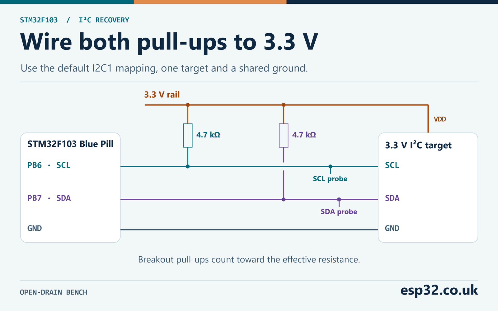
On a short bench, 4.7 kΩ per line is a reasonable starting point once you account for pull-ups already on the modules. Two 4.7 kΩ resistors on the same line in parallel give 2.35 kΩ. That can improve rise time while doubling the approximate pull-up current during a low. Read the breakout schematic or measure the network with power off, allowing for other paths through the circuit. A module that pulls to 5 V belongs outside this 3.3 V lab unless it has suitable level translation. Some boards accept 5 V on a power pin while their I²C pull-ups connect to an internal rail, so check what is actually wired.
Estimate the rise time from the effective pull-up and the total capacitance. The first-order 30% to 70% rise time is approximately 0.8473 × R × C. At 4.7 kΩ and 200 pF that is about 0.796 µs, below the 1 µs Standard-mode rise-time limit. The same capacitance at 2.2 kΩ gives about 0.373 µs. At 200 pF the 1 µs limit corresponds to about 5.90 kΩ. These calculations are a starting point. Measure at the target because connector, wiring, input and probe capacitance all contribute. NXP I²C-bus specification UM10204
There is also a lower resistance limit set by the devices’ ability to pull the line low. For example, assuming a device guarantees 0.4 V or less at 3 mA, the nominal lower bound at 3.3 V is (3.3 − 0.4) ÷ 0.003 ≈ 967 Ω. Confirm the weakest sink on the bus, including a level translator if present. Measure the low plateau and the rise separately. A low that sits too high calls for a different correction from a high that arrives too late.
The recovery GPIO uses open-drain mode on both wires. Writing a one to the output latch releases the line. If the input register still says low, another output, a short or the electrical network may be preventing the line from rising. Forcing a high with a push-pull output could fight a target that is holding low. The recovery code preloads the GPIO latch high before changing mode and then verifies each clock release at the input, so the count represents observed clock edges rather than just output writes. ST RM0008 reference manual
Measure each wire independently. A board with the right SCL pull-up can still have a missing SDA resistor, and a logic analyser may show a floating wire as a plausible digital level. On the scope, measure the 30% and 70% crossings from the actual 3.3 V reference at the target, roughly 0.99 V and 2.31 V for an ideal rail. At 4.7 kΩ, a measured 1.2 µs rise corresponds to about 301 pF in the simple RC model. That estimate is less meaningful on a bus with an active rise accelerator or a translator that changes the shape of the edge. Record the waveform and the supply before replacing parts.
Inspect how the pull-ups are distributed if you disconnect devices during diagnosis. A target module may carry the only resistors on a line. Removing that module can remove both the suspected fault and the means of restoring a high level, which makes the test ambiguous. Keep a known pair of pull-ups on the segment being tested. Confirm the high level after each change. If you measure a low at the controller and a high at the target, check continuity and the ground connection before changing the firmware timeout.
Clear a target holding SDA low
The lab is for a single controller with no DMA or interrupt-driven I²C transfer in progress. Give recovery the same exclusive ownership as an ordinary bus transaction. A second controller may legitimately be talking even when the local handle appears idle. GPIO clocks or a forced STOP would interfere with that controller. In an RTOS application, take the bus lock and coordinate the shutdown of any asynchronous transfer before calling this blocking routine. The handle check in the example is an additional guard and does not acquire that lock for you.
After disabling the I²C peripheral, configure both pins as released open-drain GPIO and wait for SCL to read high. If it cannot rise within the lab timeout, return I2C_REC_SCL_LOW. The standard’s bus-clear guidance for a clock stuck low is to use an available target reset or cycle power as appropriate. Check for stretching, a damaged device, a low rail or a wiring short before choosing that action. The firmware cannot create a valid rising edge while another device holds SCL low. NXP UM10204, bus clear
If SCL rises but SDA stays low, pull SCL low, hold it, and then release it. Wait for the actual high level, hold high and sample SDA. Stop when SDA is released or nine clocks have been observed. NXP’s procedure uses nine clocks to let a target finish a byte and its acknowledgement phase. Checking SDA after each pulse avoids more recovery clocks once it has released. If SDA is still low after nine, the code returns I2C_REC_SDA_LOW and leaves both outputs released. Further diagnosis may require target reset or power cycling after checking the wiring.
| Action | Check before continuing |
|---|---|
| Release both lines as GPIO | SCL reads high within the wait budget |
| Pull SCL low | SCL reads low and stays there for the hold time |
| Release SCL | SCL reads high, allowing for a bounded stretch |
| Hold high and sample SDA | Stop pulsing when SDA reads high or nine clocks are complete |
| Prepare STOP | Drive SCL low first, then pull SDA low |
| Finish STOP | Release SCL and verify high, then release SDA and verify high |
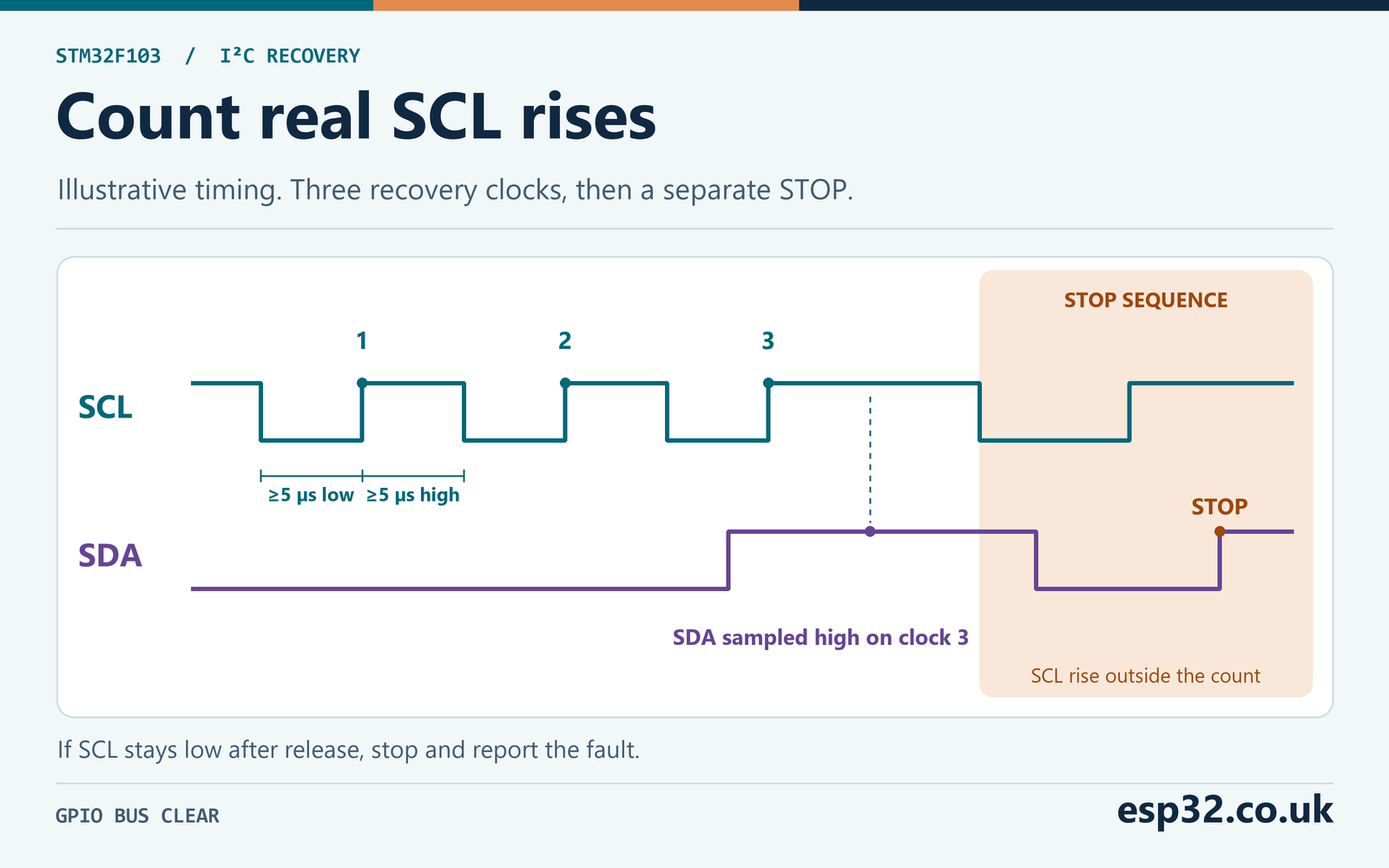
The deliberate STOP has its own SCL transition. After the last recovery pulse, pull SCL low before pulling SDA low, so preparing the STOP does not introduce a new START. Release SCL and verify that it rose. Then release SDA while SCL is high. The SDA rising edge is the STOP. The reported recovery clock count excludes that framing transition. A capture can therefore show three recovery clock rises plus the SCL rise used to prepare STOP. If SDA was high after the initial line release, the ordinary bus-clear path sends neither recovery pulses nor this STOP.
The helper holds low and high for at least a nominal 5 µs after confirming the relevant pin level. In Standard-mode the nominal minimum SCL low and high intervals are 4.7 µs and 4.0 µs, respectively. Waiting for the high input before starting the high hold gives slow edges and bounded stretching time to settle. Software and GPIO polling add overhead, so the GPIO pulse stream is slower than the ideal 100 kHz obtained by dividing one second by a 10 µs cycle. The recovery clocks are generated in software. Once restored, the I²C peripheral resumes the rate configured in the HAL handle.
DWT CYCCNT supplies the microsecond-scale delays. At 72 MHz the minimum hold is 360 cycles and a level wait is about 72,000 cycles, or 1 ms. At 8 MHz those values are 40 and 8,000 cycles. Each wait uses unsigned subtraction, so counter wrap during a short wait is harmless. The routine checks that the cycle counter is available and running. Keep HCLK and DWT settings stable, run in privileged foreground code, and avoid single-stepping the waveform. An interrupt can extend the observed delay or wall-clock timeout. STM32 DWT cycle counter guide
Nine clocks are a recovery attempt, and a target may consume them as the remainder of an interrupted write. Treat the transaction that failed as having an uncertain outcome. A read-only identification or status check is a suitable first verification. A command that clears a flag, commits a setting or advances a device’s address pointer may have had an effect before the fault. Inspect the target state before replaying it. Store enough transaction context to distinguish a safe retry from a duplicate operation.
There are two timing scales to keep in a capture. With no stretch, nine recovery clocks contain at least 90 µs of intentional holds plus GPIO overhead. If the target stretches each release close to the 1 ms wait limit, the same nine observed clocks can take several milliseconds. The initial SCL check and STOP also have their own waits. The loop stops on the first timeout and skips the remaining clocks, so nine times the high wait is an example of a long successful clocking sequence, with additional time spent elsewhere in the API. Track total elapsed time separately if this call is part of a larger recovery deadline.
Consider a trace where SCL rises normally on the first two pulses but stays low after the third release command. The report should show two clocks and I2C_REC_SCL_LOW. There was no third physical rising edge to count. A trace with nine complete SCL pulses and SDA low throughout should return I2C_REC_SDA_LOW. These are useful tests because they show whether the code treats a requested level change as a physical event. A scope makes that distinction visible even if an analyser’s decoder sees no valid I²C frame.
Handle a stale F103 BUSY flag
ES096 section 2.8.7 describes a medium-density STM32F103 condition in which the I²C analogue filter can indicate low while the physical lines are high. The peripheral can then report BUSY and refuse to start. A software reset can clear BUSY while reset is held, yet the stale filter output can reassert BUSY as soon as reset is released. That accounts for a board where reinitialization appears to succeed while the next START never reaches the pins. The relevant evidence is high levels at the MCU and persistent BUSY after reinitialization on an otherwise idle bus. ST STM32F103x8/B device errata ES096
The module first tries a normal restoration after clearing the electrical bus. If BUSY remains set and both pins read high, it disables the peripheral and takes the lines back as released GPIO. It verifies both are high, pulls SDA low and checks it, then pulls SCL low and checks it. Next it releases SCL and verifies high, then releases SDA and verifies high. Those real transitions refresh the line filters. This sequence begins with a START-like SDA transition and ends with a STOP-like transition, so run it only on a known idle single-controller bus.
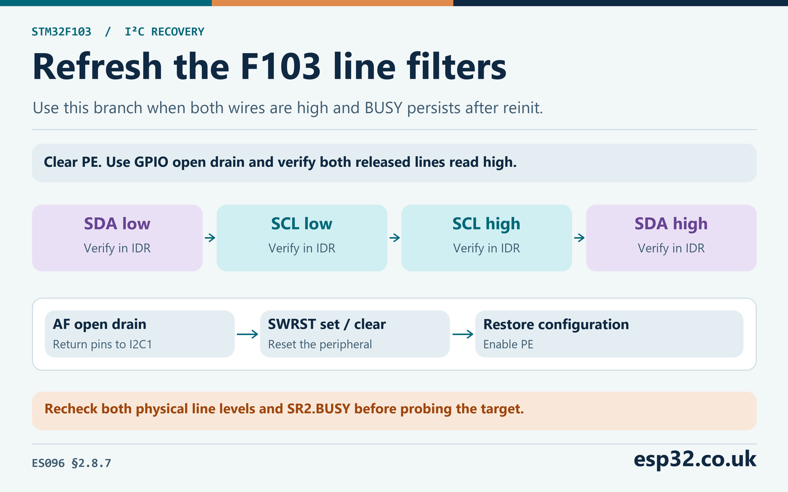
Restore alternate-function open-drain before the software reset. The reviewed CubeF1 v1.1.10 HAL_I2C_Init() disables PE, sets and clears SWRST, restores the clock and address configuration and enables PE. The module uses that path after the GPIO edges, so it does not duplicate SWRST in its own code. When porting to another HAL version or a register-level driver, confirm the actual initialization order. Setting PE without restoring registers cleared by reset can leave incorrect timing or addressing. ST STM32F1 I²C HAL v1.1.10
The report records filter_attempted separately from recovery clocks. A value of one means the code executed that branch, not that the silicon fault was independently proven. Other problems can produce confusing status, especially an active second controller, an unstable supply or noise between reads. If BUSY persists after the one attempt, the function disables I2C1 again, leaves the pins released as GPIO and returns I2C_REC_BUSY. Investigate the cause before changing the policy to repeated toggling. This erratum sequence belongs to the specified F103 device and revision family.
The pin sequence also explains why the return to alternate-function mode matters. While the pins are in GPIO mode, the CPU owns their pull-down behavior. Once they return to AF open drain, the I²C peripheral can drive them again. The lab restores the AF mode with both GPIO outputs released and then lets the HAL reset and configure the peripheral. It samples both pins once more with the peripheral enabled. A line that goes low during the handover fails the restoration. In that case, check whether the pin configuration changed, a target began driving, or the original electrical fault returned.
Add the recovery module to CubeF1
Create an STM32F103C8 project with the default I2C1 mapping, seven-bit addressing and Standard-mode clock speed. Use 100 kHz for the address-only probe in this lab. The module also accepts a lower configured Standard-mode rate. Keep normal HAL tick operation and initialize I2C1 before handing the handle to the recovery function. The module assumes the AFIO, GPIOB and I2C1 clocks from that initialization remain enabled. Disable I2C DMA and interrupt-driven operations for this bench example. STM32CubeIDE and CubeMX setup
Copy i2c_recovery.h to the include folder and i2c_recovery.c to the source folder. Use the Cube-generated I2C1 handle. Its configuration fields remain available for restoration. The routine needs an unlocked handle in the ready state. If your application is stuck with a busy software handle after an asynchronous transfer, first use the driver-specific abort or teardown procedure and wait for completion. The recovery routine avoids rewriting a live transfer’s buffers, callbacks or DMA channel state.
For a register-level check after restoration, compare the APB1 clock, CR2 frequency field, CCR and TRISE with the intended speed. At a nominal 36 MHz PCLK1 and 100 kHz Standard-mode, the simple clock-divider calculation gives CCR = 36,000,000 ÷ (2 × 100,000) = 180. The HAL sets the Standard-mode TRISE field to the clock frequency in MHz plus one, or 37 here. At an 8 MHz PCLK1 the corresponding values are CCR 40 and TRISE 9. These registers describe the peripheral’s timing configuration. The actual physical rise time comes from the bus and still needs measurement.
#ifndef I2C_RECOVERY_H
#define I2C_RECOVERY_H

#include "stm32f1xx_hal.h"

typedef enum {
    I2C_REC_OK, I2C_REC_ARGUMENT, I2C_REC_OWNED, I2C_REC_CLOCK,
    I2C_REC_REMAP, I2C_REC_SCL_LOW, I2C_REC_SDA_LOW,
    I2C_REC_DRIVE, I2C_REC_INIT, I2C_REC_BUSY
} I2cRecoveryStatus;

typedef struct {
    uint16_t before_high;
    uint16_t after_high;
    uint8_t clocks;
    uint8_t busy_before;
    uint8_t filter_attempted;
} I2cRecoveryReport;

/* Blocking foreground, one controller, default I2C1 on PB6/PB7. */
I2cRecoveryStatus I2c_Recover(I2C_HandleTypeDef *bus, I2cRecoveryReport *report);

#endif
#include <stdbool.h>
#include "i2c_recovery.h"
#define SCL GPIO_PIN_6
#define SDA GPIO_PIN_7
#define LINES (SCL | SDA)
static uint16_t high_lines(void)
{
return (uint16_t)(GPIOB->IDR & LINES);
}
static void release(uint16_t pins)
{
GPIOB->BSRR = pins;
}
static void pull_low(uint16_t pins)
{
GPIOB->BSRR = (uint32_t)pins << 16;
}
static void pin_mode(uint32_t mode)
{
GPIO_InitTypeDef gpio = {
.Pin = LINES, .Mode = mode, .Pull = GPIO_NOPULL, .Speed = GPIO_SPEED_FREQ_HIGH
};
HAL_GPIO_Init(GPIOB, &gpio);
}
static void pause_cycles(uint32_t ticks)
{
uint32_t start = DWT->CYCCNT;
while ((uint32_t)(DWT->CYCCNT - start) < ticks) {}
}
static bool await_level(uint16_t pin, bool high, uint32_t hold)
{
uint32_t start = DWT->CYCCNT;
do {
if (((high_lines() & pin) != 0U) == high) {
return true;
}
} while ((uint32_t)(DWT->CYCCNT - start) < 200U * hold);
return false;
}
static void take_gpio(I2C_HandleTypeDef *bus)
{
__HAL_I2C_DISABLE(bus);
release(LINES);
pin_mode(GPIO_MODE_OUTPUT_OD);
}
static I2cRecoveryStatus finish_stop(uint32_t hold)
{
pull_low(SCL);
if (!await_level(SCL, false, hold)) {
return I2C_REC_DRIVE;
}
pull_low(SDA);
if (!await_level(SDA, false, hold)) {
return I2C_REC_DRIVE;
}
pause_cycles(hold);
release(SCL);
if (!await_level(SCL, true, hold)) {
return I2C_REC_SCL_LOW;
}
pause_cycles(hold);
release(SDA);
if (!await_level(SDA, true, hold)) {
return I2C_REC_SDA_LOW;
}
pause_cycles(hold);
return I2C_REC_OK;
}
static I2cRecoveryStatus clear_bus(uint32_t hold, I2cRecoveryReport *report)
{
if (!await_level(SCL, true, hold)) {
return I2C_REC_SCL_LOW;
}
pause_cycles(hold);
while (!(high_lines() & SDA) && report->clocks < 9U) {
pull_low(SCL);
if (!await_level(SCL, false, hold)) {
return I2C_REC_DRIVE;
}
pause_cycles(hold);
release(SCL);
if (!await_level(SCL, true, hold)) {
return I2C_REC_SCL_LOW;
}
++report->clocks;
pause_cycles(hold);
}
if (!(high_lines() & SDA)) {
return I2C_REC_SDA_LOW;
}
return report->clocks ? finish_stop(hold) : I2C_REC_OK;
}
static I2cRecoveryStatus restore_controller(I2C_HandleTypeDef *bus, uint32_t hold)
{
pin_mode(GPIO_MODE_AF_OD);
if (HAL_I2C_Init(bus) != HAL_OK) {
return I2C_REC_INIT;
}
if (!await_level(SCL, true, hold)) {
return I2C_REC_SCL_LOW;
}
if (!await_level(SDA, true, hold)) {
return I2C_REC_SDA_LOW;
}
pause_cycles(hold);
return (bus->Instance->SR2 & I2C_SR2_BUSY) ? I2C_REC_BUSY : I2C_REC_OK;
}
I2cRecoveryStatus I2c_Recover(I2C_HandleTypeDef *bus, I2cRecoveryReport *report)
{
if (!report) {
return I2C_REC_ARGUMENT;
}
*report = (I2cRecoveryReport){0};
if (!bus || bus->Instance != I2C1 || !bus->Init.ClockSpeed || bus->Init.ClockSpeed > 100000U) {
return I2C_REC_ARGUMENT;
}
if (bus->State != HAL_I2C_STATE_READY || bus->Lock != HAL_UNLOCKED) {
return I2C_REC_OWNED;
}
if (AFIO->MAPR & AFIO_MAPR_I2C1_REMAP) {
return I2C_REC_REMAP;
}
uint32_t hclk = HAL_RCC_GetHCLKFreq();
if (hclk < 1000000U || hclk > 72000000U || HAL_RCC_GetPCLK1Freq() < 2000000U) {
return I2C_REC_CLOCK;
}
CoreDebug->DEMCR |= CoreDebug_DEMCR_TRCENA_Msk;
__DSB();
if (DWT->CTRL & DWT_CTRL_NOCYCCNT_Msk) {
return I2C_REC_CLOCK;
}
DWT->CTRL |= DWT_CTRL_CYCCNTENA_Msk;
__DSB();
__ISB();
uint32_t before = DWT->CYCCNT;
__NOP();
__NOP();
if (before == DWT->CYCCNT) {
return I2C_REC_CLOCK;
}
uint32_t hold = ((hclk + 999999U) / 1000000U) * 5U;
report->before_high = high_lines();
report->busy_before = (bus->Instance->SR2 & I2C_SR2_BUSY) != 0U;
take_gpio(bus);
I2cRecoveryStatus status = clear_bus(hold, report);
if (status == I2C_REC_OK) {
status = restore_controller(bus, hold);
}
if (status == I2C_REC_BUSY && high_lines() == LINES) {
/* ES096 section 2.8.7. HAL_I2C_Init performs SWRST after AF restoration. */
report->filter_attempted = 1U;
take_gpio(bus);
pause_cycles(hold);
if (high_lines() != LINES) {
status = (high_lines() & SCL) ? I2C_REC_SDA_LOW : I2C_REC_SCL_LOW;
} else {
pull_low(SDA);
if (!await_level(SDA, false, hold)) {
status = I2C_REC_DRIVE;
} else {
pause_cycles(hold);
status = finish_stop(hold);
}
}
if (status == I2C_REC_OK) {
status = restore_controller(bus, hold);
}
}
if (status != I2C_REC_OK) {
take_gpio(bus);
pause_cycles(hold);
}
report->after_high = high_lines();
return status;
}Add the following include and watch variables in the generated user regions. Put the request check inside the foreground loop. In a debug session, set recovery_request to one and resume normal execution. Use a target with a known address. The example uses a display configured as 0x3C, passed to CubeF1’s HAL in the shifted format 0x3C << 1. Change it for your module and verify its address on a healthy bus first. ST-Link and SWD wiring guide
#include "i2c_recovery.h"

volatile uint32_t recovery_request;
volatile I2cRecoveryStatus recovery_status;
volatile I2cRecoveryReport recovery_report;
volatile HAL_StatusTypeDef probe_status;

/* Run inside the foreground loop after I2C1 initialization. */
if (recovery_request) {
    recovery_request = 0U;
    I2cRecoveryReport sample;
    recovery_status = I2c_Recover(&hi2c1, &sample);
    recovery_report = sample;
    if (recovery_status == I2C_REC_OK) {
        probe_status = HAL_I2C_IsDeviceReady(&hi2c1, 0x3CU << 1, 1U, 10U);
    }
}
Read the report after the loop has serviced the request. The pin fields contain masks, so 0x0040 means SCL high, 0x0080 means SDA high and 0x00C0 means both high. Check the status before interpreting the masks. An argument, ownership, remap or clock guard can return before the hardware snapshots. The address probe runs only on a successful restoration, so a failed attempt can leave a probe value from a prior run. Use the recovery status and the fresh probe together.
An ACK indicates the target responded to its address. It gives no guarantee that the preceding failed operation rolled back or that the application state survived. Follow it with a documented read or an application-level health check. A repeated-START register read can expose separate timing problems that the address probe never exercises. For the affected F103 and operating conditions, check the repeated-START timing entry in ES096 and its recommended remedies before changing the recovery algorithm.
ES096 lists a repeated-START setup-time issue under specific conditions and gives reducing the bus frequency to 88 kHz as one remedy. The address-only test here exercises an ordinary START and STOP. If a register read fails after the address probe passes, capture the repeated START and check the precise erratum conditions. For an affected Standard-mode setup you can try a lower bus rate, such as 50 kHz, and repeat the capture. The peripheral speed and GPIO recovery pulse holds are configured independently, so changing the ordinary bus speed does not alter the nominal 5 µs GPIO holds.
Reproduce the fault and read the capture
Begin with the normal circuit and no forced fault. Confirm both lines high between transactions, then run one recovery request. With a healthy idle bus the report should show zero recovery clocks and the next address should ACK. Save this trace as the baseline. On a logic analyser, label the two lines correctly and configure the decoder to show the seven-bit address. An address displayed as 0x78 by an eight-bit decoder can represent the same on-wire write address as 0x3C in a seven-bit display.
For a controlled persistent-low case, use an open-drain test output or a temporary pull to ground on the short bench bus. Apply it only after confirming the wiring, open-drain configuration and 3.3 V pull-ups. Hold SDA low through the attempt and check that the code emits nine recovery clocks, returns I2C_REC_SDA_LOW and leaves the lines released. Remove the test pull, request recovery again and check the idle levels and address probe. A permanent ground connection cannot demonstrate an early release. Use an open-drain fixture that releases SDA after a known count if you want to test that branch on hardware.
Repeat with SCL held low. The controller should release its own outputs, observe that SCL did not rise, wait out the bounded interval and return I2C_REC_SCL_LOW. It should count zero recovery clocks. If the target is genuinely stretching, SCL may rise before the deadline and the code can continue. A long stretch can be normal for some targets. Set a production wait budget from that target’s data sheet and the application’s latency needs. The lab’s roughly 1 ms value is a deliberate bound for a small bench bus, rather than a universal I²C timing limit.
| Result | Observation to make next |
|---|---|
I2C_REC_OK, address ACK | Verify the application-level target state |
I2C_REC_OK, address NACK | Check the address, power and target readiness |
I2C_REC_SCL_LOW | Scope the released clock and isolate the segment holding it |
I2C_REC_SDA_LOW | Check whether SDA released before the ninth clock or STOP |
I2C_REC_DRIVE | Verify pin mapping and that GPIO open drain can pull down safely |
I2C_REC_BUSY | Check idle voltages, ownership, errata applicability and reinitialization |
I2C_REC_OWNED | Finish or abort the HAL operation before recovery |
I2C_REC_CLOCK, I2C_REC_REMAP, or I2C_REC_INIT | Inspect clocks, DWT, pin routing and Cube HAL setup |
The analogue-filter case is an intermittent silicon condition. Holding an external wire low exercises the electrical fault path and cannot be used as proof that the filter fault occurred. If you do see a real event with both wires high and BUSY set, save the pre-recovery register and line state and capture the workaround. Look for the SDA-low, SCL-low, SCL-high, SDA-high order and then a valid address transaction. A fresh capture is more informative than stepping through the GPIO calls because debugger halts change pulse timing and can interrupt the normal traffic.
Keep a worksheet with the observed pulses, the before and after masks, whether the filter path ran and the probe result. For example, SDA physically held low with an available clock should give an initial mask of 0x0040, nine clocks and the same final mask while the fault remains. With the clamp removed, a second request should return 0x00C0 after restoration and should send no recovery clocks. If the address still NACKs, return to basic wiring and target power. The two results together show that the firmware stopped driving the bus after failure and could restore it after the electrical condition changed.
If a low appears intermittently, trigger on a pulse width longer than the longest legitimate clock stretch you expect, or record a long trace and inspect it around the software error timestamp. Correlate with the target rail if another channel is available. A repeating fault at the same transaction phase suggests a protocol or driver issue. A fault correlated with a supply step or cable movement points elsewhere. Keep the trace from both before and after a change, so a successful retry does not hide an unresolved electrical problem.
To distinguish a missing pull-up from an active sink during a lab fault, inspect the released rising edge as well as its endpoint. A line that starts rising and stops near an intermediate voltage can indicate leakage, a powered-off input or a reference mismatch. A strong clamp holds it near the low plateau without a normal RC rise. If you can safely disconnect the suspected device while powered down, retest the isolated segment with the same pull-ups before reconnecting it. Record both the unloaded and loaded results. Raising the timeout may hide a slow edge from the recovery routine, while the ordinary 100 kHz transfers still violate rise-time limits.
Decide when to retry in the application
Use recovery in response to a diagnosed fault. A single NACK from a known busy target can be part of its ordinary protocol. A repeated transfer timeout, together with physical line or peripheral evidence, is a better reason to take ownership and inspect the bus. Limit the number of attempts and preserve the original HAL error, line snapshots and outcome for diagnosis. A log that records only the final successful retry can hide a device that repeatedly loses synchronization when its power rail dips.
On a system with independently powered targets, consider whether resetting one device can release the segment. A power cycle can also disturb healthy devices and expose powered-off input behavior. Reset or power switching belongs to the application because only it knows the wiring, power domains and the state that must be reloaded. After restoration, verify the target before resuming the normal workload. If the fault follows one detachable branch, keep that branch isolated while confirming the rest of the bus still works.
For a production state machine, separate the failure that triggered recovery from the recovery result and the follow-up transaction. For example, preserve a transmit timeout, record that SCL was held low, and defer the next probe until the target reset or power policy has run. If a target later answers its address, carry the original failure forward for telemetry. Keep a count of recoveries by fault class, and examine the frequency when changing wiring or power. A good bench result is a useful baseline for later comparison under the real workload.
Keep the case distinctions in the test report. A low SCL with zero pulses shows that the routine correctly refused to clock a blocked wire. Nine clocks with SDA still low show that the bounded bus clear was attempted and failed. High lines and a persistent BUSY show a controller-side diagnosis worth investigating. Those observations are actionable even when recovery fails. Together with a capture of the last normal transaction, they let you fix the underlying issue and verify the change with the same bench procedure.