
This esp32PriceAliExpress price.co.uk/ guide builds a Modbus RTU client on an STM32F103 Blue PillPriceAliExpress price. It sends a Read Holding Registers request over two-wire RS-485, releases the bus after the last stop bit, and checks the returned address, function, byte count and CRC before updating the register values. The bench example reads two words from unit 1 and gives you exact bytes to compare with a serial capture.
Use USART1 on PA9 and PA10, a 3.3 V MAX3483AE half-duplex transceiver, and PB1 for direction control. Configure both ends for 9600 baud, eight data bits, even parity and one stop bit. In STM32F1 HAL, that means selecting the 9-bit word length with even parity. The parity bit occupies the last position in the configured word.
What the lab does
The STM32PriceAliExpress price initiates each transaction, so it is the Modbus client and the serial-line master. The device at the other end is the addressed server. Modbus RTU defines the bytes, their timing and the error checks. RS-485 defines the electrical link that carries those bytes. USART1 supplies the serial framing at logic levels and the transceiver translates those signals to and from the differential pair. A working UART alone cannot drive that pair.
The lab uses one client and one server on a short bench link. It implements function 0x03 for a unicast read, allows one transaction at a time, and uses a blocking transmit and a polled receiver. The code accepts ordinary replies and function 0x83 exception replies. You can use the included PC test peer with an automatic-direction USB–RS-485 adapter, or use an existing server with a documented holding register map. Modbus protocol specifications
Have a Blue Pill with a genuine STM32F103C8, a 3.3 V transceiver breakout or circuit, a twisted data pair and a common conductor. Use SWD for flashing and for watching the result, since USART1 is already carrying the Modbus frames. A logic analyser can capture TX, RX and direction on the logic side. Use a suitable differential measurement for the RS-485 pair. ST DS5319 datasheet · Blue Pill pinout · ST-LINK and SWD wiring
Wire USART1 to the RS-485 transceiver
The MAX3483AE operates from 3.3 V and has a separate driver enable and active-low receiver enable. Tie DE and /RE together at PB1. A high level drives the pair and disables the receiver, preventing a local echo. A low level releases the pair and enables the receiver. Add a 10 kΩ pull-down from PB1 to ground so the driver stays disabled while the MCU pin is an input during reset. Put a 100 nF bypass capacitor close to the transceiver supply pins if the board does not already provide one.
| Blue Pill connection | Transceiver connection | Purpose |
|---|---|---|
| PA9, USART1_TX | DI | Logic-level output from STM32 |
| PA10, USART1_RX | RO | Logic-level input to STM32 |
| PB1, push-pull output | DE and /RE tied together | High to send, low to receive |
| 3.3 V | VCC | Transceiver power |
| GND | GND and link Common | Reference conductor on the bench |
| Pull-down from PB1 to GND | 10 kΩ | Holds direction in receive during reset |
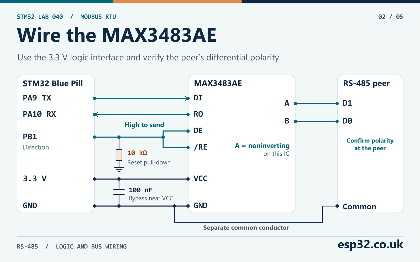
On this IC, A is the noninverting terminal. A is higher than B when the transmitter input is high. Modbus calls the line that is higher for a binary one D1, so this IC’s A connects to D1 and B to D0. The letters on a peer can follow a different convention. Map the peer using its D1 and D0 definitions or its voltage polarity for a binary one, then record how the connector is labelled. This prevents a surprisingly common mismatch between two devices that both print A and B. Analog Devices MAX3483AE family datasheet · Modbus Serial Line Guide V1.02
Use PA10 as an input with a pull-up for this lab. When /RE is high, RO is high impedance. The pull-up keeps the STM32 input at a UART idle level during that time. This pull-up is on the MCU logic input. Any idle bias for the RS-485 network belongs on the differential pair and serves a different purpose. The MAX3483AE receiver has a defined high output on a terminated idle pair with all drivers disabled under its datasheet conditions. Check the peer’s idle receiver requirements before deciding whether the bus needs bias.
For a typical 120 Ω twisted-pair bench cable with resistor-only termination, place one matched terminator across D1 and D0 at each physical end. Check whether the adapter or breakout already fits one. Two 120 Ω resistors in parallel read about 60 Ω with power off and other paths absent. The Modbus serial-line guide gives termination options, including 150 Ω resistors and a series resistor-capacitor arrangement for a polarised line. Use the design for the installed cable and equipment. In a multi-node network, put termination at the trunk ends and keep stubs short. If the system needs line polarisation, fit it at one defined location.
The bench connection uses a shared signal reference. RS-485 receivers still have a common-mode range, and a large difference between equipment ground potentials can exceed it. For a link beyond the local bench, use the equipment’s grounding and isolation design. Keep the pair on the transceiver bus terminals. PA9 and PA10 are only on the local logic side. A USB-to-TTL serial adapter belongs on that side and cannot substitute for the RS-485 peer.
Before connecting the peer, check the receive idle state with the Blue Pill powered. PB1 should be low and PA10 should be high. Once the firmware starts a request, PB1 should go high and a differential signal should appear at the transceiver. For the polarity check, compare the differential measurement V(D1) − V(D0) with PA9 while the client is driving. During a logic one on PA9 the difference should be positive. This distinguishes reversed line labels from a driver that never enabled. Measure the peer’s transmitter separately if the request looks good but the reply decodes inverted.
A useful bench drawing labels the transceiver chip terminals A and B and labels the cable D1 and D0. Write both sets down when you test a different adapter. The same cable colour can stand for D1 throughout the setup even if the labels printed at the ends disagree. Leave the debugger and analyser ground connections on the logic reference when looking at PA9, PA10 and PB1. A differential probe or a suitable receiver is the appropriate way to observe the pair.
Set up USART1 and the microsecond timer
Create an STM32F103C8 project and retain Serial Wire debug. Enable USART1 in asynchronous transmit and receive with default pin mapping. Configure PB1 as a push-pull output and set its initial level low. Keep PA9 as alternate-function push-pull and PA10 as an input with pull-up. This module owns USART1 during the exchange. Leave UART interrupt reception, DMA and flow control disabled and route console output to a separate peripheral if the application uses logging. STM32CubeMX and CubeIDE setup · STM32 UART and HAL guide
| Setting | STM32F103 configuration |
|---|---|
| USART1 baud rate | 9600 |
| Wire format | 8E1 |
| HAL word length | UART_WORDLENGTH_9B |
| HAL parity | UART_PARITY_EVEN |
| HAL stop bits | UART_STOPBITS_1 |
| Flow control | None |
| TIM2 source | Internal clock, upcounting |
| TIM2 counter rate | 1 MHz |
| TIM2 auto-reload | 65,535 |
On this STM32F1 USART, parity replaces the most significant bit of the configured word. With word length 9 and parity enabled, eight positions remain for payload. With word length 8 and parity enabled, only seven positions remain for payload. The address byte and function byte might look plausible with the wrong setting because their top bit is zero. Test with a value above 0x7F in the payload, such as the AB CD word in this lab. The HAL sends the byte array directly when 9-bit mode uses parity. Its special 16-bit element handling is for 9-bit mode without parity. ST RM0008 reference manual · ST STM32F1 UART HAL v1.1.10
For a minimal clock tree, use nominal 8 MHz HSI as SYSCLK with both APB prescalers set to one. TIM2 then takes 8 MHz and PSC = 7 divides it to one tick per microsecond. The USART1 baud register at nominal 8 MHz and 9600 baud is 0x0341, which corresponds to a nominal wire rate of about 9603.84 baud before oscillator tolerance. If the project uses 72 MHz SYSCLK with APB1 divided by two, PCLK1 is 36 MHz and the TIM2 input is 72 MHz because the F1 doubles the timer clock in that configuration. Use PSC = 71 in that clock tree. USART1 is on APB2, so its baud generator follows PCLK2. STM32 timers and prescaler calculations
Start TIM2 with HAL_TIM_Base_Start() and leave it running. The receive loop uses modular subtraction on the low 16 bits for intervals much shorter than the 65.536 ms rollover. SysTick supplies the separate millisecond limit for the whole transaction, which may span several timer wraps. The software checks the configured baud, UART format and timer running state. Check the timer input frequency and prescaler in the generated project, since a running timer alone does not establish that each count equals one microsecond.
Work out the RTU timing before sending
At 9600 baud and 8E1, one character is 11 bits. That is one start bit, eight data bits, one parity bit and one stop bit. A bit lasts about 104.167 µs, and a character lasts about 1,145.833 µs. For this baud rate, the serial-line specification uses character-based timing. Its inter-character limit is 1.5 character times and its inter-frame silence is at least 3.5. Above 19,200 baud, the guide recommends fixed intervals of 750 µs and 1.750 ms respectively. The code below is specific to 9600 baud.
| Quantity | Calculation | Nominal value |
|---|---|---|
| One character | 11 ÷ 9,600 | 1,145.833 µs |
| Maximum intra-frame wire silence | 1.5 × character time | 1,718.750 µs |
| Minimum inter-frame wire silence | 3.5 × character time | 4,010.417 µs |
| Eight-byte request duration | 8 × character time | 9.167 ms |
| Nine-byte normal reply duration | 9 × character time | 10.313 ms |
| Longest in-frame RXNE spacing used by the lab | Round up 2.5 × character time | 2,865 µs |
| Polling guard to close a reply | Round up 4.5 × character time | 5,157 µs |
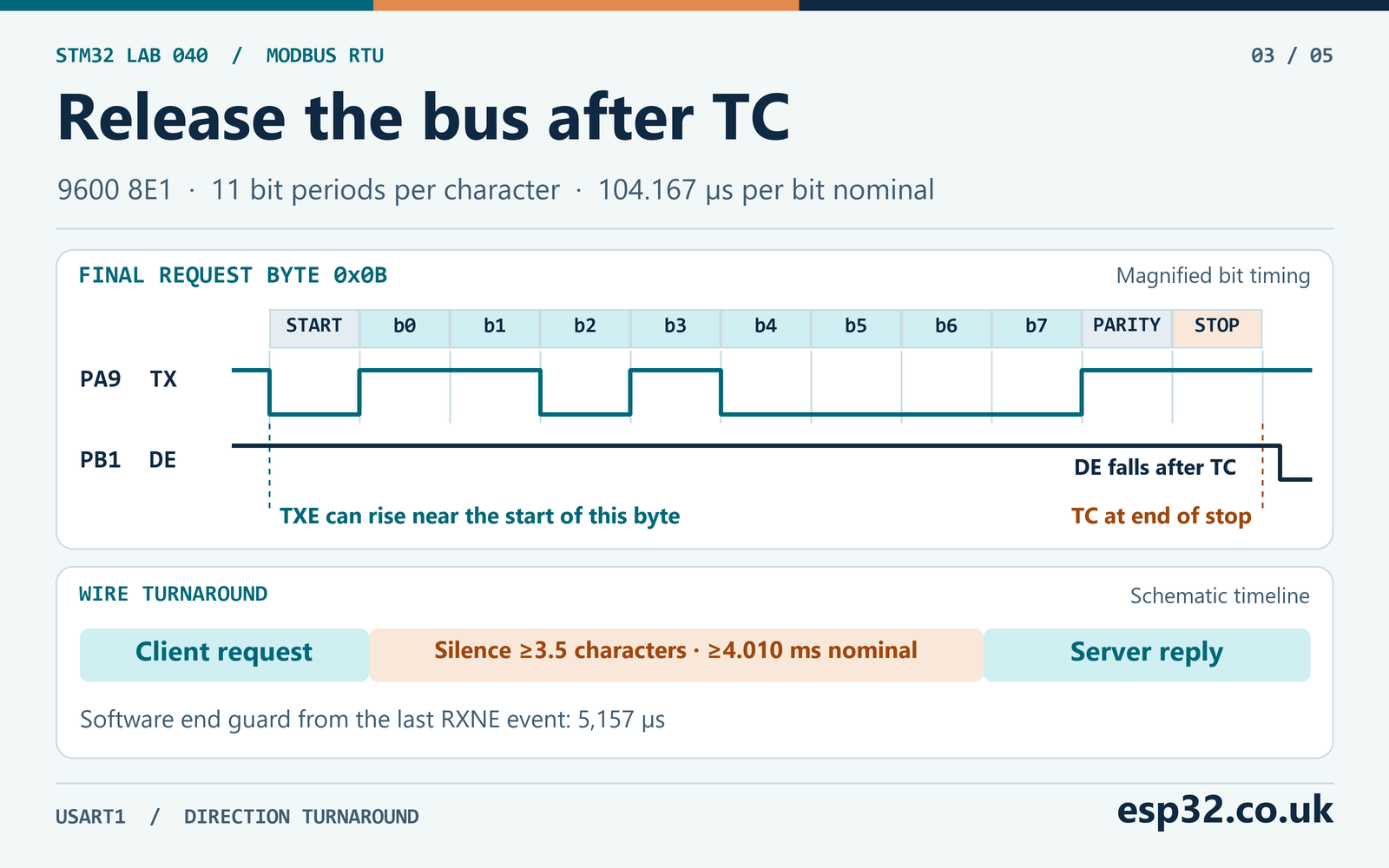
The last two rows are software thresholds derived for sampling at receive-ready events. Two successive RXNE events are approximately one character time apart with zero wire gap. To check a 1.5-character wire gap using the distance between the events, the code adds the duration of the second character. When deciding that the frame is over, it gives a potential character that started just before the 3.5-character boundary time to finish and raise RXNE. This explains why the close timer in the code is longer than the required silence on the wire. USART timing, the peer’s baud accuracy and polling latency affect the timestamp approximation. Use a scope to judge traffic at the boundary.
The lab checks for a quiet bus before taking control. While listening, it discards old bytes or error indications and restarts its quiet guard each time it sees one. A steady stream of activity reaches a 35 ms budget and returns MB_BUS_BUSY. This covers the controlled bench with a single master. It is not arbitration between two independent masters, and a quiet line cannot prove that a remote device will never send a delayed reply.
Drop DE after the stop bit
The transmit-data-empty flag TXE indicates that the data register can take the next byte. On the final byte it can set while the shift register is still sending that byte. Use TC to identify the end of the transmission. The audited blocking HAL_UART_Transmit() implementation waits for TC before returning HAL_OK. Set PB1 high before calling it, allow a five-tick driver enable guard, then lower PB1 immediately after the call. For this wired topology the receiver is enabled while the driver is disabled, so the part stays out of its shutdown mode. The normal enable limit for the MAX3483AE is 2.5 µs under its specified test load.
On a timeout the code drops DE to avoid keeping the bus driven. A timeout can truncate a request and is reported as a failed transaction. If you later switch to DMA or interrupt-driven transmission, review the corresponding HAL callback path and the hardware TC flag before reusing the direction logic. A DMA completion event can mean the final byte reached the UART data register, with serial shifting still in progress. The STM32F103 USART lacks the programmable driver-enable hardware found on some later STM32 USARTs, so this lab uses GPIO.
Estimate a poll cycle from the wire
If a server begins as soon as the minimum 3.5-character interval has passed, the exchange takes about 9.167 ms for the request, 4.010 ms of silence and 10.313 ms for the reply. Allowing another 4.010 ms before the next request puts the theoretical request-to-request floor near 27.5 ms. Real polling includes server processing and software guards. The PC helper deliberately waits 10 ms after its serial read, and a USB adapter and host scheduler can add more delay. The lab also waits one second between attempts to make it easy to inspect the exchange.
For a fleet of devices, use the measured response time of each address. Sum the request, turnaround, reply and required idle time for each poll. Include timeout slots for devices that fail to respond, since those can dominate a scan. An application that needs predictable latency should record measured turnaround separately from the total transaction duration. If a busy server’s first byte appears just before the timeout, the remaining bytes and the software closing guard still need time inside the configured budget.
Follow the register request and reply byte by byte
Function 0x03 reads a contiguous block of holding registers. The request contains the server address, function code, a two-byte starting address, a two-byte quantity and the two CRC bytes. The register address in the frame is zero based. A manual that labels the first holding register 40001 often means wire offset zero. Some manuals and tools already display wire offsets. Use the device register map and check the actual request bytes before subtracting an address base.
| Request field | Bytes | Meaning |
|---|---|---|
| Unit | 01 | Server address 1 |
| Function | 03 | Read Holding Registers |
| Starting address | 00 00 | First wire offset |
| Quantity | 00 02 | Two 16-bit registers |
| CRC | C4 0B | Numeric CRC 0x0BC4, low byte first |
Compare the complete request 01 03 00 00 00 02 C4 0B with the eight decoded bytes on PA9 before checking the server.
The normal response is 01 03 04 12 34 AB CD 00 20. The first two bytes identify the responding unit and function. Byte 04 counts the four following register data bytes. The words are 0x1234 and 0xABCD. The numeric CRC is 0x2000, so the wire carries 00 20 at the end. The leading zero is significant. Register bytes within each word are high first. The CRC bytes at the end are low first.
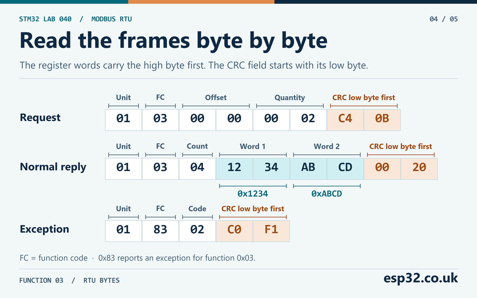
The short reply 01 83 02 C0 F1 is a valid exception. The high bit in 0x83 marks the exception for function 0x03, and 0x02 means Illegal Data Address. The PC peer sends this reply for the alternate request 01 03 00 02 00 02 65 CB. Try that request after the normal read succeeds. The same serial link, address and CRC checks apply to an exception. It can confirm that the electrical connection and frame decoding work even when the server rejects the requested register range. Modbus Application Protocol V1.1b3
This function accepts one to 125 registers. The normal reply has three header bytes, two bytes per register and two CRC bytes. A request for 125 registers can therefore produce a 255-byte reply with a byte count of 250. The code sizes its buffer for that reply and checks the quantity before assembling the request. Allocate a destination with at least as many elements as the requested count. For the first bench run, two values suffice.
The register data are unsigned 16-bit words at this stage. A server might define them as signed values, counters, scaled measurements or parts of a wider quantity. Apply those meanings only after verifying the response. When a vendor splits a 32-bit value across two registers, the word order comes from its device map. The high-byte-first rule within each register gives you no information about which of the two registers is the high word.
It helps to maintain a small mapping table for each device, with the unit number, function, wire offset, register count and interpretation. For example, a manual might put a counter at holding registers 40001 and 40002 and specify the low word first. The wire request for those two positions would start at zero. After decoding two 16-bit words in the order returned, the application would combine the second as the high word and the first as the low word. A value in the input-register table would normally use function 0x04, even if its offset was also zero. This lab only sends function 0x03.
Check CRC-16 and preserve the previous good data
The RTU CRC starts at 0xFFFF. Each input byte is XORed into the running value and processed with eight right shifts. When the low bit is set, the shift is followed by XOR with the reflected polynomial 0xA001. For the ASCII digits 123456789 the expected numeric value is 0x4B37. The CRC covers the unit, function and data fields, up to but excluding the CRC itself. It operates on binary bytes, including any 00 values. STM32 hardware CRC32 and checksum byte order
A scope’s UART decoder can show plausible bytes even when the configured parity is wrong. That is one reason to reject UART errors before calculating CRC. CRC also does not identify who sent the frame, so the parser checks the unit and function after a good checksum. It verifies the total length and the byte-count field before writing any destination value. An exception writes only the exception output, and an unsuccessful read leaves the previous register data intact.
The Modbus checksum is a different polynomial and width from the STM32F103’s fixed CRC32 peripheral. This example computes the 16-bit value in software. For a separate check, feed the six request bytes 01 03 00 00 00 02 into a CRC-16/MODBUS calculator and expect 0x0BC4. Then send the bytes C4 0B. Comparing the number alone does not verify the wire order.
Add the frame codec and the Blue Pill transport
Put mb_rtu.h and mb_bluepill.h in the include path and add the corresponding C files to the project. The frame codec depends on the C standard headers. The Blue Pill transport uses STM32F1 HAL for setup, direction control and transmit. It reads the USART status and data registers in the receive loop because the timing and error checks need the receive event and its status together.
#ifndef MB_RTU_H
#define MB_RTU_H

#include <stddef.h>
#include <stdint.h>

enum { MB_REQUEST_BYTES = 8, MB_MAX_REGS = 125, MB_MAX_REPLY_BYTES = 255 };

typedef enum {
    MB_OK, MB_BAD_ARGUMENT, MB_BAD_CONFIG, MB_BUS_BUSY, MB_TX_FAILED,
    MB_TIMEOUT, MB_UART_ERROR, MB_GAP, MB_FRAME, MB_CRC, MB_EXCEPTION
} MbResult;

uint16_t Mb_Crc(const uint8_t *bytes, size_t length);
MbResult Mb_BuildRead(uint8_t unit, uint16_t first, uint16_t count,
                      uint8_t request[MB_REQUEST_BYTES]);
MbResult Mb_ParseRead(const uint8_t *reply, size_t length, uint8_t unit,
                      uint16_t count, uint16_t *values, uint8_t *exception);

#endif
#include "mb_rtu.h"
uint16_t Mb_Crc(const uint8_t *bytes, size_t length)
{
uint16_t crc = 0xFFFFU;
for (size_t i = 0; i < length; ++i) {
crc ^= bytes[i];
for (unsigned bit = 0; bit < 8; ++bit) {
uint16_t feedback = (crc & 1U) ? 0xA001U : 0U;
crc = (uint16_t)((crc >> 1) ^ feedback);
}
}
return crc;
}
MbResult Mb_BuildRead(uint8_t unit, uint16_t first, uint16_t count,
uint8_t request[MB_REQUEST_BYTES])
{
if (!request || !unit || unit > 247U || !count || count > MB_MAX_REGS ||
(uint32_t)first + count > 65536U) {
return MB_BAD_ARGUMENT;
}
request[0] = unit;
request[1] = 0x03;
request[2] = (uint8_t)(first >> 8);
request[3] = (uint8_t)first;
request[4] = (uint8_t)(count >> 8);
request[5] = (uint8_t)count;
uint16_t crc = Mb_Crc(request, 6);
request[6] = (uint8_t)crc;
request[7] = (uint8_t)(crc >> 8);
return MB_OK;
}
MbResult Mb_ParseRead(const uint8_t *reply, size_t length, uint8_t unit,
uint16_t count, uint16_t *values, uint8_t *exception)
{
if (!reply || !values || !exception || !unit || unit > 247U ||
!count || count > MB_MAX_REGS) {
return MB_BAD_ARGUMENT;
}
*exception = 0;
if (length < 5U || length > MB_MAX_REPLY_BYTES) {
return MB_FRAME;
}
uint16_t wire_crc = (uint16_t)(((uint16_t)reply[length - 1U] << 8) |
reply[length - 2U]);
if (Mb_Crc(reply, length - 2U) != wire_crc) {
return MB_CRC;
}
if (reply[0] != unit) {
return MB_FRAME;
}
if (reply[1] == 0x83U && length == 5U) {
*exception = reply[2];
return MB_EXCEPTION;
}
if (reply[1] != 0x03U || length != 5U + 2U * count || reply[2] != 2U * count) {
return MB_FRAME;
}
for (uint16_t i = 0; i < count; ++i) {
values[i] = (uint16_t)(((uint16_t)reply[3U + 2U * i] << 8) | reply[4U + 2U * i]);
}
return MB_OK;
}#ifndef MB_BLUEPILL_H
#define MB_BLUEPILL_H
#include "mb_rtu.h"
#include "stm32f1xx_hal.h"
MbResult Mb_ReadHolding(UART_HandleTypeDef *uart, TIM_HandleTypeDef *timer,
uint8_t unit, uint16_t first, uint16_t count,
uint16_t *values, uint8_t *exception);
#endif#include "mb_bluepill.h"
enum {
RX_ERRORS = USART_SR_PE | USART_SR_FE | USART_SR_NE | USART_SR_ORE,
RX_EVENTS = USART_SR_RXNE | USART_SR_ORE, /* Inspect PE after RXNE. */
INTERCHAR_US = 2865, FRAME_END_US = 5157,
IDLE_MS = 35, TX_MS = 30, RESPONSE_MS = 500
};
static uint16_t counter(TIM_HandleTypeDef *timer)
{
return (uint16_t)__HAL_TIM_GET_COUNTER(timer);
}
static uint16_t elapsed(uint16_t now, uint16_t then)
{
return (uint16_t)(now - then);
}
static MbResult wait_idle(USART_TypeDef *port, TIM_HandleTypeDef *timer)
{
uint32_t start_ms = HAL_GetTick();
uint16_t last = counter(timer);
while ((uint32_t)(HAL_GetTick() - start_ms) < IDLE_MS) {
uint32_t status = port->SR;
if (status & RX_EVENTS) {
(void)port->DR;
last = counter(timer);
} else if (elapsed(counter(timer), last) >= FRAME_END_US) {
return MB_OK;
}
}
return MB_BUS_BUSY;
}
static MbResult receive(USART_TypeDef *port, TIM_HandleTypeDef *timer,
uint8_t reply[MB_MAX_REPLY_BYTES], size_t *length)
{
uint32_t start_ms = HAL_GetTick();
uint16_t last = 0;
while ((uint32_t)(HAL_GetTick() - start_ms) < RESPONSE_MS) {
uint32_t status = port->SR;
if (status & RX_EVENTS) {
uint8_t byte = (uint8_t)port->DR;
uint16_t now = counter(timer);
if (status & RX_ERRORS) {
return MB_UART_ERROR;
}
if (*length != 0U && elapsed(now, last) > INTERCHAR_US) {
return MB_GAP;
}
if (*length == MB_MAX_REPLY_BYTES) {
return MB_FRAME;
}
reply[(*length)++] = byte;
last = now;
} else if (*length != 0U && elapsed(counter(timer), last) >= FRAME_END_US) {
return MB_OK;
}
}
return MB_TIMEOUT;
}
MbResult Mb_ReadHolding(UART_HandleTypeDef *uart, TIM_HandleTypeDef *timer,
uint8_t unit, uint16_t first, uint16_t count,
uint16_t *values, uint8_t *exception)
{
if (!uart || !timer || !values || !exception) {
return MB_BAD_ARGUMENT;
}
*exception = 0;
if (uart->Instance != USART1 || uart->Init.BaudRate != 9600U ||
uart->Init.WordLength != UART_WORDLENGTH_9B || uart->Init.Parity != UART_PARITY_EVEN ||
uart->Init.StopBits != UART_STOPBITS_1 || uart->Init.Mode != UART_MODE_TX_RX ||
uart->Init.HwFlowCtl != UART_HWCONTROL_NONE || uart->gState != HAL_UART_STATE_READY ||
timer->Instance != TIM2 || timer->Instance->ARR != 65535U ||
!(timer->Instance->CR1 & TIM_CR1_CEN)) {
return MB_BAD_CONFIG;
}
uint8_t request[MB_REQUEST_BYTES];
MbResult result = Mb_BuildRead(unit, first, count, request);
if (result != MB_OK) {
return result;
}
HAL_GPIO_WritePin(GPIOB, GPIO_PIN_1, GPIO_PIN_RESET);
result = wait_idle(uart->Instance, timer);
if (result != MB_OK) {
return result;
}
HAL_GPIO_WritePin(GPIOB, GPIO_PIN_1, GPIO_PIN_SET);
uint16_t enabled = counter(timer);
while (elapsed(counter(timer), enabled) < 5U) {}
HAL_StatusTypeDef tx = HAL_UART_Transmit(uart, request, MB_REQUEST_BYTES, TX_MS);
HAL_GPIO_WritePin(GPIOB, GPIO_PIN_1, GPIO_PIN_RESET);
if (tx != HAL_OK) {
return MB_TX_FAILED;
}
uint8_t reply[MB_MAX_REPLY_BYTES];
size_t length = 0;
result = receive(uart->Instance, timer, reply, &length);
if (result != MB_OK) {
return result;
}
return Mb_ParseRead(reply, length, unit, count, values, exception);
}The F1 clears several receive errors by reading SR followed by DR. The receive loop takes a status snapshot, then reads the data register for RXNE or overrun. It checks parity on the same snapshot instead of clearing an early PE indication on its own. ST’s medium-density errata notes that parity can signal before RXNE and that the UART IDLE flag can miss an idle frame under some clock differences. This lab times received bytes with TIM2 and leaves USART1 interrupt and DMA reception disabled. ST ES096 device errata
Use one foreground caller and keep SysTick running. At 9600 baud a new character can arrive roughly every 1.146 ms. An interrupt or breakpoint that delays the receive loop by longer than this can cause an overrun or make the software timestamps inaccurate. The blocking example is appropriate for an otherwise quiet bench application. A busy system needs a dedicated receive path, often DMA or interrupts with a separately managed gap timer, and measurements under its worst interrupt load.
Keep the two software time bases distinct when you debug. The timer counter supplies the short interval after the last received character, and unsigned subtraction handles a single rollover during that interval. The millisecond tick covers the whole receive budget. If you stop TIM2 or repurpose its prescaler, the fine timing changes even when the millisecond timeout still looks right. If you stop SysTick, the overall timeout cannot make progress. Check both clocks after changing the clock tree, using a different low-power mode or moving the module into a larger project.
Run the two-register bench exchange
Start the timer after the generated peripheral initialisation. Put the include and watch declarations in the appropriate CubeMX user regions. Insert the remaining statements in the corresponding startup and loop regions. Call Error_Handler() if the timer fails to start. The two local result words are copied to the volatile watch only after the parser reports a successful read.
/* Include and declarations at file scope */
#include "mb_bluepill.h"
volatile uint16_t mb_watch[2];
volatile uint8_t mb_exception;
volatile MbResult mb_result;

/* After GPIO, USART1 and TIM2 initialisation */
if (HAL_TIM_Base_Start(&htim2) != HAL_OK) {
    Error_Handler();
}

/* Inside the main loop */
uint16_t values[2];
uint8_t exception;
MbResult result = Mb_ReadHolding(&huart1, &htim2, 1, 0, 2, values, &exception);
if (result == MB_OK) {
    mb_watch[0] = values[0];
    mb_watch[1] = values[1];
}
mb_exception = exception;
mb_result = result;
HAL_Delay(1000U);
On the PC, close other programs that have the adapter’s serial port open. With pySerial installed, run python bench_peer.py COM7 from the extracted package, substituting your adapter’s port. The helper uses 9600 8E1 and recognises the two exact eight-byte requests above. It waits 10 ms after receiving a complete request before sending the reply. The adapter handles direction automatically. This helper assumes a clean two-node link and the two known requests, so start it before the MCU and restart it after injecting malformed traffic. pySerial port settings
Flash the firmware over SWD and let it run. The peer should print the two frame byte strings and the debugger should show MB_OK, mb_watch[0] = 0x1234 and mb_watch[1] = 0xABCD. Inspect the result after a complete transaction rather than stepping through the live receive loop. If you change the starting offset from zero to two with the test peer connected, expect MB_EXCEPTION and mb_exception = 0x02. The watch retains the last two accepted words. With an actual field device, replace the unit address, starting offset and count with a safe documented read.
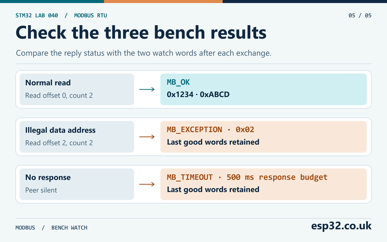
Next stop the peer and let the client finish one attempt. It should return MB_TIMEOUT after its 500 ms response budget. That budget covers the whole reply and the end guard. A maximum-length 255-byte reply at this rate takes about 292.2 ms on the wire with no intra-frame gaps, so the server’s processing delay also has to fit inside the budget. Check the connected device’s worst response time before changing the request count or poll period. Modbus RTU has no transaction ID to distinguish a stale reply from a new request for the same unit, function and quantity.
Diagnose a silent bus or bad reply
Watch PA9, PA10 and PB1 together on the logic side. Trigger on the PB1 rising edge. PA9 should stay high briefly while the driver is enabled, then send the eight bytes as a continuous UART frame. PB1 should stay high through the final stop bit and then go low before the peer starts to drive. Check PA10 after the direction change. If you can see the reply on the differential pair but PA10 stays high, inspect /RE, the local polarity and RO continuity.
| Result or symptom | First check |
|---|---|
MB_BAD_CONFIG | USART1 9600 9-bit plus even parity, TIM2 started with period 65,535 |
MB_BUS_BUSY | Idle RO level, stale traffic, bias and polarity |
MB_TX_FAILED | HAL return, USART clock, SysTick and transmitter enable |
MB_TIMEOUT | Unit address, server serial settings, D1/D0 and response delay |
MB_UART_ERROR | Parity, stop bits, noise, line polarity and CPU stalls |
MB_GAP | Wire gaps between bytes and timing of the receive polling loop |
MB_FRAME | Address, function, byte count and received length |
MB_CRC | Compare the raw bytes and the last two bytes in wire order |
MB_EXCEPTION with 0x02 | Device register map, zero-based starting offset and quantity |
If an occasional failure appears only after enabling a debugger console, make sure it does not share USART1 or keep the core halted during a transaction. If the same wiring works with short jumpers but fails with a cable, check end termination, the reference conductor and the actual line waveform. A ring or reflection can be visible at the far end even when the MCU-side TX signal looks clean. If multiple receivers are attached, inspect each tap and measure again with the final cable layout.
For a corrupted-frame test, change one data byte in the test peer’s normal response and leave the original CRC bytes in place. A response with the right timing and address should yield MB_CRC without changing the watched registers. If the firmware instead reports a UART error or gap, fix that lower-layer problem first. Restore the known frame before trying different starting offsets.
To isolate a timing failure, measure the start-to-start interval between two consecutive reply bytes on PA10. Subtract one character time to estimate the wire silence. With a continuous reply the start-to-start interval should be close to 1.146 ms. With a four-millisecond delay between the two receive events, the implied silence is about 2.85 ms and the client should reject the frame. Use a generator that can control serial timing for that test. A host that sends separate USB writes may produce different gaps on each run.
Also capture the last byte of the request and compare its decoded stop-bit boundary with PB1. The stop bit can share the same logic level as the preceding bit, so there may be no edge at its start. Count the bit periods from the last start bit or use the analyser’s character boundary. A too-early DE transition can leave the last few bits to the idle bias. It may appear to work if the released line happens to decode as the expected high bits. Verify the timing even when the request CRC passes on the peer.
Once the known exchange works, repeat it while collecting counts for each result. A growing CRC count with clean UART status points toward a different problem from repeated framing and parity errors. An increasing busy count before transmission can indicate that the receiver is seeing noise on an idle pair or that another station is driving. Count valid exception responses separately from timeouts. An exception came from a responding server with a valid frame, whereas a timeout can come from a silent device, a disconnected pair or a reply that never reached a complete frame before the budget expired.
Why does a valid CRC still produce a frame error?
The receiver is waiting for the reply to one particular unicast request. A valid CRC can belong to a different unit, a different function or a reply carrying a different number of registers. The parser rejects those before copying register values. Verify the unit number, function and request count against the capture, then look at the byte count the server returned. If the server reports an exception, the code stores the exception byte separately so the application can decide whether to fix its register map or retry.
Can I connect several devices?
The bus can have one client and multiple uniquely addressed servers. A request selects one server, and only that server should answer a unicast read. The bench loop issues one request at a time. For a multi-device poller, choose response deadlines from the devices’ specifications, wait for quiet after errors and handle late replies before issuing another transaction. Fit terminators only at the physical ends and account for the transceivers’ loading and bias.
Can I reuse the code at another baud rate?
The frame codec is independent of the UART rate. For the transport, change the serial configuration on both ends and recalculate the timing constants for the actual character length and timer rate. The serial-line guide recommends different timing above 19,200 baud. A faster rate also shortens the CPU’s window to read DR before the next byte arrives. Measure the final stop bit, the DE transition and the receive service latency after any change.