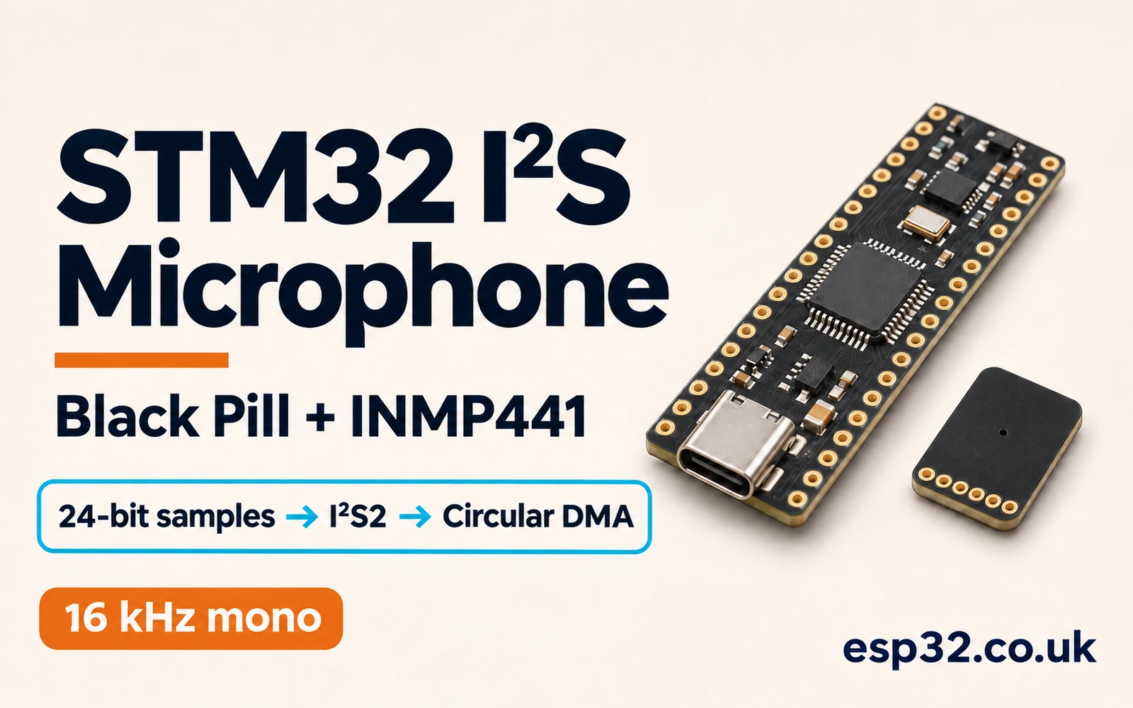
An STM32F411PriceAliExpress price Black PillPriceAliExpress price can capture a digital microphone directly over I²S. Connect the INMP441 to I²S2, let the STM32PriceAliExpress price generate the clocks, and use circular DMA to move the incoming samples into SRAM. The lab in this esp32.co.uk/ guide gives you a 16 kHz mono level monitor. It also gives you a scope target, a DMA layout and a signed sample test so you can isolate a problem before sending any audio to a PC.
Use PB13 for the bit clock, PB12 for word select and PB15 for microphone data. Set I²S2 to Philips master receive, with 24 data bits in each 32-bit channel slot, and set DMA1 Stream 3, Channel 0 to circular halfword transfers. The microphone occupies the left slot when its L/R input is low. The bus still carries two slots per frame.
What this lab captures
The microphone contains its own converter and sends signed digital samples. The STM32 does not sample an analogue voltage in this circuit. I²S supplies a clock and a channel marker, the peripheral assembles the incoming bits and DMA copies its receive register into RAM. The firmware extracts one signed 24-bit sample per stereo frame and publishes the minimum, maximum and mean of each 128-sample block.
The Black Pill name covers several boards. This example targets the STM32F411CE in the 48-pin package. Read the MCU marking and select the matching part in CubeMX. A visually similar STM32F401 board and an STM32F103 Blue Pill need their own peripheral, pin and clock checks. Use the board guide to locate the header pins, then use the F411 datasheet for their alternate functions. STM32F411 Black Pill pinout · STM32F411 datasheet
| Term | Meaning in this lab |
|---|---|
| Sample | One signed 24-bit microphone measurement |
| Channel slot | One 32-clock interval assigned to left or right |
| Stereo frame | One left slot followed by one right slot |
| Word select (WS) | The channel timing signal. One full period is one stereo frame |
| Bit clock (SCK) | The clock that shifts serial bits. Also labelled BCLK or CK |
| DMA halfword | One 16-bit transfer from the I²S data register to memory |
You need an F411 Black Pill, an INMP441 breakout, an SWD programmer and short jumper wires. A scope or logic analyser makes first bring-up much faster. The sample monitor runs under the debugger and does not need a USB audio driver, UART wiring or a filesystem. Use the programmer for SWD and make sure its reference voltage, ground and signal connections match the board and the programmer model. ST-LINK and SWD wiring
Wire the INMP441 to I²S2
Both devices operate with 3.3 V signalling in this lab. Turn the board off before wiring. Connect the breakout to the board’s 3.3 V rail and common ground, and verify the breakout pin labels before applying power. Some boards call the clock pin SCK, others call it BCLK. Use the board header marked PB13 regardless of how the breakout names the other end. Leave PB14 out of this circuit. SPI2 uses it for MISO in SPI mode, but the main I²S2 data signal in this configuration is PB15.
| Black Pill signal | INMP441 breakout | Direction and purpose |
|---|---|---|
| PB13, AF5 I²S2_CK | SCK | STM32 to microphone, bit clock |
| PB12, AF5 I²S2_WS | WS | STM32 to microphone, left and right slot timing |
| PB15, AF5 I²S2_SD | SD | Microphone to STM32, serial sample data |
| 3.3 V | VDD | Breakout power |
| GND | GND | Common return and logic reference |
| GND | L/R | Select left slot |
| 3.3 V, if pin is exposed | CHIPEN | Enable the microphone |
| GND through 100 kΩ | SD | Weak pull-down on the shared data signal |
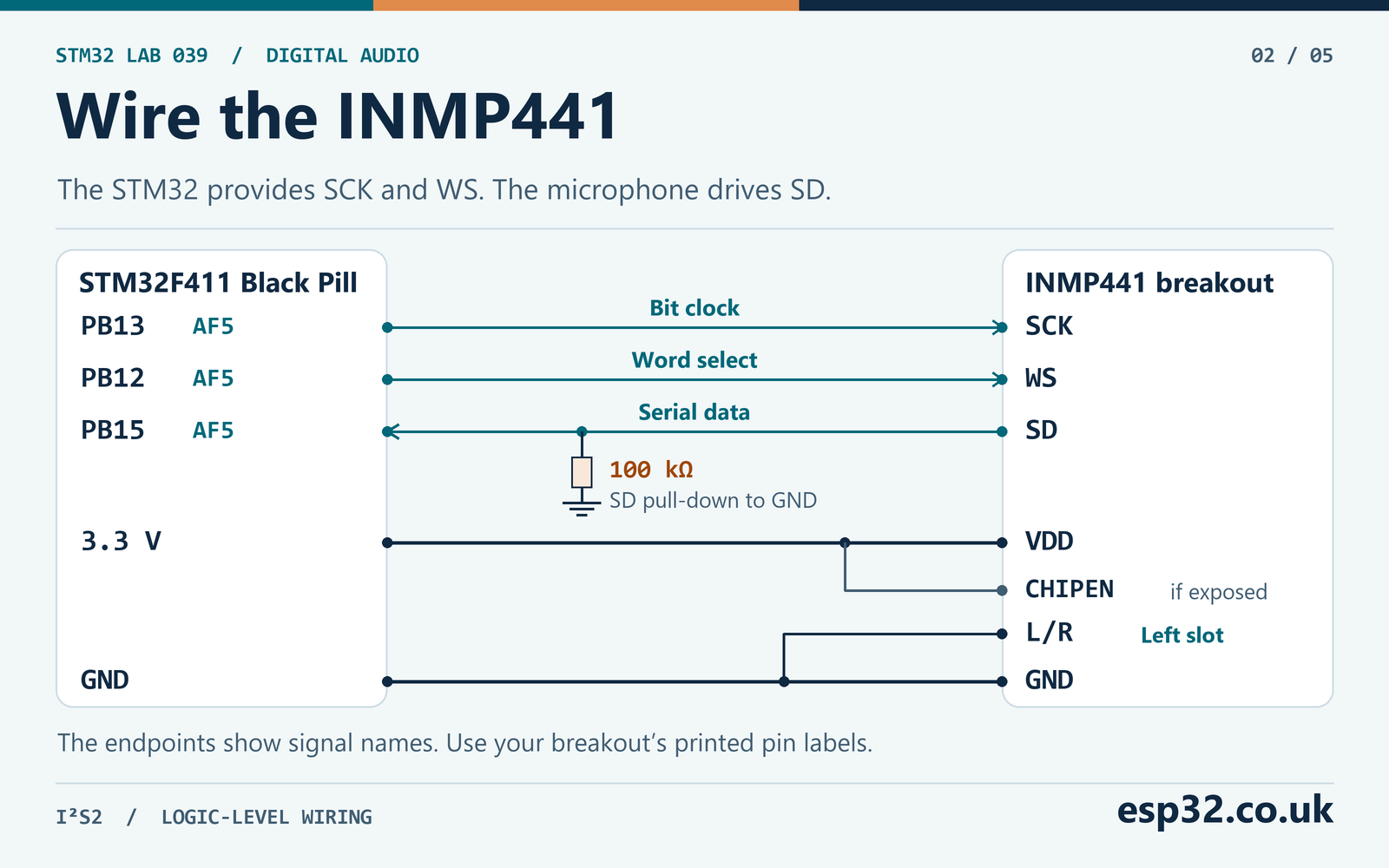
The pull-down gives SD a defined level when the microphone’s output is high impedance. TDK specifies that the part releases SD after the least significant bit, and it leaves the unselected slot available for a second microphone. Check whether your breakout already provides the pull-down and local supply bypassing. For a bare device, follow the datasheet wiring and fit the 100 nF capacitor close to VDD. Tie CHIPEN high if you can access it and the breakout has not already done so. Avoid driving the clock and word-select pins into an unpowered microphone. TDK InvenSense INMP441 datasheet
Keep the bit-clock wire short and give it a nearby ground return. Connect the logic analyser ground to the same return. At the bench, check the clock amplitude and edges with a short probe ground. A heavily loaded clock trace can affect STM32 master receive as well as the microphone’s view of the signal. Measure at the microphone end when diagnosing a long or messy jumper run.
Set the I²S clock to a nominal 16 kHz
This lab keeps the core and APB1 on the nominal 16 MHz internal oscillator with no bus division. The audio clock comes from PLLI2S, sourced from the same HSI oscillator. The F411 audio PLL has its own M field. Set PLLI2SM to 8, PLLI2SN to 128 and PLLI2SR to 5. The resulting oscillator input is 2 MHz, the audio VCO runs at 256 MHz nominal and the I²S kernel clock is 51.2 MHz. The CPU and I²S kernel clocks therefore have different frequencies even though they use the same source.
| Clock or divisor | Calculation | Nominal result |
|---|---|---|
| PLLI2S VCO input | 16 MHz ÷ 8 | 2 MHz |
| PLLI2S VCO output | 2 MHz × 128 | 256 MHz |
| I²S kernel clock | 256 MHz ÷ 5 | 51.2 MHz |
| Effective I²S prescaler | 2 × I2SDIV + ODD | 2 × 25 + 0 = 50 |
| Bit clock | 51.2 MHz ÷ 50 | 1.024 MHz |
| Stereo frame rate | 1.024 MHz ÷ 64 | 16,000 frames/s |
| Frame period | 1 ÷ 16,000 Hz | 62.5 µs |
The I²S divider uses a different relationship when master clock output is enabled. The INMP441 takes SCK and WS, so disable MCLK and use the 64-bit-clock relation above. In the audited F4 HAL, the 24-bit format and disabled MCLK make the initialisation code choose a prescaler based on 64 clocks per sample period. With these inputs, the generated prescaler register should show I2SDIV = 25, ODD = 0 and MCKOE = 0. Read the register after I²S initialisation if the scope result differs from the table. ST RM0383 reference manual · ST HAL I²S source
A divider that gives exactly 16,000 in the calculation still depends on the physical oscillator frequency. If a scope reads 15.92 kHz on WS, the captured samples are arriving at 15,920 per second. The expected bit clock in that case is 1.01888 MHz. A file written with a 16,000 Hz header would play about 0.50% faster than the capture. For a test with a known audio tone, measure WS over many cycles and use the measured rate when interpreting the result. A crystal clock requires a fresh PLL calculation for the oscillator actually fitted to your board.
Keep the PB13 output speed at High in the generated GPIO settings. ST errata ES0287 describes a delayed clock feedback problem that can corrupt the final bit in I²S master reception. For the High or Very High output speed setting, the errata table gives 42 MHz as the maximum APB frequency in I²S mode with its stated 30 pF load. The 16 MHz APB1 used here is below that limit. If you later raise the CPU clock or move to a heavily loaded bus, recheck the APB1 divisor, pin speed and actual edges. The separate slave-mode WS synchronisation erratum becomes relevant if an external device supplies the clocks. ST ES0287 errata
Configure I²S2 and the receive DMA
Create a HAL project for STM32F411CEUx and keep Serial Wire debug enabled. Select HSI as the system and PLL input source and configure the audio PLL separately. Verify the generated clock configuration chooses PLLI2S for I²S and writes the M, N and R values from the table before MX_I2S2_Init(). CubeMX releases differ in how they present the I²S clock tree, so inspect the generated code and the resulting peripheral clock. The expected value from HAL_RCCEx_GetPeriphCLKFreq(RCC_PERIPHCLK_I2S) is 51,200,000 based on the nominal HSI setting. STM32CubeMX and CubeIDE setup
| I²S2 setting | Lab value |
|---|---|
| Mode | Half-duplex Master Receive |
| Standard | Philips I²S |
| Data format | 24-bit data in a 32-bit channel frame |
| Audio frequency | 16 kHz |
| Clock polarity | Low |
| I²S clock source | Internal PLLI2S |
| Master clock output | Disabled |
| Full-duplex extension | Disabled |
In the DMA tab add the SPI2 receive request. The F411 DMA request table labels it SPI2_RX, even when the I²S mode is selected. The main I²S2 receive path uses DMA1 Stream 3, Channel 0. An entry for an I²S extension has a different role. Select peripheral-to-memory direction, disable peripheral address increment and enable memory address increment. Set both alignments to halfword, enable circular mode and leave the FIFO off. High stream priority is adequate for the isolated lab. An NVIC priority of 5 with pre-emption grouping set to use pre-emption bits is a reasonable starting point when SysTick uses a lower priority.
The generated I²S MSP initialisation should enable the GPIOB and SPI2 clocks, configure the three AF5 pins, initialise the DMA handle and link it to hi2s2.hdmarx. Make sure the DMA1 clock is enabled before any DMA stream registers are configured. In a normal CubeMX project, call MX_DMA_Init() before MX_I2S2_Init(). Enable DMA1_Stream3_IRQn, then confirm the interrupt handler calls HAL_DMA_IRQHandler() with the linked RX handle. A DMA stream can move data with its interrupt disabled, so watching NDTR count down does not prove that the callbacks are wired. STM32 DMA concepts and HAL setup
Read the Philips timing on a logic analyser
In Philips I²S, the WS level identifies the channel. Low is left and high is right. WS changes one bit clock before the first significant bit of the next channel. If you configure the receiver or analyser for MSB-justified mode, it expects that bit at the channel boundary and can show a one-bit shift. With the polarity in this lab, decode data on the rising bit-clock edges. Set the analyser to 24 data bits and 32 clocks per slot if it offers both controls.
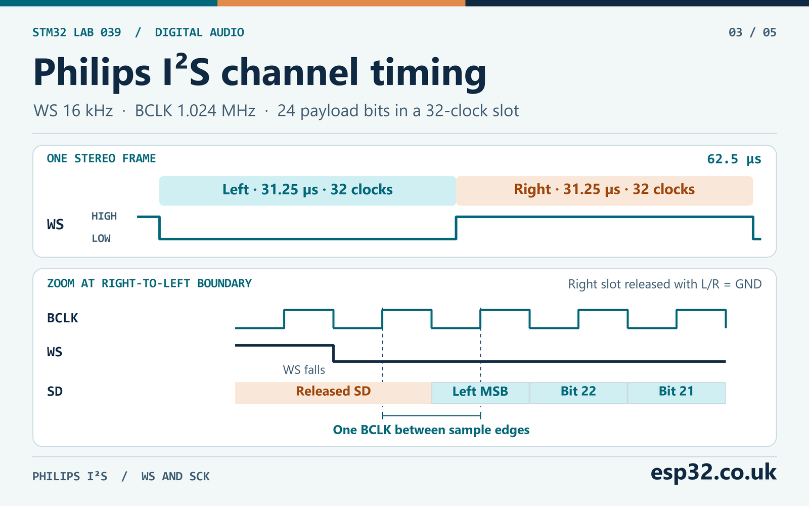
Expect 32 SCK periods between successive WS edges and 64 over one full WS cycle. An individual SCK period is about 977 ns and a WS half-period is 31.25 µs. A cheap analyser can decode the pattern if it samples several times faster than SCK and the input thresholds suit 3.3 V. To see the one-clock lead clearly, capture enough frames to identify a negative sample with a high sign bit and then zoom in on the corresponding WS edge. With one left microphone, the right slot should be mostly low with the pull-down present. A pulled-down high-impedance line may take some time to fall, so a trailing transition on SD is not automatically another data word.
At initial power-up the INMP441 specifies zero output for the first 2¹⁸ SCK cycles. At 1.024 MHz that is 256 ms, so the lab waits 350 ms after starting the clocks before reading any statistics. The wait is measured from the call that starts I²S reception. A delay before starting reception does not give the microphone the required clock cycles. The document also gives separate wake timings for standby and CHIPEN power-down. Treat this lab as a continuous capture from initial power-up and recalculate the delay if you change the bit clock.
Size the buffer in the units HAL expects
The F411 data register provides a 16-bit view of a receive transfer. The reference manual’s 24-bit receive example reads the first two sample bytes as one halfword. The third sample byte arrives in the high eight bits of the next halfword. The low eight bits of that second read do not carry sample data. Pass a uint16_t array to the HAL, let DMA increment by halfwords and keep both transfers that belong to the slot.
The CubeF4 HAL accepts the number of channel words as the Size argument in 24-bit mode. In the v1.8.3 source, HAL_I2S_Receive_DMA() doubles this argument before starting DMA. A channel word is one slot, so a buffer containing 256 stereo frames requires 512 channel words and 1,024 physical DMA halfwords. Pass 512 to HAL. Passing the array length of 1,024 makes this driver request 2,048 halfwords and write past the end of a 1,024-halfword array. A wrong count can overwrite unrelated state even if the analyser shows perfect clocks.
| Quantity | One half | Whole ring |
|---|---|---|
| Stereo frames | 128 | 256 |
| Channel words | 256 | 512 |
| DMA halfwords | 512 | 1,024 |
| SRAM bytes | 1,024 | 2,048 |
| Time span at nominal 16 kHz | 8 ms | 16 ms |
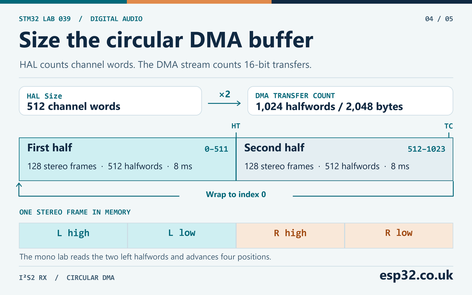
One full stereo frame in the buffer takes four positions in chronological order. Index zero is the left high halfword, index one is the left low halfword, index two is the right high halfword and index three is the right low halfword. The next frame starts at index four. The halfway boundary at index 512 is also a stereo frame boundary. Selecting the right slot changes the offset by two halfwords and leaves the four-halfword stride intact. If you pick a buffer size with the half boundary in the middle of a frame, the same index formula will not work for both callbacks.
The receiver writes 16,000 × 4 × 2 = 128,000 bytes per second into SRAM. The inactive right slot contributes to that number even though the microphone is mono. If you subsequently emit one 16-bit PCM sample per frame, the useful output is 32,000 bytes per second before any transport overhead. These two numbers answer different questions. The first sizes the incoming DMA path and the second sizes a mono recording or a link to another device.
Convert two halfwords into a signed sample
Shift the first halfword left eight positions and shift the second right eight positions. OR the results into a 24-bit unsigned pattern. The sign bit of that pattern is bit 23. The code below flips bit 23 with XOR, converts the resulting nonnegative pattern to int32_t and subtracts 0x800000. This produces a defined signed result for the entire range without a signed left shift or an implementation-defined right shift of a negative number.
| High halfword | Low halfword | Pattern | Signed value |
|---|---|---|---|
0x1234 | 0x56A5 | 0x123456 | 1,193,046 |
0xFEDC | 0xBA00 | 0xFEDCBA | −74,566 |
0x7FFF | 0xFF00 | 0x7FFFFF | 8,388,607 |
0x8000 | 0x00FF | 0x800000 | −8,388,608 |
0xFFFF | 0xFFFF | 0xFFFFFF | −1 |
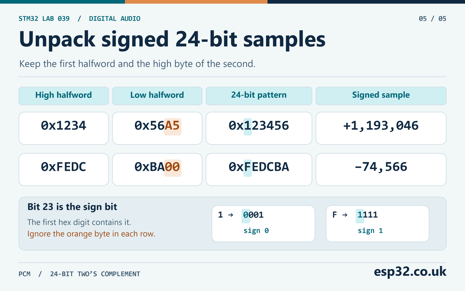
The 0xA5 and 0xFF in the discarded byte of the table are deliberate test inputs. A correct decoder gives the same result for every value in that byte. Casting the buffer to a uint32_t * on the STM32 would instead place the first halfword at the low end of the CPU’s 32-bit load. That is a memory representation choice and does not match the order in which the I²S register receives the bits. The explicit shifts also avoid changing the DMA alignment or requiring the buffer to be aligned for 32-bit loads.
For an easy sanity check, think about the all-ones pattern. Its 24-bit signed value is −1. If the plot shows 16,777,215, the extraction got the bits but treated them as unsigned. If a negative sample appears near a quarter of full scale with obvious discontinuities, verify the decoded bus alignment and compare the exact raw halfwords before assuming a sign bug. Swapped halfwords, Philips timing errors and unsigned conversion can produce different symptoms in the same recording.
Add the capture module to the project
Place mic_lab.h in Core/Inc and mic_lab.c in Core/Src, or in the equivalent application folders for your generated project. Keep HAL callback registration disabled so the driver’s weak callback names are overridden by the definitions below. If your project already defines one of those callbacks, integrate the call in the existing definition and dispatch by handle. Two strong functions of the same name produce a link error.
#ifndef MIC_LAB_H
#define MIC_LAB_H

#include "stm32f4xx_hal.h"

typedef struct {
    int32_t min, max, mean;
    uint32_t blocks, late, hal_error, overrun;
} MicSnapshot;

HAL_StatusTypeDef Mic_Start(I2S_HandleTypeDef *i2s);
MicSnapshot Mic_Read(void);

#endif
#include "mic_lab.h"
enum {
FRAMES_PER_HALF = 128,
HALFWORDS_PER_FRAME = 4,
HALF = FRAMES_PER_HALF * HALFWORDS_PER_FRAME,
RING = 2 * HALF,
SLOT_OFFSET = 0 /* Use 2 with L/R tied high. */
};
static uint16_t ring[RING];
static I2S_HandleTypeDef *receiver;
static volatile MicSnapshot latest;
static int32_t unpack24(uint16_t high, uint16_t low)
{
uint32_t bits = ((uint32_t)high << 8) | ((uint32_t)low >> 8);
return (int32_t)(bits ^ 0x800000U) - 0x800000;
}
HAL_StatusTypeDef Mic_Start(I2S_HandleTypeDef *i2s)
{
if (receiver != NULL) {
return HAL_BUSY;
}
if (i2s == NULL || i2s->Instance != SPI2 || i2s->hdmarx == NULL ||
i2s->Init.Mode != I2S_MODE_MASTER_RX ||
i2s->Init.DataFormat != I2S_DATAFORMAT_24B ||
i2s->hdmarx->Init.Mode != DMA_CIRCULAR ||
i2s->hdmarx->Init.MemDataAlignment != DMA_MDATAALIGN_HALFWORD ||
i2s->hdmarx->Init.PeriphDataAlignment != DMA_PDATAALIGN_HALFWORD ||
__HAL_I2S_GET_FLAG(i2s, I2S_FLAG_RXNE) != RESET ||
(i2s->Instance->I2SCFGR & SPI_I2SCFGR_I2SE) != 0U) {
return HAL_ERROR;
}
receiver = i2s;
__DMB();
HAL_StatusTypeDef result = HAL_I2S_Receive_DMA(i2s, ring, RING / 2U);
if (result != HAL_OK) {
receiver = NULL;
}
return result;
}
static int half_is_idle(uint32_t start, uint32_t remaining)
{
return remaining != 0U && remaining <= RING &&
((remaining <= HALF) == (start == 0U));
}
static void publish_half(I2S_HandleTypeDef *i2s, uint32_t start)
{
if (i2s != receiver || latest.hal_error || latest.overrun) {
return;
}
if (__HAL_I2S_GET_FLAG(i2s, I2S_FLAG_OVR) != RESET) {
latest.overrun = 1U;
return;
}
uint32_t before = __HAL_DMA_GET_COUNTER(i2s->hdmarx);
if (!half_is_idle(start, before)) {
++latest.late;
return;
}
__DMB();
const volatile uint16_t *samples = &ring[start + SLOT_OFFSET];
int32_t min = INT32_MAX, max = INT32_MIN, sum = 0;
for (uint32_t n = 0; n < FRAMES_PER_HALF; ++n) {
uint32_t index = n * HALFWORDS_PER_FRAME;
int32_t value = unpack24(samples[index], samples[index + 1U]);
if (value < min) {
min = value;
}
if (value > max) {
max = value;
}
sum += value;
}
__DMB();
uint32_t after = __HAL_DMA_GET_COUNTER(i2s->hdmarx);
if (__HAL_I2S_GET_FLAG(i2s, I2S_FLAG_OVR) != RESET) {
latest.overrun = 1U;
return;
}
if (after > before || !half_is_idle(start, after)) {
++latest.late;
return;
}
latest.min = min;
latest.max = max;
latest.mean = sum / FRAMES_PER_HALF;
++latest.blocks;
}
void HAL_I2S_RxHalfCpltCallback(I2S_HandleTypeDef *i2s)
{
publish_half(i2s, 0U);
}
void HAL_I2S_RxCpltCallback(I2S_HandleTypeDef *i2s)
{
publish_half(i2s, HALF);
}
void HAL_I2S_ErrorCallback(I2S_HandleTypeDef *i2s)
{
if (i2s == receiver) {
latest.hal_error |= HAL_I2S_GetError(i2s);
}
}
MicSnapshot Mic_Read(void)
{
uint32_t mask = __get_PRIMASK();
__disable_irq();
MicSnapshot copy = latest;
__set_PRIMASK(mask);
return copy;
}Call the module once after the generated peripheral initialisation. Add the include and the watch variable in the corresponding CubeMX user regions. Add the startup call and delay before the main loop and the two loop statements inside it. The generated Error_Handler() should stop so you can inspect the failed setup. In this lab, reset the STM32 before a fresh start or after a latched error.
/* Includes and file scope */
#include "mic_lab.h"
volatile MicSnapshot mic_watch;

/* After MX_DMA_Init() and MX_I2S2_Init() */
if (Mic_Start(&hi2s2) != HAL_OK) {
    Error_Handler();
}
HAL_Delay(350U);

/* Inside the main loop */
mic_watch = Mic_Read();
HAL_Delay(50U);
Flash over SWD, let the board run and inspect mic_watch. Use a live expression where available or halt briefly after the value has updated. A halted CPU can stop servicing DMA interrupts while the peripheral continues. Reset and run again after a long halt before judging the counters. The code takes a short interrupt-protected copy of the seven fields for the foreground. It keeps the live DMA buffer private so the foreground never holds a pointer to samples that DMA could be overwriting.
The half callbacks do bounded work. Each reads 128 samples, tracks the extrema and accumulates an integer sum. In the worst case of 128 full negative-scale samples the sum is −1,073,741,824, still within a signed 32-bit accumulator. The positive bound is 1,073,741,696. The mean is an integer division with truncation towards zero. For a quick level indication, calculate peak to peak as max - min. Its maximum possible value is 16,777,215, also within the signed 32-bit range. Keep floating-point processing, file writes and blocking I/O out of the callbacks.
Know when DMA owns each half
Once the half-transfer interrupt fires, the first half has been filled and DMA is moving through the second. Once the transfer-complete interrupt fires and the circular count reloads, DMA starts filling the first half again and the second can be read. That gives the callback roughly 8 ms after each boundary, less whatever time the interrupt spent waiting. A flag in the foreground does not extend the deadline. It only records that a boundary passed.
The code reads NDTR before and after processing. For the first half it accepts a remaining count from 1 through 512. For the second it accepts 513 through 1,024, after the reload. A transient zero is treated conservatively and the block is dropped. The second check rejects a half that became active while it was being read. The memory barriers bracket the sample reads, and the volatile access forces the compiler to read the DMA-written buffer. Neither operation locks a DMA stream. The schedule still has to leave the CPU enough time to service the interrupt.
The late count records callbacks the guard rejected. It cannot reconstruct a full revolution of the ring if interrupts stay masked long enough for the hardware flags to coalesce. No count increase is a substitute for a timing measurement. If you extend the callback, toggle a spare GPIO at entry and exit and compare the longest pulse and the timing of its start with the buffer boundaries. Run this check while the other parts of your application are active.
There are three useful health fields. blocks increments when a snapshot is published, late counts rejected half callbacks, and hal_error accumulates errors reported through the HAL error callback. The separate overrun field latches if the code sees the I²S OVR flag during a half callback. In the selected HAL, DMA errors can reach the error callback, while the ordinary receive-DMA start does not enable the SPI2 error interrupt. That is why the module explicitly checks OVR. If the callbacks stop altogether, inspect the hardware status and stream flags as well as the snapshot. The monitor stops publishing on a latched overrun or HAL error because a missing halfword can shift the slot interpretation.
On a healthy run, blocks advances approximately 125 times a second. The debugger watch is refreshed once per 50 ms, so its count normally increases by six or seven between refreshes. This is a latest-value monitor and the intervening summaries are intentionally replaced. The count advances much faster than the watch and is separate from the missed-deadline count. Read the snapshot through Mic_Read() when using it in the main loop so the fields belong to the same publication.
Prove the capture at the bench
First look at the two clock pins with the module running. A frequency counter on PB13 should read near 1.024 MHz. PB12 should read near 16 kHz and alternate on 32-clock intervals. If both clock frequencies are wrong by the same ratio, work backward from the bit clock to the I²S prescaler and then to the PLL source. If the ratio between the two clocks is wrong, check the frame format and peripheral mode before tuning the oscillator.
Next check the stream count. It should sweep down from 1,024 and reload while the receiver runs. Observe it live or through firmware instrumentation. Reading it once at a breakpoint can hide the sweep because the counter reaches whatever state the live peripheral allows while the core is stopped. Verify that the DMA interrupt hits both half and full callbacks. Remove breakpoints in those callbacks before looking for clean data.
After the startup wait, compare the watch values with the room quiet and with a steady sound. A small speaker playing a continuous tone or a repeated clap is enough to check that the spread increases. Room noise, module orientation and distance change the observed values. The peak-to-peak reading is a relative electrical level in sample counts. Converting it to sound pressure level would require a calibrated stimulus, a known gain path and a defined measurement window.
If both clocks and callbacks look right but the sound has no effect, temporarily configure the code for the other channel offset and compare. A breakout with L/R strapped high sends the right slot, while the default code reads the left. The scope or analyser should show which slot carries changing bits. Resolve that selection first. Changing the shift count to make numbers appear in a plot can conceal a wiring error.
| Observation | Check first |
|---|---|
| Neither clock toggles | Return from Mic_Start(), PLLI2S ready flag, AF5 pins and master receive mode |
| SCK toggles but WS frequency is unexpected | The 24-bit format, 32-bit slots and disabled master clock |
| Clocks work but SD stays flat | Module VDD, common ground, CHIPEN, selected slot and the 350 ms delay |
| SD changes but NDTR is fixed | SPI2_RX request, DMA1 Stream 3 Channel 0, clock and RXDMAEN |
| NDTR moves but statistics never update | Stream IRQ enable, NVIC priority and the handler’s HAL DMA call |
| Values are unsigned, clipped or alternate unexpectedly | Two-halfword assembly, signed conversion and left/right stride |
late grows when other work runs | Long interrupt masking, callback workload or competing higher-priority IRQs |
hal_error or overrun becomes nonzero | Inspect DMA and I²S flags, fix the cause and reset before retrying |
The protocol decoder and the watch variables check different parts of the path. A good waveform proves the microphone is driving the wire. A good waveform with bad raw words points at receiver configuration, transfer size or signal integrity. Good raw halfwords with bad signed values point at the conversion. If you suspect sporadic low-bit corruption, use a short connection, review the SCK speed and APB1 errata limits, and compare a known serial pattern from a suitable test source with the corresponding raw words.
Turn the monitor into an audio stream
The diagnostic module reports statistics because they fit in a single small snapshot. For audio recording, preserve every sample block in order. Copy converted samples out of the completed DMA half before its deadline into a separate buffer pool. A queue can hand those completed buffers to the file or transport task. Give each block a sequence number and track queue overflows. If the producer runs out of free buffers, record the drop or stop the capture according to your application’s policy. Never hand the consumer a pointer directly into the rotating DMA ring.
For signed PCM16, one defined conversion takes the upper 16 bits of the 24-bit sample pattern, then sign-extends that 16-bit pattern or writes its two bytes directly. For example, the upper 16 bits of 0xFEDCBA are 0xFEDC. In a little-endian PCM16 file, that sample is stored as bytes DC FE. Its signed value is −292. Taking the upper bits maps the two ends of the 24-bit range to −32,768 and +32,767. Dividing a negative integer by 256 in C truncates towards zero and can give a different result from discarding the low eight bits. Pick one conversion and keep it consistent across the device and reference tool.
At 16 kHz, mono PCM16 needs 32,000 bytes/s and one minute of raw sample data uses 1,920,000 bytes. A standard 8N1 UART carries ten line bits per byte, so continuous PCM16 alone would require at least 320,000 baud. A typical 115,200-baud debug connection has room for only about 11,520 bytes/s before packet overhead. It can carry the occasional level summary or short extracts. Continuous audio needs a faster transport or local storage and a queue sized for the consumer’s worst pauses. STM32 UART, interrupts and DMA · STM32 microSD and FatFs data logging
For a file writer, emit the sample rate, channel count and sample size that match the recorded PCM. The PCM16 sample rate is the WS frequency. The fact that the I²S bus carried two slots does not make a one-microphone file stereo. A stereo file with only the mono payload would consume pairs of consecutive samples as left and right, shortening playback and shifting the pitch. Also record the measured sample rate when you compare captures across boards or oscillators.
Common I²S microphone questions
Can two INMP441 microphones share the data line?
TDK shows two devices on a single SD trace with common SCK and WS and opposite L/R selections. Each drives only its own slot and releases the line at the end of its sample. Use a shared pull-down and local bypassing at both devices. Two microphones with the same L/R selection could drive the line at the same time. The 64 clocks per stereo frame and the DMA ring dimensions stay the same when both slots are populated. To capture both channels, decode both pairs in each four-halfword frame and preserve their order when you write the stream.
Can I choose 16-bit I²S and save DMA bandwidth?
This microphone still expects 32 clocks per slot, and this lab uses the 24-bit format so you can observe the whole sample and discard bits later. The F411 has a separate 16-bit extended mode that uses a 32-bit slot with a different receive register and DMA transfer count. A plain 16-bit slot would reduce the number of clocks per frame and violate the microphone requirement. If you try 16-bit extended mode, verify the exact alignment in RM0383 and redo the buffer sizing and conversion. The supplied module deliberately checks for the 24-bit format.
Why does the code keep capturing when the room is silent?
I²S has no separate data-ready pin that tells the STM32 to wait for speech. As long as the clocks run, every stereo frame produces the same receive transfer pattern. During silence the sample values change while the clock and DMA cadence continue. To implement a trigger, keep capturing into a bounded buffer, compute a level over a chosen window and have the application start saving when the threshold is crossed. Include a short pre-trigger buffer if you need the beginning of the event.