A CAN controller can accept a frame into a transmit mailbox even when the bus is disconnected. It can also acknowledge a frame that its receive filter discards. Those two details explain many first-day CAN problems. A message that says “sent” might only mean that software queued a request, while an empty receive FIFO might reflect a filter decision on a bus that works perfectly well.
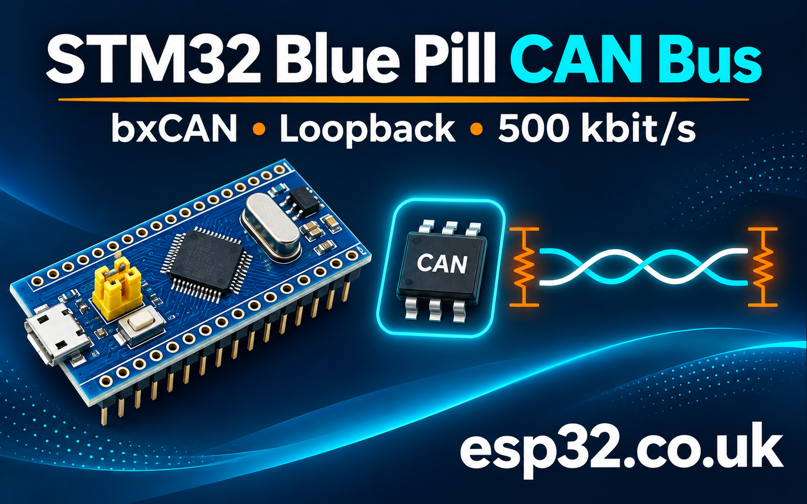
In this esp32PriceAliExpress price.co.uk/ guide, you will build two tests on the STM32F103C8T6PriceAliExpress price Blue PillPriceAliExpress price. First, use bxCAN silent loopback to check frame creation, filter configuration and FIFO reads with one board. Then put two boards in Normal mode, add one 3.3 V CAN transceiver at each end, and prove that a frame crosses a terminated 500 kbit/s bench bus. The same Cube HAL code gives you a sequence number on the receive side and error register snapshots when something goes wrong.
The lab uses Classical CAN, one standard identifier and four data bytes. The circuit is an isolated low-voltage bench setup. Its test frames have no assigned meaning outside the two boards, and a vehicle or production machine can interpret the same identifier as a real command. Keep this test bus separate from equipment in service.
What bxCAN does and where the transceiver fits
The STM32F103 contains the CAN protocol controller. It builds frames, arbitrates for the bus, checks received frames and applies filters before placing accepted frames into its receive FIFOs. The chip’s CAN_TX and CAN_RX signals are single-ended logic. An external transceiver converts those signals to and from the differential CANH and CANL pair. The transceiver has no application-level knowledge of which identifier you want to receive. ST STM32F103x8/xB datasheet
Both nodes observe the bus as they transmit or receive. When several nodes begin transmitting at once, the arbitration field resolves which frame continues. With otherwise comparable standard data frames, a smaller numeric identifier wins because the corresponding dominant bit overrides a recessive bit at the first point of difference. The losing controller can stop sending without corrupting the winner’s frame. Treat the identifier as a description of a message and its arbitration priority. If an application needs addressing, define how that works above the CAN frame.
The receiver signals an acknowledgement in the ACK slot when it receives a valid frame in an active mode. Application filtering happens independently of that acknowledgement. This means a sender can observe successful transmission while the receiver’s program sees nothing in FIFO0. It also means that a passive listener can decode what it hears while providing no ACK. This distinction matters if you replace Node B with a USB CAN adapter that is set to listen-only mode.
| Item | Choice in this lab | What to verify |
|---|---|---|
| Protocol | Classical CAN | The F103 bxCAN hardware supports standard and extended identifiers and up to eight data bytes |
| Identifier | Standard 11-bit 0x321 | Both ends agree on the identifier format and frame type |
| Payload | Four bytes | Marker, sequence, marker, sequence complement |
| Test mode | Silent loopback first | Own frame arrives in FIFO0 with the transceivers disconnected |
| Bus mode | Normal on both boards | A second active node can acknowledge and receive the frame |
The SPI and I²C articles in the series move data between devices with a shared clock. CAN has no separate clock wire. Every node needs a compatible nominal bit rate and must resynchronise to transitions on the bus. Getting a clean-looking electrical waveform is one part of bringing up CAN. Getting the receiver’s sampling and the protocol parameters right is another. STM32 SPI tutorial · STM32 I²C tutorial
Choose a Blue Pill pin mapping
The default bxCAN mapping uses PA11 for CAN_RX and PA12 for CAN_TX. These are also the USB D− and D+ pins on this device. This lab uses the PB8/PB9 remap, with PB8 receiving and PB9 transmitting. That keeps the transceiver connections away from the Blue Pill’s USB data circuitry. The STM32F103 also shares dedicated memory between its USB device and CAN peripherals, so leave the MCU USB peripheral disabled even when CAN is remapped. A separate USB-UART adapter can still provide the serial console. ST RM0008, AFIO remapping and bxCAN
Check the labels on the actual board and the generated pin view. CubeMX may describe the device’s single CAN controller as CAN or CAN1. Select the pin pair explicitly. On the F1, remapping is an AFIO register setting, so choosing PB8/PB9 as ordinary GPIO inputs and outputs is insufficient. Inspect the generated MSP code for AFIO clock enable, the CAN remap selection, and alternate-function push-pull on PB9. PB8 must be the CAN input. Also confirm that nothing else in the project uses PB8/PB9, such as remapped I²C1. Blue Pill pinout guide
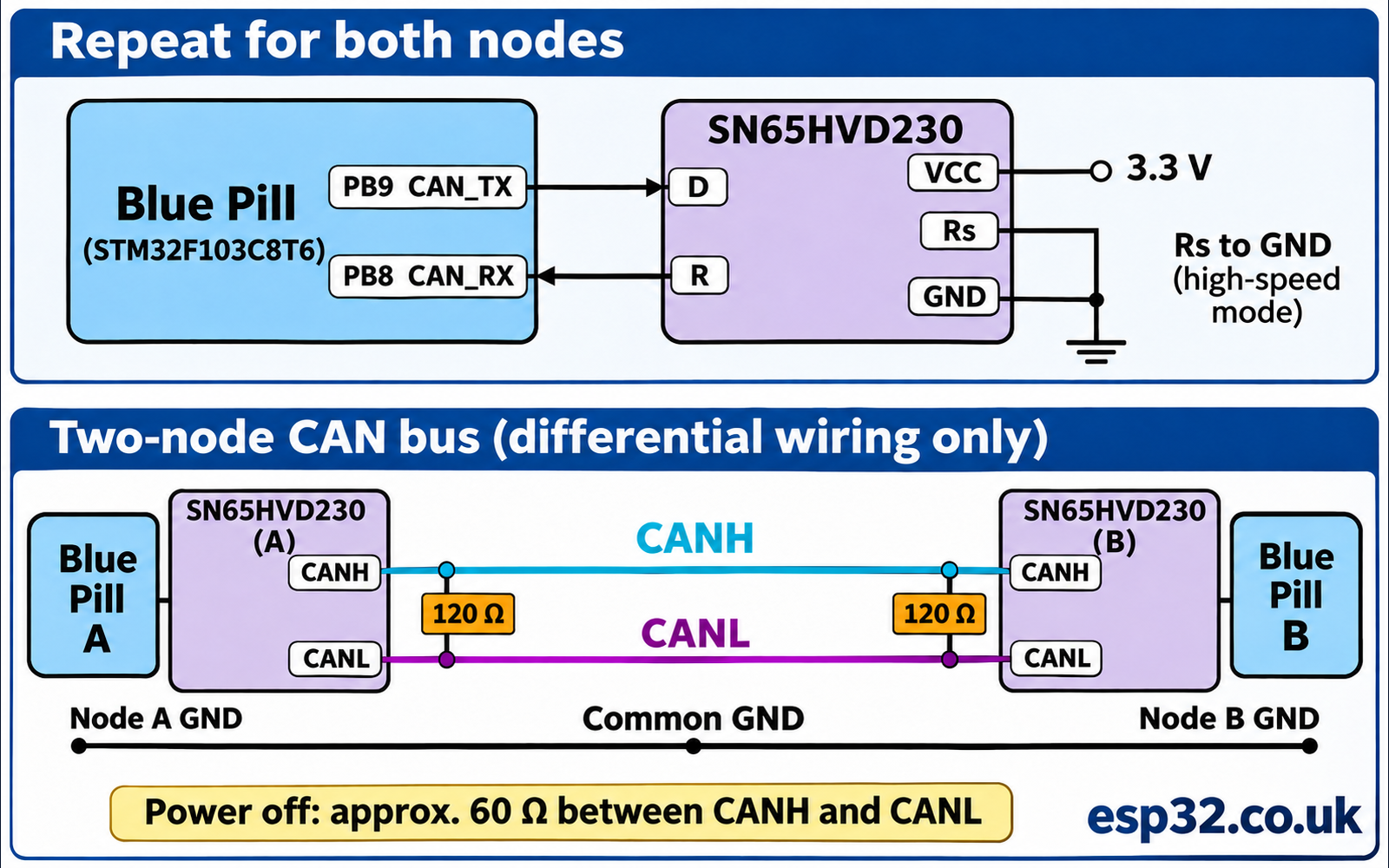
You can perform the first test without the external transceiver. For the second test, use two STM32F103 boards and two transceiver boards built around the TI SN65HVD230 or an equivalent verified design. The following connections apply to the SN65HVD230 itself. Breakout boards sometimes label its D and R pins TXD and RXD, or use labels that describe the host connection instead of the transceiver pin. Follow the module schematic when the silkscreen is ambiguous. TI SN65HVD23x datasheet
| Blue Pill or supply | SN65HVD230 | Purpose |
|---|---|---|
| PB9 CAN_TX | D, pin 1 | Controller sends logic into the transceiver |
| PB8 CAN_RX | R, pin 4 | Transceiver returns logic to the controller |
| Regulated 3.3 V | VCC, pin 3 | Transceiver supply |
| Common GND | GND, pin 2 | Logic and bus reference in the bench setup |
| GND, if exposed and supported by the module | Rs, pin 8 | Selects high-speed operation on the SN65HVD230 |
| Bus CANH | CANH, pin 7 | High side of the differential pair |
| Bus CANL | CANL, pin 6 | Low side of the differential pair |
The transceiver is a 3.3 V part. A different module may need a different supply, have a separate I/O voltage pin, or use a differently named standby pin. Check the actual part marking and schematic before reusing the table. For a bare SN65HVD230, provide local supply decoupling and follow TI’s application circuit. The Vref output is unnecessary for the simple termination used here. Leave it unused in this circuit. Grounding Rs selects high-speed operation on this part. A module that fixes Rs internally can require different handling. TI SN65HVD23x datasheet, pin functions and application information
Terminate a two-node bench bus
Start with a short twisted pair, with CANH running to CANH and CANL to CANL. Carry a ground reference between the two nodes in this bench setup, especially if they are powered separately. Fit one 120 Ω resistor across CANH and CANL at each physical end of the pair. If each module already includes a 120 Ω resistor, those two resistors can be the termination. Extra resistors on a third tap would load the pair and lower the measured resistance. Avoid long stubs and star wiring for the first test.
With both nodes unpowered and all other equipment disconnected, measure across CANH and CANL. Two 120 Ω resistors in parallel give about 60 Ω. A reading near 120 Ω often means only one termination is fitted. About 40 Ω suggests three 120 Ω resistors. These are clues to inspect the circuit, since real modules can add other resistance paths. A multimeter test checks the static load. It cannot show how the bus behaves during a fast edge. TI SN65HVD23x datasheet, typical application and termination
Termination belongs across the differential pair, never from each line to a supply rail in this simple circuit. If the module documentation is unclear, measure each unpowered module across its CAN terminals before assembling the link. That gives you a way to account for a soldered resistor that you did not intend to add. In a longer network, the end positions are set by the cable route. A module that has the first identifier or sends the most traffic can sit anywhere along that route. A schematic that shows two terminators is incomplete if it leaves their physical positions ambiguous.
Bring the bench system up one connection at a time. Verify the supply and the UART prompt on each Blue Pill first. Then power down, make the controller-to-transceiver connections, and connect the pair and ground reference. Use the meter check before powering both nodes. This sequence gives you intermediate observations you can repeat when changing a board or cable. If the new wiring introduces an unexpected supply drop, stop and identify the connection responsible before trying more transmit commands.
Use one known power source per board and make sure its regulator can supply the transceiver as well as the MCU. A separate serial adapter needs signal ground and 3.3 V UART logic. Leave its supply lead disconnected if the Blue Pill already has power. During bring-up, measure the transceiver’s VCC at its own pins while the board transmits. A rail that looks correct on a meter at idle can still dip during an active burst. Follow the USART1 setup guide for the PA9 TX and PA10 RX console connections.
Calculate 500 kbit/s from the APB1 clock
bxCAN gets its peripheral clock from APB1. For this example, use a verified 8 MHz HSE crystal, PLL ×9, 72 MHz SYSCLK and APB1 divided by two, giving 36 MHz PCLK1. In CubeMX select a crystal oscillator for a board with a crystal, rather than bypass mode, which expects an external clock signal. If the crystal value differs, build a clock tree with the correct value and recalculate the timing. The code checks the clock frequency reported by HAL, which relies on the project’s oscillator configuration and nominal frequency. It does not measure the actual crystal.
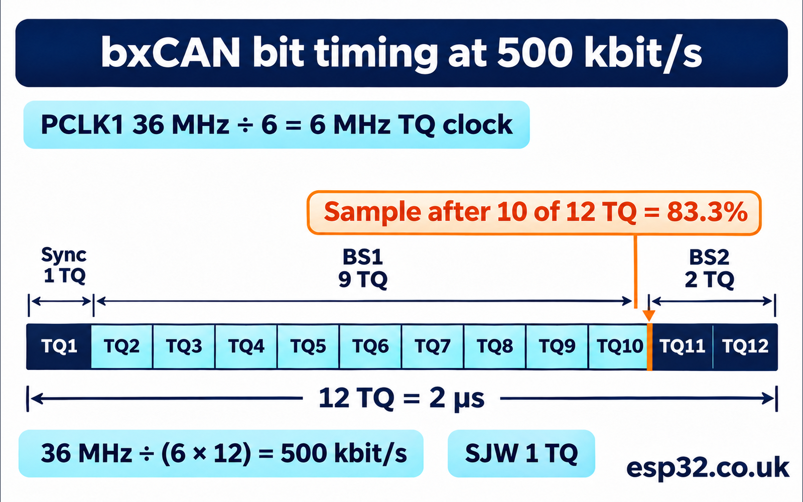
The bit is split into a one-quantum synchronisation segment, BS1 and BS2. The sample occurs between BS1 and BS2. With a prescaler of six, each quantum takes six cycles of the 36 MHz CAN clock, about 166.7 ns. The lab uses nine quanta for BS1 and two for BS2, so the whole bit takes 12 quanta or 2 µs. The sample point is 10/12 of the bit, about 83.3%. Use a resynchronisation jump width of one quantum for this example.
| Setting | Lab value | Consequence |
|---|---|---|
| APB1 clock | 36 MHz | Input to bxCAN prescaler |
| Prescaler | 6 | 6 MHz time-quantum clock |
| Sync segment | 1 TQ | Fixed part of the nominal bit |
| BS1 | 9 TQ | Sample after 1 + 9 quanta |
| BS2 | 2 TQ | Two quanta after the sample |
| SJW | 1 TQ | Bounds resynchronisation adjustment |
| Nominal bit rate | 36 MHz ÷ 6 ÷ 12 | 500 kbit/s |
Use the HAL segment constants CAN_BS1_9TQ, CAN_BS2_2TQ and CAN_SJW_1TQ. The raw BTR fields encode their counts minus one. That encoding does not mean you should enter eight and one as segment lengths in a GUI that asks for the actual quanta. If APB1 is 18 MHz with these same settings, the rate becomes 250 kbit/s. APB timer clock doubling does not apply to bxCAN, so use PCLK1 directly in the calculation. ST RM0008, bxCAN bit timing and CAN_BTR
The sample point is one property of a timing configuration. Oscillator tolerance and the propagation delay through the cable and transceivers also matter. A short bench link removes much of the cable delay from the problem. If the same configuration is moved to a long harness, retest it under realistic conditions instead of assuming that a nominal bit rate and a matching decimal sample point prove the whole design. The first success criterion here is a stable exchange between two nearby nodes with known hardware.
Set up the two firmware builds in CubeMX
Select STM32F103C8Tx, Serial Wire debugging and USART1 asynchronous with 115200 baud, eight data bits, no parity and one stop bit. Use CAN on the PB8/PB9 alternate mapping, set the timing above and leave the MCU USB function disabled. Follow the CubeMX setup guide if you need a reminder of the generated project structure and code regions.
For the first build, select combined Silent Loopback. This sends the frame through the controller’s internal receive path while leaving the external TX output recessive in the combined mode. The internal test ignores the need for a remote acknowledgement. Keep the transceiver disconnected. After checking that build, set the mode to Normal, regenerate, and build for both bench nodes. In the generated initialisation, compare hcan.Init.Mode with CAN_MODE_SILENT_LOOPBACK or CAN_MODE_NORMAL before flashing. ST RM0008, bxCAN test modes
Set Auto Retransmission to Disabled for this deliberate one-shot test. A failed attempt is easier to associate with a single t command when the controller does not keep retrying by itself. Leave time-triggered mode, automatic wake-up and automatic bus-off recovery disabled for the initial exercise. FIFO0 is polled, so leave CAN interrupts off in this version. Document the receive FIFO overrun policy if you later change the FIFO lock setting. The example’s sparse test messages are intended to stay well below the three-frame FIFO capacity. ST STM32CubeF1 HAL CAN driver
The code assumes the generated CAN handle is named hcan. If yours is named hcan1, adjust the reference in the main.c snippets. Keep the project’s HAL CAN module enabled and use its current HAL_CAN_Start, HAL_CAN_AddTxMessage and HAL_CAN_GetRxMessage APIs. Some older examples use a different transmit structure and obsolete HAL functions. Compare examples against the headers that came with your project before copying their initialization patterns.
| Generated field or setting | Value to check |
|---|---|
hcan.Init.Prescaler | 6 |
hcan.Init.SyncJumpWidth | CAN_SJW_1TQ |
hcan.Init.TimeSeg1 | CAN_BS1_9TQ |
hcan.Init.TimeSeg2 | CAN_BS2_2TQ |
hcan.Init.Mode | Silent Loopback for the first build, Normal for both physical nodes |
hcan.Init.AutoRetransmission | DISABLE for one attempt per command |
Save the .ioc file and mark the two firmware builds clearly. It is easy to reflash one node and accidentally leave the other in loopback. The boot banner exposes the raw mode value so you can check both terminals after a flash. Make sure the generated CAN initialisation call runs before can_console_start(). Also make sure that the UART banner is printed only after the USART has been configured. These order checks help if a lab that worked once starts failing after regeneration.
Pack a filter for one standard data frame
In a bxCAN 32-bit filter, the standard identifier sits in bits 31:21. For 0x321, that places 0x6420 in the high halfword. Set the high mask to 0xFFE0 to compare all eleven standard identifier bits. In the low halfword, compare IDE at bit 2 and RTR at bit 1 with a mask of 0x0006. Both expected bits are zero, selecting a standard data frame. The other bits in the filter word do not participate in this match. ST RM0008, bxCAN identifier filtering
The mask bit answers whether a position must match. The filter value answers what that position must contain. With a zero mask, the identifier value is irrelevant. That can be useful for a short diagnostic when you want to determine whether frames reach the controller at all, but it should be a deliberate temporary change. If you set only the standard ID mask without comparing IDE and RTR, other frame types can slip through a filter that looks exact in a quick review. For a useful negative test, send 0x322 as a separate test build on Node A while keeping Node B’s filter at 0x321.
Configure bank zero in mask mode, 32-bit scale, with the result assigned to FIFO0. This device has one CAN controller, so SlaveStartFilterBank does not split the filters with a second instance. The application checks the resulting frame again, including its length and the marker bytes, before printing the sequence. That extra check catches an invalid payload even when the identifier filter worked exactly as intended.
To see the match in hex, combine the halves as 0x64200000 for the filter value and 0xFFE00006 for the mask. A standard data frame with ID 0x321 produces the expected identifier bits. ID 0x320 differs in one of the compared bits, while an extended frame with the same eleven leading bits differs at IDE. A remote frame differs at RTR. This gives you three independent negative checks. If a later application accepts a family of IDs, write down the range and calculate the mask from the bits they share. Test the first rejected value on each side of the intended range, since a mask defines a pattern rather than an arbitrary numeric interval.

Add the test frame and serial console code
The package includes the same two source files and main.c snippets shown below. Put the header and C file in the generated project’s include and source directories. The frame layout is four bytes in order. Byte zero is 0xA5, byte one is the sequence, byte two is 0x5A, and byte three is the bitwise complement of the sequence. The complement is a convenient test pattern for the lab. The CAN controller’s CRC still handles frame-level integrity, and a real application must define how it handles missing, repeated and late messages.
/* file: can_lab.h */
#ifndef CAN_LAB_H
#define CAN_LAB_H

#include "stm32f1xx_hal.h"

#define CAN_LAB_ID 0x321u
#define CAN_LAB_DLC 4u

typedef enum {
    CAN_LAB_RX_EMPTY,
    CAN_LAB_RX_VALID,
    CAN_LAB_RX_UNEXPECTED,
    CAN_LAB_RX_ERROR
} CanLabRxResult;

HAL_StatusTypeDef CanLab_Start(CAN_HandleTypeDef *can);
HAL_StatusTypeDef CanLab_Queue(CAN_HandleTypeDef *can, uint8_t sequence,
                               uint32_t *mailbox);
CanLabRxResult CanLab_Read(CAN_HandleTypeDef *can, uint8_t *sequence);

#endif
/* file: can_lab.c */
#include "can_lab.h"
HAL_StatusTypeDef CanLab_Start(CAN_HandleTypeDef *can)
{
CAN_FilterTypeDef filter = {0};
filter.FilterBank = 0u;
filter.FilterMode = CAN_FILTERMODE_IDMASK;
filter.FilterScale = CAN_FILTERSCALE_32BIT;
filter.FilterIdHigh = CAN_LAB_ID << 5u;
filter.FilterIdLow = 0u;
filter.FilterMaskIdHigh = 0x7FFu << 5u;
filter.FilterMaskIdLow = (1u << 2u) | (1u << 1u);
filter.FilterFIFOAssignment = CAN_FILTER_FIFO0;
filter.FilterActivation = CAN_FILTER_ENABLE;
HAL_StatusTypeDef status = HAL_CAN_ConfigFilter(can, &filter);
return status == HAL_OK ? HAL_CAN_Start(can) : status;
}
HAL_StatusTypeDef CanLab_Queue(CAN_HandleTypeDef *can, uint8_t sequence,
uint32_t *mailbox)
{
if (HAL_CAN_GetTxMailboxesFreeLevel(can) == 0u) return HAL_BUSY;
CAN_TxHeaderTypeDef header = {0};
header.StdId = CAN_LAB_ID;
header.IDE = CAN_ID_STD;
header.RTR = CAN_RTR_DATA;
header.DLC = CAN_LAB_DLC;
header.TransmitGlobalTime = DISABLE;
uint8_t data[8] = {0xA5u, sequence, 0x5Au, (uint8_t)(sequence ^ 0xFFu)};
return HAL_CAN_AddTxMessage(can, &header, data, mailbox);
}
CanLabRxResult CanLab_Read(CAN_HandleTypeDef *can, uint8_t *sequence)
{
if (HAL_CAN_GetRxFifoFillLevel(can, CAN_RX_FIFO0) == 0u) {
return CAN_LAB_RX_EMPTY;
}
CAN_RxHeaderTypeDef header = {0};
uint8_t data[8] = {0};
if (HAL_CAN_GetRxMessage(can, CAN_RX_FIFO0, &header, data) != HAL_OK) {
return CAN_LAB_RX_ERROR;
}
if (header.IDE != CAN_ID_STD || header.RTR != CAN_RTR_DATA ||
header.StdId != CAN_LAB_ID || header.DLC != CAN_LAB_DLC ||
data[0] != 0xA5u || data[2] != 0x5Au ||
(uint8_t)(data[1] ^ 0xFFu) != data[3]) {
return CAN_LAB_RX_UNEXPECTED;
}
*sequence = data[1];
return CAN_LAB_RX_VALID;
}Use a single foreground owner for both the mailbox and receive functions. With that arrangement, the software check for a free mailbox is a way to report busy without introducing a second producer. The HAL call still has its own return value. The send buffer is eight bytes long even though the logical payload is four, because the F1 HAL implementation accesses all eight data positions when loading mailbox registers. The receive buffer is also eight bytes. ST STM32CubeF1 HAL CAN implementation
/* USER CODE BEGIN Includes */
#include "can_lab.h"
#include <stdio.h>
#include <string.h>
/* USER CODE END Includes */

/* USER CODE BEGIN 0 */
static uint8_t next_sequence;

static void can_print(const char *text)
{
    (void)HAL_UART_Transmit(&huart1, (const uint8_t *)text,
                           (uint16_t)strlen(text), 100u);
}

static void can_console_start(void)
{
    char line[104];
    (void)snprintf(line, sizeof line, "CAN mode=0x%08lX PCLK1=%lu Hz\r\n",
                   (unsigned long)hcan.Init.Mode,
                   (unsigned long)HAL_RCC_GetPCLK1Freq());
    can_print(line);
    if (HAL_RCC_GetPCLK1Freq() != 36000000u) {
        can_print("Expected 36 MHz PCLK1. Check CAN timing.\r\n");
        Error_Handler();
        return;
    }
    if (CanLab_Start(&hcan) != HAL_OK) {
        can_print("CAN filter or start failed.\r\n");
        Error_Handler();
        return;
    }
    can_print("t=queue test frame, e=read CAN status\r\n");
}

static void can_console_poll(void)
{
    char line[104];
    uint8_t command = 0;
    if (HAL_UART_Receive(&huart1, &command, 1u, 2u) == HAL_OK) {
        if (command == 't') {
            uint32_t mailbox = 0;
            HAL_StatusTypeDef status = CanLab_Queue(&hcan, next_sequence, &mailbox);
            if (status == HAL_OK) {
                (void)snprintf(line, sizeof line, "Queued seq=%u mailbox mask=0x%lX\r\n",
                               (unsigned)next_sequence, (unsigned long)mailbox);
                ++next_sequence;
                can_print(line);
            } else {
                can_print(status == HAL_BUSY ? "No free mailbox\r\n" : "Queue failed\r\n");
            }
        } else if (command == 'e') {
            uint32_t esr = hcan.Instance->ESR;
            uint32_t tsr = hcan.Instance->TSR;
            (void)snprintf(line, sizeof line,
                           "ESR=0x%08lX TEC=%lu REC=%lu LEC=%lu TSR=0x%08lX\r\n",
                           (unsigned long)esr, (unsigned long)((esr >> 16u) & 0xFFu),
                           (unsigned long)((esr >> 24u) & 0xFFu),
                           (unsigned long)((esr >> 4u) & 7u), (unsigned long)tsr);
            can_print(line);
        }
    }

    for (unsigned i = 0; i < 3u; ++i) {
        uint8_t sequence = 0;
        CanLabRxResult result = CanLab_Read(&hcan, &sequence);
        if (result == CAN_LAB_RX_EMPTY) break;
        if (result == CAN_LAB_RX_ERROR) {
            can_print("FIFO read failed\r\n");
            break;
        }
        if (result == CAN_LAB_RX_UNEXPECTED) {
            can_print("Unexpected CAN header or payload\r\n");
            continue;
        }
        (void)snprintf(line, sizeof line, "RX ID=0x321 DLC=4 seq=%u\r\n",
                       (unsigned)sequence);
        can_print(line);
    }
}
/* USER CODE END 0 */

/* In USER CODE BEGIN 2, after CAN and USART initialisation: */
/* can_console_start(); */

/* In the generated while (1) body: */
/* can_console_poll(); */
The example reports a queued sequence before it has evidence of receipt. In Silent Loopback, your single board provides that evidence when its local FIFO receives the test frame. In Normal mode, the terminal on the second board provides it. The sequence counts queue requests and wraps after 255. A gap can be evidence of a missing message if only one sender is active and the receiver saw all preceding records. Across a reset or multiple senders, sequence values need additional context.
Run the internal loopback first
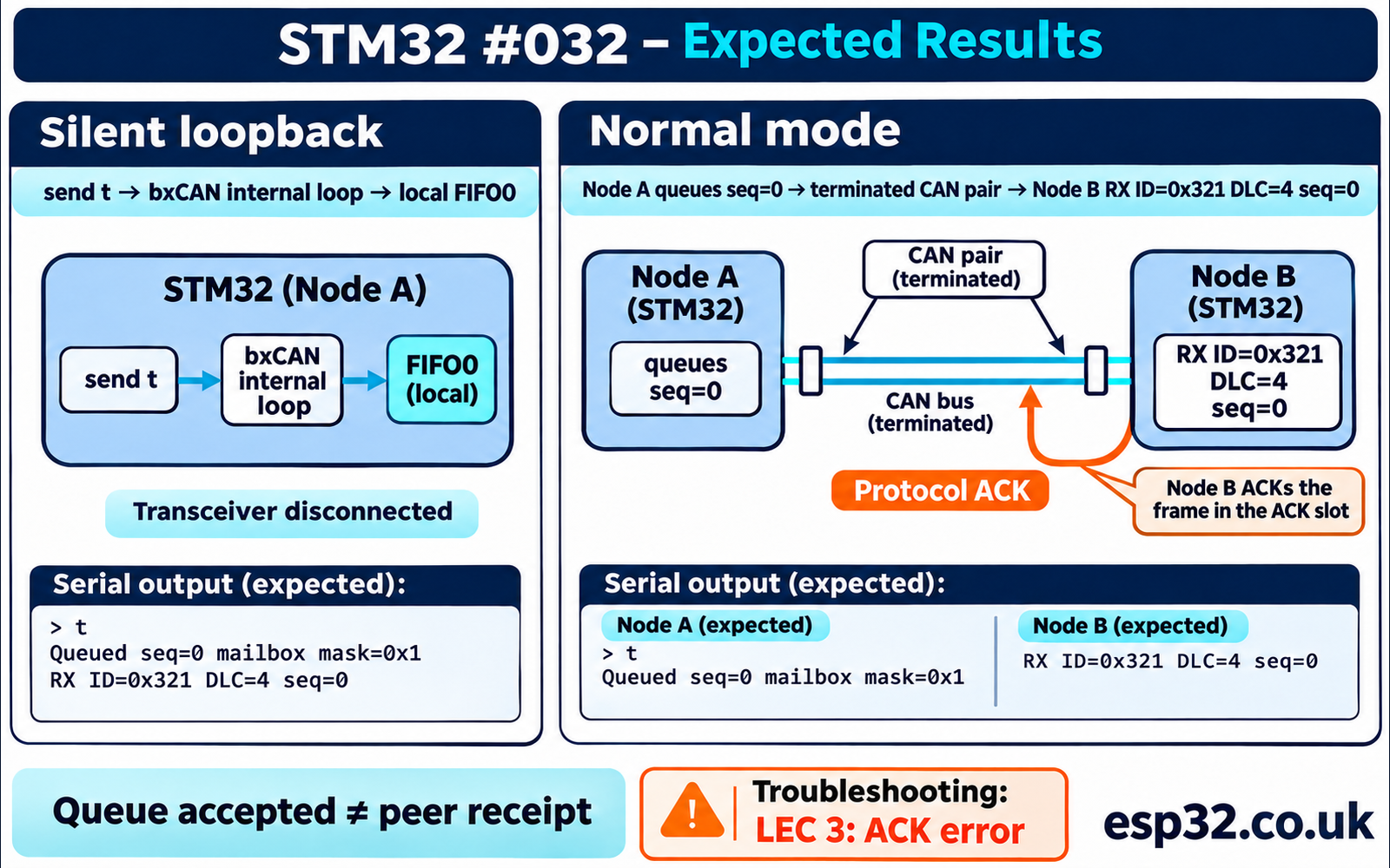
With the Silent Loopback build on one Blue Pill, leave the CAN transceiver and pair disconnected. Open the serial terminal and check that PCLK1 is reported as 36 MHz. Press t once. The first queue message should report seq=0. The same terminal should then show RX ID=0x321 DLC=4 seq=0. Try again and confirm that the sequence advances. If the console prints the queue message without a receive line, inspect the selected mode, the filter activation and which FIFO you are reading.
Loopback checks the path from software through the controller and back to software. Its transmit and receive timing come from the same local timebase, and it can pass even if the actual oscillator is wrong. There is no second transceiver to exercise and no external node to acknowledge. That is why the next test uses two independent clocks, the physical differential pair and an active receiver.
For a practical checkpoint, record the build’s mode, PCLK1, first two sent sequences and first two received sequences. Keep that record with your generated project. If a later build fails on the bench, you can reflash the loopback version to separate a software regression from an external problem. The best comparison uses the same filter and payload code in both builds, with only the hardware operating mode changed. If the firmware is already part of a larger application, temporarily disable other traffic producers so their activity does not obscure these few test frames.
To check the payload path more closely, set a breakpoint after the receive function fills the buffer and inspect the bytes. Sequence zero should produce A5 00 5A FF. Sequence one should produce A5 01 5A FE. Compare the header separately from the payload. The 0x321 identifier is in the header, so it will not appear as a data byte. Resume the programme before you try sending additional frames.
Run Normal mode on two boards
Build both nodes in Normal mode, connect the transceivers and terminators with the boards unpowered, then power up and open both terminals. Check that the reported mode is zero and PCLK1 is 36 MHz on each. Send t from Node A alone. Node A should report the queued frame and Node B should report the matching ID and sequence. Node A should not see its own frame in its receive FIFO in Normal mode. Do several one-at-a-time sends and check that the numbers agree across the two terminals.
Now stop the sender and try the filter negative test. Give Node A a different identifier for one build while keeping Node B’s filter fixed at 0x321. In a working setup, Node B can acknowledge the valid alternate-ID frame at the protocol level while discarding it from FIFO0. Use a CAN analyser, the ACK slot on a suitable trace or the sender’s transmit status to investigate that result. Restore the original test identifier afterwards. Avoid having two nodes send different payloads under the same identifier at the same instant. They can reach the data field without resolving arbitration and then disagree on the bits.
For a controlled missing-ACK trial, leave the termination connected and put the receiver in Silent mode or hold it out of Normal operation in a way that preserves the wiring and passive termination. With only the one active sender, one frame request can produce an ACK error. Restore the peer to Normal and repeat. An already active third node may acknowledge the frame and invalidate this comparison. Keep the test on the two-node bench circuit and account for any analyser that can transmit an ACK.
Use error registers to narrow the fault
Press e on the sending board after a failed test. The ESR snapshot gives the transmit error counter, receive error counter and last error code. In RM0008, LEC value 3 indicates an acknowledgement error. LEC is a snapshot that can change as the controller sees subsequent bus activity. An ACK error suggests that the sender transmitted without seeing a valid acknowledgement. Check for an absent, silent or mismatched peer. Check bus wiring and timing too, since a receiver that cannot decode the frame will also fail to acknowledge it. ST RM0008, CAN_ESR and CAN_TSR
The transmit status register has a completion and outcome group for each mailbox. Use the mailbox mask from the queue line to select the group. For mailbox zero, RQCP0 indicates completion of the request and TXOK0 indicates a successful transmission for that completion. Completion alone covers failure and abort as well. Take the snapshot before queuing another frame into that mailbox, since the flags can change with reuse. This program does not install a CAN IRQ handler that would consume completion flags in the background. A design that uses notifications should log the result at its callback or event handler instead.
Try to capture one example of each distinct failure while the bench circuit is easy to restore. With the receiver in Normal mode but filtering a different ID, record the sender outcome and the empty receive console. With the receiver in Silent mode, record the ACK error snapshot. With the receiver at half the intended bit rate, expect decoding problems and record whatever the registers actually report, rather than treating a particular LEC as guaranteed. Restore the matching settings between trials and confirm a good frame each time. That gives you a reference for later diagnosis when you cannot reproduce the original setup exactly.
| What you observe | What it tells you | First check |
|---|---|---|
| Loopback RX works, but Normal mode has no waveform | The software path can work without the external link | PB8/PB9 remap, PB9 logic, transceiver power and Rs |
| TX request completes with ACK error | No valid acknowledgement was observed | Active peer, common bit rate and bus connections |
| Sender TXOK, receiver FIFO remains empty | Another active node acknowledged the frame | Receiver filter, IDE, RTR and FIFO assignment |
| Messages appear only at a lower rate | Timing or physical margin may be limited | Both bit timing settings, termination, stubs and reference ground |
| FIFO overrun during a burst | The application is draining FIFO too slowly | Remove per-frame terminal prints and review the consumer rate |
An error counter rising with every attempt is a reason to stop the repeated sends and examine the bench setup. bxCAN can move to error passive and, for appropriate transmit fault conditions, bus-off. A node in bus-off cannot keep participating in normal traffic. A string of missing acknowledgements alone does not guarantee that a lone transmitter will eventually reach bus-off, because error confinement rules apply. Record the status and correct the cause. If you later enable automatic recovery, decide how your application will report the fault and when it is safe to resume traffic.
Check the signal and workload before scaling up
If you have a logic analyser, start with PB9 and PB8 against the board ground. At idle, the transceiver interface should show the recessive logic state. A transmit burst on PB9 with no corresponding activity on the pair points toward the transceiver, its supply or its mode. A differential scope measurement across CANH and CANL can help show ringing or an unexpectedly small differential swing. Use a suitable differential probe or a measurement method that respects the scope’s ground connections. A grounded probe clip on one bus wire can short that wire to earth in a bench setup.
When measuring a known bit, the nominal duration at 500 kbit/s is 2 µs. An analyser’s error decode can also help you distinguish a timing mismatch from a frame that the controller accepted but software discarded. Avoid estimating bit rate from an arbitrary wide pulse, since adjacent equal bits and the stuffing rule affect observed transition spacing. Capture several frames and compare the decoded identifier and data to the console records. Record the analyser’s mode if it can operate as an active node.
One four-byte frame consumes more bus time than its 32 payload bits. A standard Classical CAN data frame with four bytes has 76 bits from start of frame through end of frame before stuffing, or 79 including the three-bit intermission. At 500 kbit/s the 79-bit lower bound is 158 µs. At a hundred such messages per second, those nominal bits use about 1.58% of the link. Actual bus occupancy can be higher because of bit stuffing, retries and other frames. The calculation is a way to size the initial workload, and a trace can reveal how far the actual traffic deviates from it.
The UART console has a separate throughput limit. At 115200 baud and 8N1, a 30-character message takes about 2.6 ms on the wire. A few CAN frames can arrive during that print even at a bus load that feels modest. For a busy version of the application, put received frames into a bounded queue or update counters from the receive path, and print a summary at a slower interval. Keep separate counters for FIFO overrun, application queue overflow and payload rejection. They represent different places where data can disappear, and lumping them together makes a working physical bus look unreliable.
Once the basic exchange is stable, make Node A send at a defined interval and count gaps on Node B without printing each frame. Confirm that the observed count changes when you deliberately send a different ID. Then introduce a second identifier and give each message a clear meaning, expected interval and loss policy. If the final system sleeps between reports, consider the MCU wake path and transceiver standby behaviour separately. Recheck the CAN peripheral clock after any Stop-mode clock transition. STM32 low-power tutorial