Quick answer: On an STM32F103C8PriceAliExpress price Blue PillPriceAliExpress price, configure a general-purpose timer such as TIM2 with the correct input clock, prescaler (PSC) and auto-reload register (ARR). For a typical 72 MHz timer clock, PSC = 7199 and ARR = 9999 produce one update event per second. Enable the TIM2 interrupt in STM32CubeMX and start it with HAL_TIM_Base_Start_IT(&htim2). To measure incoming edges, configure TIM2 channel 1 on PA0 as input capture and read successive CCR1 timestamps. To create a known test waveform, use TIM3 channel 1 on PA6 as PWM output. All signal connections in this guide are 3.3 V logic, not 5 V power outputs.
In this esp32PriceAliExpress price.co.uk/ guide, we build an accurate mental model of STM32 timers before using three practical configurations: a periodic interrupt, a hardware PWM test waveform, and capture-based frequency measurement. We cover the frequently misunderstood APB prescaler multiplier, 16-bit counter wraparound, timer update versus capture interrupts, exact HAL callback placement, and sensible validation steps. The examples target the STM32F103C8T6 with STM32CubeMX and STM32CubeIDE; other STM32 generations may have 32-bit timers or different clock trees. We do not claim to have physically measured these circuits.
Why hardware timers matter more than another HAL_Delay loop
A microcontroller timer is a counter driven by a selected clock. Once configured, its counting and compare logic operate independently of ordinary application code. A timer can generate a periodic update event, set or clear an output pin at a programmed compare value, capture the instant an external edge arrived, count encoder pulses, or trigger an ADC. Software handles configuration and results, not every individual timing transition.
HAL_Delay(1000) is useful for a first LED exercise but ties program flow to a wait. A hardware timer can interrupt at one-second intervals while the foreground handles serial communication, sensors or a user interface. For fast repetitive signals, hardware PWM remains stable even if the CPU spends time elsewhere. Input capture stores an edge timestamp in hardware, avoiding the uncertain latency of reading a GPIO in a software loop.
That does not mean timers are immune to mistakes. The timer has its own clock domain, the prescaler and auto-reload values are zero-based, and the callback executes only when the update interrupt and NVIC routing are configured. In input-capture work, correct polarity, timer resolution and counter overflow handling become equally important.
What the STM32F103C8 provides
The familiar STM32F103C8T6 is a 72 MHz Cortex-M3 microcontroller with 64 KB specified flash and 20 KB SRAM. Its medium-density timer set includes advanced-control TIM1 and general-purpose TIM2, TIM3 and TIM4. The TIM1 advanced-control unit can provide complementary outputs and dead-time features needed by some motor-control circuits; this tutorial deliberately uses the simpler general-purpose units. The familiar F103C8 implementations of TIM1–TIM4 have 16-bit counters: do not transfer claims about 32-bit TIM2 on later STM32 families to this part.
| Peripheral | Type on F103C8 | Typical role here | Default pins relevant to this guide |
|---|---|---|---|
| TIM1 | Advanced-control, APB2 | Motor-oriented PWM, advanced features | PA8 TIM1_CH1, PA9 CH2, PA10 CH3, PA11 CH4 |
| TIM2 | General-purpose, APB1 | Periodic update and edge timestamp | PA0 TIM2_CH1, PA1 CH2, PA2 CH3, PA3 CH4 |
| TIM3 | General-purpose, APB1 | PWM output / capture | PA6 TIM3_CH1, PA7 CH2, PB0 CH3, PB1 CH4 |
| TIM4 | General-purpose, APB1 | Additional PWM or capture | PB6 TIM4_CH1, PB7 CH2, PB8 CH3, PB9 CH4 |
| SysTick | Cortex-M3 system timer | HAL time base by default | Internal: no external signal pin |
Pin names in this table are MCU alternate functions, not physical pin numbers on every Blue Pill clone. The example does not enable timer remapping. In a design already using I²C1 on PB6/PB7, TIM4 outputs on the same pins would conflict. Similarly, PA6 is also SPI1 MISO: you must choose the function you need. Consult ST’s RM0008 reference manual and the actual board silk screen before connecting anything.
The timer clock: APB1 at 36 MHz can mean TIM2 at 72 MHz
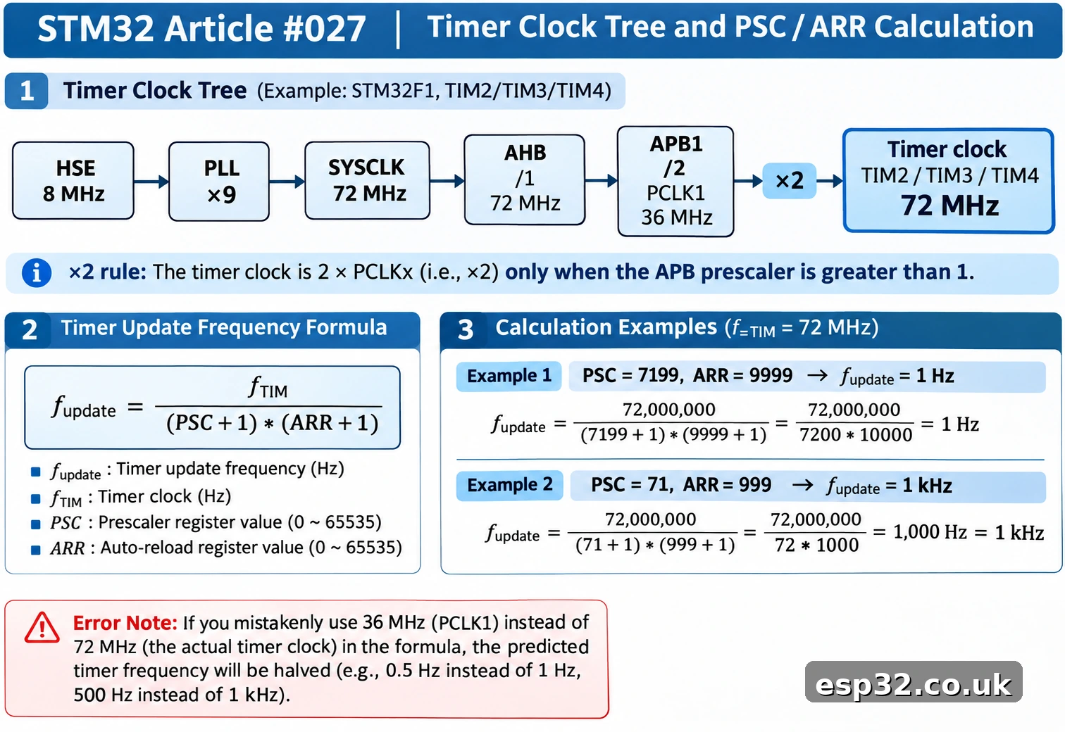
One of the most expensive timer mistakes is entering the APB bus frequency into the timer calculation without checking the timer multiplier. The clock path typically begins with HSE or HSI, goes through PLL and system clock dividers, then through the AHB and APB prescalers. TIM2, TIM3 and TIM4 sit on APB1. TIM1 sits on APB2.
For the classic F103 timer clocking rule, when an APB prescaler is 1, the corresponding timer clock equals the APB peripheral clock. When the APB prescaler is greater than 1, the timer clock is twice the APB peripheral clock. This rule applies to TIM1 on APB2 and the general-purpose TIM2–TIM4 on APB1; do not generalise without checking the reference manual for a different STM32 family.
A common 8 MHz HSE Blue Pill example uses PLL ×9 for SYSCLK = 72 MHz, AHB prescaler ÷1, APB1 prescaler ÷2 and APB2 prescaler ÷1. It produces PCLK1 = 36 MHz and PCLK2 = 72 MHz. Therefore TIM2/TIM3/TIM4 run from 72 MHz, and TIM1 runs from 72 MHz. If the clock tree differs, the numbers in the rest of this tutorial must be recalculated.
| Clock item | Example configuration | Result |
|---|---|---|
| HSE oscillator | 8 MHz external crystal | 8 MHz |
| PLL | ×9 | SYSCLK = 72 MHz |
| AHB prescaler | ÷1 | HCLK = 72 MHz |
| APB1 prescaler | ÷2 | PCLK1 = 36 MHz |
| TIM2/TIM3/TIM4 clock | PCLK1 ×2 | 72 MHz |
| APB2 prescaler | ÷1 | PCLK2 = 72 MHz |
| TIM1 clock | PCLK2 | 72 MHz |
A Blue Pill has no intrinsic guarantee that its external crystal, PLL settings or clone hardware are correct. Check the CubeMX Clock Configuration diagram, the generated SystemClock_Config() function, and when diagnosing unexpected timings, HAL_RCC_GetPCLK1Freq() together with the APB1 prescaler value. Note that the PCLK query returns the peripheral bus clock, not necessarily the timer’s multiplied clock.
Prescaler and ARR calculations without off-by-one errors
For a timer counting upwards from zero, its prescaler divides the input clock by PSC + 1. The counter then advances by one on each timer tick and overflows after ARR + 1 counter ticks. If the repetition counter is not being used, the update-event frequency is:
Timer update frequency: f_update = f_TIM / ((PSC + 1) × (ARR + 1)).
The timer tick frequency is f_tick = f_TIM / (PSC + 1) and its period is T_tick = 1/f_tick. The maximum useful value of a 16-bit ARR is 65535, which corresponds to 65536 counter positions; a prescaler register of 65535 divides by 65536. PSC and ARR are stored register values, not the literal divide factor or number of counts.
For a one-second update event at 72 MHz, choose a 10 kHz counter tick by dividing by 7200. This gives PSC = 7199. Then count 10,000 ticks: ARR = 9999. Calculation: 72,000,000 / (7200 × 10,000) = 1 Hz. For 10 ms, retain PSC 7199 and choose ARR = 99: 10,000 / 100 = 100 Hz or one event every 10 ms. For a microsecond-scale capture clock, use PSC = 71 and ARR = 65535, giving a 1 MHz counter, one microsecond per count and wrap every 65.536 ms.
| Purpose | TIM clock | PSC | ARR | Counter tick | Update frequency / wrap |
|---|---|---|---|---|---|
| One-second update | 72 MHz | 7199 | 9999 | 10 kHz | 1 Hz |
| 10 ms scheduler tick | 72 MHz | 7199 | 99 | 10 kHz | 100 Hz |
| 1 kHz PWM base | 72 MHz | 71 | 999 | 1 MHz | 1 kHz |
| Microsecond capture | 72 MHz | 71 | 65535 | 1 MHz | Wrap at 65.536 ms |
| One-minute interval | 72 MHz | 7199 | 59999 | 10 kHz | 1/60 Hz |
These configurations are illustrative; all depend on the assumed 72 MHz timer clock and count-up operation. In centre-aligned counting modes, update timing and PWM frequency need different treatment. In PWM mode, auto-reload typically controls the period while a capture/compare register (CCR) controls the active portion. The distinction is covered later.
What changes when the clock is only 8 MHz?
A fresh system may still be running from HSI at 8 MHz. With no PLL and default APB prescalers, the timer clock could be 8 MHz rather than 72 MHz. Reusing PSC 7199 and ARR 9999 would yield an update rate of about 0.111 Hz: roughly one event every nine seconds. That is a common reason for a seemingly broken timer. Rather than changing values randomly, inspect the actual clock tree and compute the expected period again. It is also possible that the target pauses the timer while halted under a debugger, depending on debug-freeze settings.
First project: configure TIM2 as a one-second periodic interrupt
For a clean reproduction, create a new STM32F103C8Tx project in STM32CubeMX or use the matching MCU in a supported STM32CubeIDE-integrated flow. Keep SYS → Debug = Serial Wire to preserve PA13 SWDIO and PA14 SWCLK for ST-LINK. Configure a verified 72 MHz clock tree: HSE 8 MHz, PLL ×9, APB1 ÷2 and APB2 ÷1. If your board uses a different oscillator, change the clock plan rather than pretending that 8 MHz HSE is universal.
Open TIM2, select Internal Clock as the source, and choose Counter Mode = Up, Prescaler = 7199 and Counter Period (ARR) = 9999. Use Clock Division = No Division and Auto-Reload Preload = Disabled for a simple first project. In the NVIC settings, enable the TIM2 global interrupt. Generate the project for STM32CubeIDE. Check that MX_TIM2_Init() is called after HAL_Init() and SystemClock_Config(), and that generated code enables the TIM2 peripheral clock in its MSP setup.
No external timer pin is required for this test. The timer update event is internal, and the debug pin mapping is independent. To make the result visible, we count seconds in an interrupt and toggle the onboard Blue Pill LED through the foreground. The usual PC13 LED is active-low, so an output low often lights it. Its drive is limited compared with ordinary GPIOs: do not attach an external high-current load to PC13.
CubeMX settings checklist
| Setting | Value for the TIM2 update test |
|---|---|
| MCU | STM32F103C8Tx |
| System debug | Serial Wire (PA13, PA14 reserved) |
| SYSCLK example | 72 MHz |
| APB1 | 36 MHz, timer clock 72 MHz |
| TIM2 clock source | Internal clock |
| Prescaler | 7199 |
| Counter period | 9999 |
| Counter mode | Up |
| TIM2 NVIC | Enabled |
| PC13 GPIO | Output push-pull, low speed, initial HIGH if active-low LED fitted |
The generated TIM2 code should resemble the following timer initialization. Do not paste a second MX_TIM2_Init() into the project; CubeMX already generates it. This condensed excerpt exists to let you verify settings in the actual output.
static void MX_TIM2_Init(void)
{
    TIM_ClockConfigTypeDef clockSource = {0};
    htim2.Instance = TIM2;
    htim2.Init.Prescaler = 7199;
    htim2.Init.CounterMode = TIM_COUNTERMODE_UP;
    htim2.Init.Period = 9999;
    htim2.Init.ClockDivision = TIM_CLOCKDIVISION_DIV1;
    htim2.Init.AutoReloadPreload = TIM_AUTORELOAD_PRELOAD_DISABLE;
    if (HAL_TIM_Base_Init(&htim2) != HAL_OK) Error_Handler();
    clockSource.ClockSource = TIM_CLOCKSOURCE_INTERNAL;
    if (HAL_TIM_ConfigClockSource(&htim2, &clockSource) != HAL_OK)
        Error_Handler();
}
The essential application change is to start the timer after initialization and respond to the appropriate callback. Add the following to the existing main.c USER CODE sections, rather than replacing the entire generated file. The volatile variable is updated in interrupt context and consumed by the foreground. For a simple single-writer 32-bit count on this 32-bit MCU, the load/store is naturally atomic; for larger structures or multiple writers, use proper synchronization.
/* USER CODE BEGIN PV */
static volatile uint32_t seconds_elapsed = 0;
/* USER CODE END PV */

/* USER CODE BEGIN 2 */
HAL_GPIO_WritePin(GPIOC, GPIO_PIN_13, GPIO_PIN_SET);  // LED OFF
if (HAL_TIM_Base_Start_IT(&htim2) != HAL_OK) Error_Handler();
/* USER CODE END 2 */

/* USER CODE BEGIN 4 */
void HAL_TIM_PeriodElapsedCallback(TIM_HandleTypeDef *htim)
{
    if (htim->Instance == TIM2) {
        seconds_elapsed++;
    }
}
/* USER CODE END 4 */

/* Place in the generated while (1), inside USER CODE BEGIN 3 */
static uint32_t last_shown = 0;
uint32_t now = seconds_elapsed;
if (now != last_shown) {
    last_shown = now;
    HAL_GPIO_TogglePin(GPIOC, GPIO_PIN_13);
}
Keep the foreground sample inside the generated while (1); if your toolchain does not permit a static declaration at that insertion point, declare last_shown at function scope above the loop. The static declaration means it is initialized once, not on every iteration. The callback does almost no work, avoiding long interrupt latency or blocking serial writes. One update per second means one LED state change per second; because the LED alternates on and off, the complete on–off blink cycle is two seconds (0.5 Hz). It is intentional that the LED toggle can skip intermediate changes if the main loop is blocked for several seconds: for a display of elapsed time, track the count rather than assume every update is handled immediately.
Do not forget the IRQ handler
CubeMX normally generates a TIM2_IRQHandler in stm32f1xx_it.c when TIM2 global interrupt is enabled. It should dispatch to HAL with HAL_TIM_IRQHandler(&htim2). A functioning generated project also needs the timer interrupt enabled in NVIC and the TIM2 peripheral clock configured in MSP initialization. Simply defining HAL_TIM_PeriodElapsedCallback() without the IRQ plumbing will never make it execute.
/* Normally generated in stm32f1xx_it.c */
void TIM2_IRQHandler(void)
{
    HAL_TIM_IRQHandler(&htim2);
}
Use the ST-LINK debugger to put a breakpoint in the callback or inspect seconds_elapsed. A breakpoint can distort wall-clock timing because execution stops; remove breakpoints before timing measurements. If the timer is running, a logic analyser on an optional output pin or a serial timestamp is a better way to verify period and jitter than counting by eye.
Build a known 1 kHz waveform using TIM3 PWM
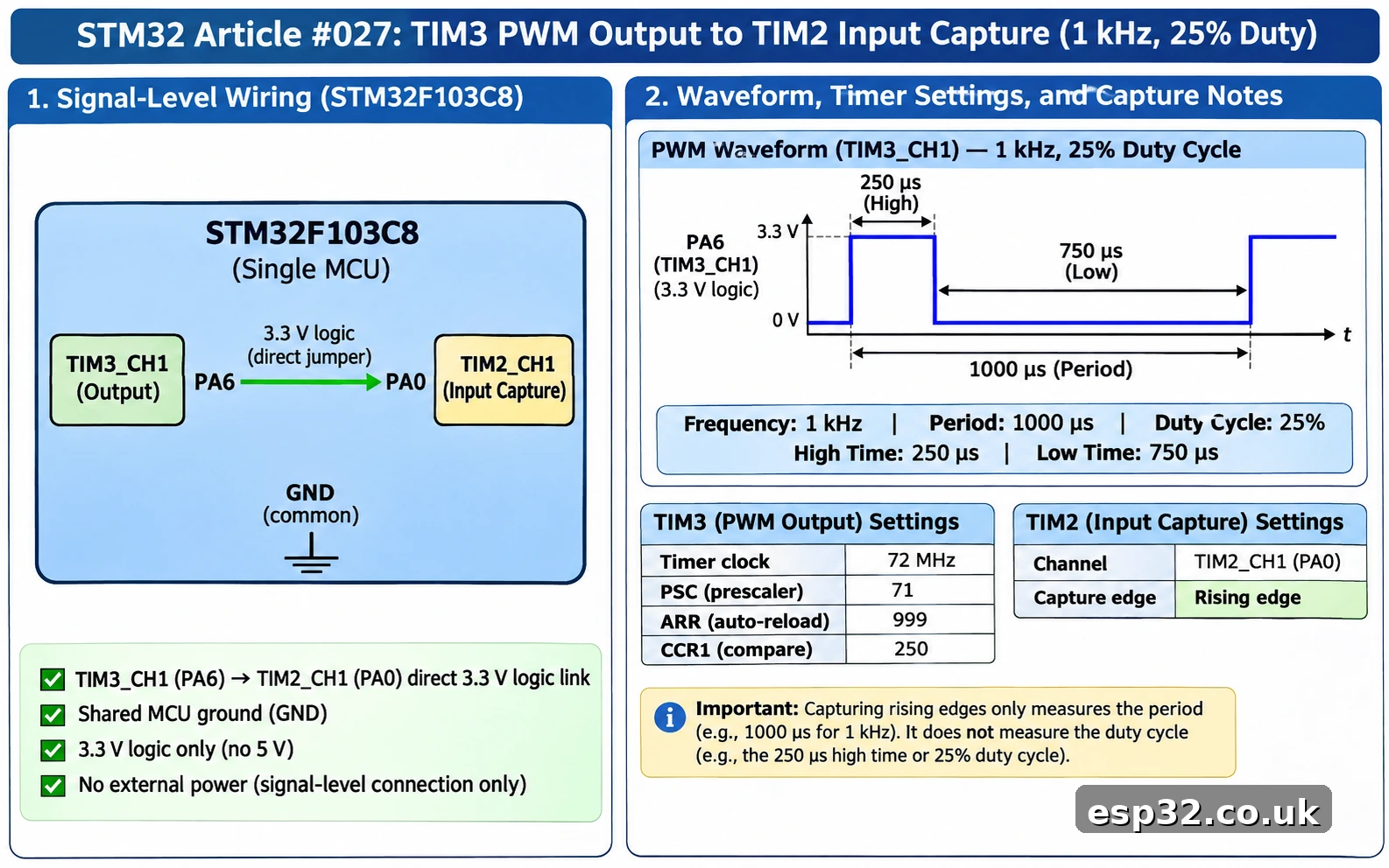
Input capture needs edges to measure. The simplest repeatable test source is another hardware timer inside the same Blue Pill. Configure TIM3 channel 1 on PA6 as PWM output; use TIM2 channel 1 on PA0 as a capture input. A short jumper from PA6 to PA0 can then carry the test waveform. These are two different timer peripherals, so their counters and interrupt modes can be configured independently. Both pins are 3.3 V digital signals, and both share the board’s ground automatically. Do not attach the jumper to 5 V, a motor supply or an RS-232 level shifter.
For PWM, the timer still counts according to the PSC and ARR values. In edge-aligned PWM mode 1 with active-high polarity, a compare value in CCR1 determines the amount of time the channel is active. In the ordinary 0–ARR count-up case, the ideal duty ratio is CCR1 / (ARR+1) for valid compare settings. With PSC = 71, the counter ticks at 1 MHz; with ARR = 999, the PWM repetition rate is 1,000,000 / 1000 = 1,000 Hz. Set CCR1 = 250 to obtain approximately 25% duty cycle, a 250 µs high interval followed by a 750 µs low interval.
| TIM3 parameter | Value | Meaning |
|---|---|---|
| Counter clock | 72 MHz | From APB1 timer multiplier in this example |
| PSC | 71 | Divide by 72: 1 MHz counter |
| ARR | 999 | 1000 counter ticks / PWM period |
| CH1 output pin | PA6 | Default TIM3_CH1, no remap |
| CH1 mode | PWM Generation CH1, PWM mode 1 | Edge-aligned output |
| Pulse / CCR1 | 250 | 25% ideal high time |
| Output polarity | High | Active high during the high portion |
In STM32CubeMX set TIM3 to Internal Clock, select PWM Generation CH1, and verify that PA6 is labelled TIM3_CH1. Configure PSC 71, ARR 999, pulse 250 and rising/active-high output polarity. For a new application, enabling TIM3 NVIC is not required just to generate PWM. Start the channel after initialization:
/* USER CODE BEGIN 2, after MX_TIM3_Init() */
if (HAL_TIM_PWM_Start(&htim3, TIM_CHANNEL_1) != HAL_OK) {
    Error_Handler();
}
The generated GPIO MSP code must configure PA6 in the correct alternate-function push-pull mode for the F1 series, and the peripheral clocks must be enabled. An oscilloscope or logic analyser connected between PA6 and GND should see about 1 kHz and 25% duty if the clock assumptions hold. If the output stays flat, check pin assignments, TIM3 start status, the AFIO remap setting, and whether PA6 has been taken over by SPI1.
To change the duty cycle without changing frequency, update the compare register using HAL’s macro. For example, __HAL_TIM_SET_COMPARE(&htim3, TIM_CHANNEL_1, 500); changes the compare value to 500, producing roughly 50% duty. The effect of the change at a precise moment depends on the compare preload configuration; if your application requires glitch-free updates aligned to a timer period, enable and verify preload behaviour and use a controlled update boundary.
Measure input frequency with TIM2 channel 1 capture
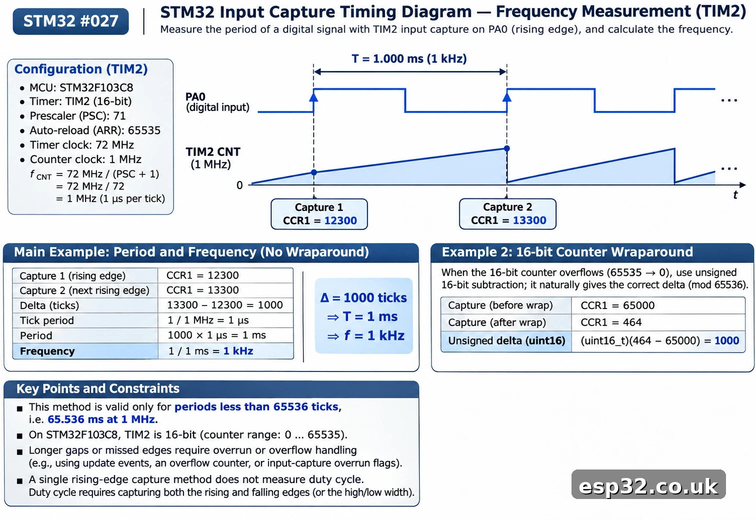
Timer input capture is different from a software GPIO edge interrupt. In capture mode, a selected signal edge causes the hardware to copy the current counter value into a channel’s CCR register. The CPU may service the interrupt a few microseconds later, but the captured counter value represents the timer instant of the edge, not the instant the callback began. That is why input capture is appropriate for pulse frequency, pulse period and, with a suitable two-edge method, duty measurement.
This tutorial’s first input-capture example measures rising-edge to rising-edge period on PA0 / TIM2_CH1. We intentionally do not label it a complete duty-cycle meter: measuring high time requires falling-edge information as well. An advanced input-capture setup can use two channels and the timer’s PWM-input/reset mode; it is not automatically enabled by selecting one input-capture channel. For a short frequency test, successive rising edges are simpler and easier to debug.
Configure TIM2 for 1 µs timestamp resolution
Create a separate TIM2 capture project or disable the earlier TIM2 update-period example before changing TIM2’s configuration. Reuse the 72 MHz timer clock, but set PSC = 71 and ARR = 65535. In TIM2 channel 1 choose Input Capture Direct Mode, Rising Edge, and an initial input filter of zero for a clean logic signal. Select input prescaler DIV1 so every rising edge is captured. Enable the TIM2 global interrupt in NVIC. CubeMX should select PA0 as TIM2_CH1 with no alternate-function remapping.
| Item | Input-capture configuration |
|---|---|
| Timer | TIM2 |
| Capture channel | CH1, direct input |
| MCU pin | PA0 |
| Counter prescaler | 71 |
| Counter period | 65535 |
| Timer count rate | 1 MHz / 1 µs per count |
| Edge polarity | Rising |
| Input prescaler | DIV1, capture every edge |
| Input filter | 0 initially, clean digital loopback |
| Interrupt | TIM2 global interrupt enabled |
At this setting a 16-bit counter wraps after 65,536 ticks, or 65.536 ms. The capture code below calculates the difference between consecutive 16-bit timestamps using unsigned subtraction; that correctly handles a single wrap provided the actual interval between captures is strictly shorter than 65.536 ms. This covers the internal 1 kHz PWM demonstration, where each period is about 1,000 ticks. It does not produce trustworthy results for 1 Hz pulses or for a signal that disappears for a long time. Later sections explain the longer-period alternatives.
HAL input-capture code
Generate code with TIM2 channel 1 in input-capture mode and NVIC enabled, then add this application logic to the main.c USER CODE sections. The first_capture flag ignores the first timestamp because no earlier reference exists. The interrupt stores a period in ticks; the foreground computes and displays or logs frequency later. No blocking UART transmit, printf() or HAL_Delay() is called inside the interrupt.
/* USER CODE BEGIN PV */
static volatile uint16_t previous_capture = 0;
static volatile uint32_t period_ticks = 0;
static volatile uint32_t capture_events = 0;
static volatile uint8_t first_capture = 1;
/* USER CODE END PV */

/* USER CODE BEGIN 2 */
if (HAL_TIM_IC_Start_IT(&htim2, TIM_CHANNEL_1) != HAL_OK) {
    Error_Handler();
}
/* USER CODE END 2 */

/* USER CODE BEGIN 4 */
void HAL_TIM_IC_CaptureCallback(TIM_HandleTypeDef *htim)
{
    if (htim->Instance == TIM2 &&
        htim->Channel == HAL_TIM_ACTIVE_CHANNEL_1) {
        uint16_t now = (uint16_t)HAL_TIM_ReadCapturedValue(
            htim, TIM_CHANNEL_1);

        if (first_capture == 0U) {
            uint16_t delta = (uint16_t)(now - previous_capture);
            if (delta != 0U) {                 // Ignore zero-length result
                period_ticks = (uint32_t)delta;
                capture_events++;
            }
        } else {
            first_capture = 0U;
        }
        previous_capture = now;
    }
}
/* USER CODE END 4 */

/* Example foreground calculation, not inside the callback */
uint32_t ticks = period_ticks;
if (ticks != 0U) {
    uint32_t frequency_hz = 1000000UL / ticks;
    /* Publish frequency_hz to your UI / log here. */
}
HAL_TIM_ReadCapturedValue() returns the capture/compare register corresponding to the selected channel. Testing htim->Instance matters when a project uses multiple timers; checking htim->Channel matters when more than one capture channel is enabled. The timer IRQ handler must invoke HAL_TIM_IRQHandler(&htim2) as generated by CubeMX. Timer functions and callbacks are documented by ST’s STM32F1 HAL timer driver.
At a known 1 kHz input waveform, the expected rising-edge difference is about 1,000 ticks at 1 MHz. The integer expression 1000000 / 1000 then reports 1000 Hz. The sample code deliberately truncates any fractional hertz, uses only the most recently captured interval, and assumes a stable 1 MHz tick clock. For a noisy signal or a frequency estimate requiring fine resolution, average several complete periods in the foreground and handle missed edges and counter overcapture explicitly.
Input capture is not a general-purpose voltage measurement
PA0 must be driven by a valid logic-level signal between the board’s ground and its permitted digital input levels. Do not connect a car injector line, a 12 V Hall sensor, mains wiring or a 5 V pulse generator directly without checking electrical ratings and designing a suitable input-conditioning stage. PA0 is also an ADC-capable pin, and its analog-input function must not be confused with a blanket 5 V tolerance. A timer can timestamp edges accurately and still be permanently damaged by an unsafe voltage.
For an external sensor with an open-collector or open-drain output, use a pull-up to the permitted logic rail, not an assumed pull-up to a higher voltage. For a long cable, add appropriate protection and filtering, consider a Schmitt trigger or comparator, and check sensor ground reference. Timer capture cannot correct poor edges, ground shifts, ringing or excessive EMI.
Understanding wraparound, overcapture and missing edges
The greatest hidden limitation of the simple capture example is its short 16-bit time window. With a 1 MHz counter, 65.536 ms is the longest unambiguous interval if you only subtract two captured uint16_t values and do not track overflows. If the actual signal period is 100 ms, there is an entire counter wrap between edges and the calculated period is wrong. Similarly, a channel that receives two edges before firmware processes an earlier capture can show an overcapture indication; merely reading the latest CCR value does not reconstruct the lost event.
You have several design options. The simplest is to slow the timer to 10 kHz by setting PSC = 7199, which produces a 100 µs resolution and extends the wrap period to 6.5536 seconds. This is often sufficient for tachometers and slow sensors. The trade-off is reduced timestamp resolution: a 1 kHz signal gives only 10 timer counts per period, too coarse for accurate frequency estimation. For slower or more variable signals, use a timer-overflow extension, measure several cycles, or choose a genuinely 32-bit timer on a different STM32 part that supplies one.
A software overflow extension needs careful handling. An update callback may increment an overflow counter while capture happens close to the counter wrap, creating an ambiguity about whether the overflow belongs before or after that captured edge. A reliable implementation must inspect status and capture flags and account for the race condition; combining an update counter with CCR1 naively is not guaranteed to be correct. For an application with strict timing requirements, prefer a properly documented reference implementation, hardware reset-mode measurement, or a higher-width counter.
Input-capture filtering is another trade-off. The timer can sample and filter input edges to reject short glitches, but a filter changes which transitions qualify as edges and imposes minimum pulse-width and timing constraints. Begin with filter zero on a clean test waveform, verify the signal electrically, then configure an appropriate filter based on the application and RM0008’s digital filter description. Using a large filter just to hide wiring problems can suppress real pulses.
Measure duty cycle and pulse width correctly
A full PWM measurement requires both a period and a high-time measurement. The two relevant edges are rising-to-rising for the period and rising-to-falling for the high interval. TIM2 can support a dedicated PWM input mode in which one physical input is routed to paired capture channels with opposite edge polarity, often combined with slave reset mode. That configuration automatically restarts the counter on a selected edge and measures different parts of the waveform. It is more robust for repetitive PWM signals than repeatedly changing a single channel’s polarity in software.
For our 1 kHz, 25% duty TIM3 waveform, the expected period is about 1,000 µs and the expected high time is about 250 µs. Duty cycle is 100 × high_time / period, or 25%. A single-channel rising-edge capture example only produces the first quantity. If a web tutorial claims to show input capture duty cycle but never samples a falling edge, its duty result is not actually measured. This distinction is particularly important for servo pulses, fan tachometry and pulse-width-encoded sensors.
A future esp32.co.uk/ project can extend this tutorial with full PWM-input mode, overflow-aware low-frequency measurements and DMA capture. For this article, the simpler one-channel code offers a reproducible baseline without pretending to solve every corner case. Once it is working, move to the more advanced mode with the exact STM32F1 timer trigger mapping and callback behaviour documented and tested on the target hardware.
Choosing polling, interrupts or DMA for timer results
Timer hardware operates without the CPU even when you do not enable an interrupt. The question is what to do with the events. Polling examines status flags or reads counter registers when convenient; it is useful for slow diagnostics but can miss short-lived events. Interrupts invoke application code on update, capture or compare events; this is a good default for modest event rates. DMA can transfer captured register values to a memory buffer with lower per-event CPU overhead where the timer/channel and DMA mapping support it.
For a one-second scheduler, use a periodic interrupt, keep its callback short and place expensive work in the foreground or an RTOS task. For a continuously running 1 kHz PWM signal, use hardware PWM with no periodic CPU interrupt. For a low- or moderate-rate external signal, input capture with a lightweight IRQ is straightforward. For fast encoders, input events or large timestamp streams, evaluate DMA, buffer ownership and overrun behaviour rather than sending every capture through a heavy callback.
| Task | Recommended mechanism | Why |
|---|---|---|
| Run a small task every second | Update interrupt | Simple periodic trigger |
| Generate constant 1 kHz PWM | Timer PWM output | Edges remain hardware-timed |
| Measure a 500 Hz to 10 kHz pulse stream | Input capture + interrupt | Hardware timestamps, manageable rate |
| Record a dense edge stream | Input capture + DMA where supported | Less CPU work per capture |
| Debounce a slow button | Timer tick or elapsed-time logic | Avoid busy-waiting |
| Track very slow external periods | Slower tick or overflow-aware capture | Avoid 16-bit ambiguity |
You can also use a timer’s trigger output to start ADC conversions at evenly spaced intervals. That is often preferable to launching ADC conversions from a while (1) loop. In a larger STM32 control project, consider the interaction of timer, ADC and DMA carefully: the same DMA channel cannot be allocated incompatibly to multiple active peripherals.
The difference between a timer event, an IRQ and a callback
STM32 timer terminology can initially look redundant. An update event occurs in the timer peripheral when the counter reaches its configured boundary or when certain configuration actions force an update. An interrupt request is signalled only if the corresponding interrupt enable and relevant status conditions permit it. The NVIC routes that IRQ to the Cortex-M3, and the generated IRQ handler calls the HAL dispatcher. Finally, the HAL dispatcher invokes the relevant weak callback that your user code overrides.
This chain means that a timer can be counting perfectly even though your callback never runs. Check the clock, counter enable bit and update flag first; then check interrupt enable, NVIC, the generated handler and the function signature. You can inspect TIM2’s CNT and SR registers under the debugger, although pausing the core may affect its timing. If you call HAL_TIM_Base_Start(&htim2) without _IT, you start the timer without enabling its base update interrupt; the periodic callback will not be generated by that call.
For TIM2 input capture, the pathway is analogous but uses the relevant CC1 event and HAL_TIM_IC_CaptureCallback(), not the base period elapsed callback. When a single timer is configured for more than one type of event, protect against confusion by checking both htim->Instance and, for capture, the active channel. ST’s HAL code documents the dispatcher and callback signatures, while RM0008 documents the underlying DIER, SR and CCR registers.
Troubleshooting a timer that appears not to work
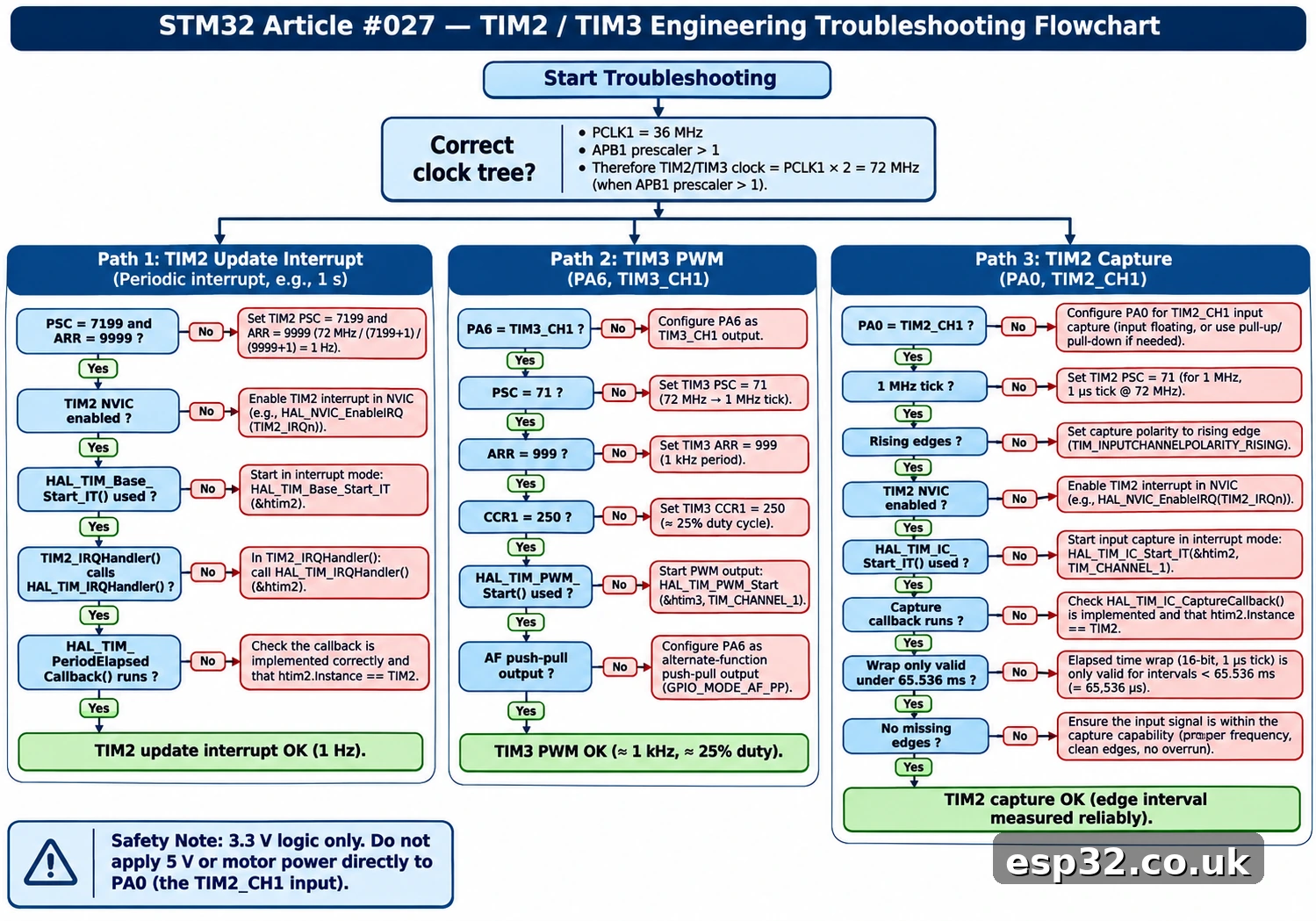
The first step is to separate clock, pin, event and application-code problems. If a one-second timer fires every two seconds, suspect clock configuration before interrupt latency. If a PWM pin does not toggle, check the channel output and alternate-function routing. If capture gives a constant value, confirm that edges actually reach the correct input pin, that the correct polarity is selected, and that IRQ handling is enabled.
| Symptom | Likely cause | Practical check |
|---|---|---|
| Interrupt never fires | NVIC disabled, handler missing, wrong start API | Enable TIM2 global IRQ; HAL_TIM_Base_Start_IT; inspect TIM2_IRQHandler |
| Timer runs 2× too fast or slow | Confused PCLK with timer clock | APB prescaler >1 implies timer clock ×2 on F103 |
| One-second example takes nine seconds | Running at 8 MHz rather than 72 MHz | Inspect SystemClock_Config() and actual PLL source |
| PWM output stuck high/low | Incorrect channel mode, GPIO AF or CCR | Check PA6 TIM3_CH1, HAL_TIM_PWM_Start, pulse, polarity |
| No capture callbacks | PA0 wrong pin/AF, no edges or NVIC disabled | Check input waveform, direct CH1, rising polarity, TIM2 IRQ |
| Captured frequency implausibly high | Missing pulses, capture too close, wrong clock | Inspect raw period_ticks, signal edge quality and timer frequency |
| Captured frequency implausibly low | Extra glitches, input bounce, bad filtering | Scope signal; adjust pull-up, protection and filter |
| Slow input measures incorrectly | 16-bit counter wraps between edges | Reduce tick frequency or implement overflow-aware capture |
| Periodic timer works, capture does not | Configurations mixed | Do not run two incompatible TIM2 initialization modes in one project |
| Works until other peripheral enabled | Pin or DMA-resource conflict | Inspect CubeMX pinout and resource allocation |
Debugger and timing measurement cautions
A breakpoint is an excellent way to show that a callback is invoked but a poor measurement instrument for precise timer timing. Depending on debug freeze configuration, some timers continue counting while the CPU is halted and others are stopped. The result may differ across boards and projects. For PWM, observe the output with a scope or logic analyser if possible. For an update timer, record a sequence of timestamps with a nonblocking log mechanism or toggle a separate output pin from a minimal callback, accepting that the observed pin edge has interrupt latency and jitter.
A basic multimeter can sometimes display the average of a PWM output, but it may not reveal the true duty cycle or frequency. A logic analyser makes edge timing visible and can reveal unexpected spikes caused by wiring. If a test input comes from another powered board, connect common ground only where electrically safe and check the voltage domain. The internal PA6-to-PA0 loopback is particularly helpful because it removes many external uncertainties before testing a real sensor.
Frequently asked STM32 timer questions
Is TIM2 always a 32-bit timer?
No. STM32F103C8 TIM2 is 16-bit. Many later STM32 families have a 32-bit TIM2, but peripheral width is device-specific. On this Blue Pill, 16-bit capture wraps at 65536 counts; design the clock divider and measurement window accordingly. Device-family assumptions are a surprisingly common source of firmware porting bugs.
Why does a TIM2 timer use 72 MHz when APB1 is 36 MHz?
The STM32F1 timer clock multiplier is applied when the APB1 prescaler is not one. In the example clock tree, APB1 is divided by two, so PCLK1 = 36 MHz but the TIM2 clock = 72 MHz. If you select APB1 prescaler one, the timer clock equals PCLK1. Always recalculate from the actual RCC setup instead of memorizing one number.
Does HAL_TIM_Base_Start_IT automatically configure the NVIC?
No. It starts the timer and enables the appropriate timer interrupt at the peripheral level; the NVIC, interrupt priority and IRQ handler must already be configured appropriately, usually by CubeMX. An interrupt callback without the corresponding handler call will not work.
Can I capture a 5 V square wave on PA0?
Do not assume so. The PA0 analog-capable pin and the F103’s input characteristics do not make it generally safe to apply arbitrary 5 V signals. Use a properly designed level translator or conditioning circuit for signals outside the allowed range, and consult the exact datasheet. Common ground and transient protection also matter.
Why does my PWM duty change but the frequency stay the same?
That is the purpose of the CCR register in PWM mode. ARR and PSC primarily determine the period, while CCR controls when the output compares against the counter. Changing CCR without changing PSC or ARR changes duty without intentionally changing frequency. Some preload settings delay the change until an update event.
Do I need an interrupt for PWM or capture?
Hardware PWM needs no interrupt once started. Input capture can also latch timestamps without an interrupt, but firmware must retrieve them somehow. Interrupt-driven capture is convenient for modest rates; DMA-based capture may be preferable at higher rates. Choosing the method depends on throughput, jitter limits and buffering requirements.
What is the difference between SysTick and TIM2?
SysTick is part of the Cortex-M3 core and commonly supplies the HAL tick in a standard STM32Cube project. TIM2 is a separate general-purpose STM32 peripheral with input capture and compare channels that SysTick does not provide. If you reconfigure a timer as the HAL time base in a custom project, take care not to reuse it for an unrelated application without understanding conflicts.
Recommended next steps
Start by validating the one-second TIM2 update example, with the correct APB1 timer clock and short callback. Next, use TIM3 on PA6 to produce a known 1 kHz waveform and verify it with a logic analyser or an appropriate input test. Then move to the separate TIM2 capture configuration on PA0 and check that the measured delta is about 1,000 counts. Only after these fundamentals work should you add noisy sensors, low-frequency overflow handling or a full two-edge PWM-input measurement.
For related fundamentals, see the esp32.co.uk/ guides on STM32 GPIO and HAL LED programming, STM32 UART communication, and STM32 ADC and DMA. Those are on-site search links rather than unverified article permalink guesses. Timer-driven ADC sampling and DMA capture are natural extensions of the same hardware ideas.
Official references and scope
This esp32.co.uk/ article is grounded in ST's RM0008 STM32F1 reference manual, AN4013 introduction to STM32 timers, and the STM32F1 HAL timer source. The pin mappings and calculations have been checked against the published reference material, but the sample code has not been compiled or bench-tested in this session. Verify the actual CubeMX-generated configuration and waveform on your board before relying on it in a safety-critical or production application.