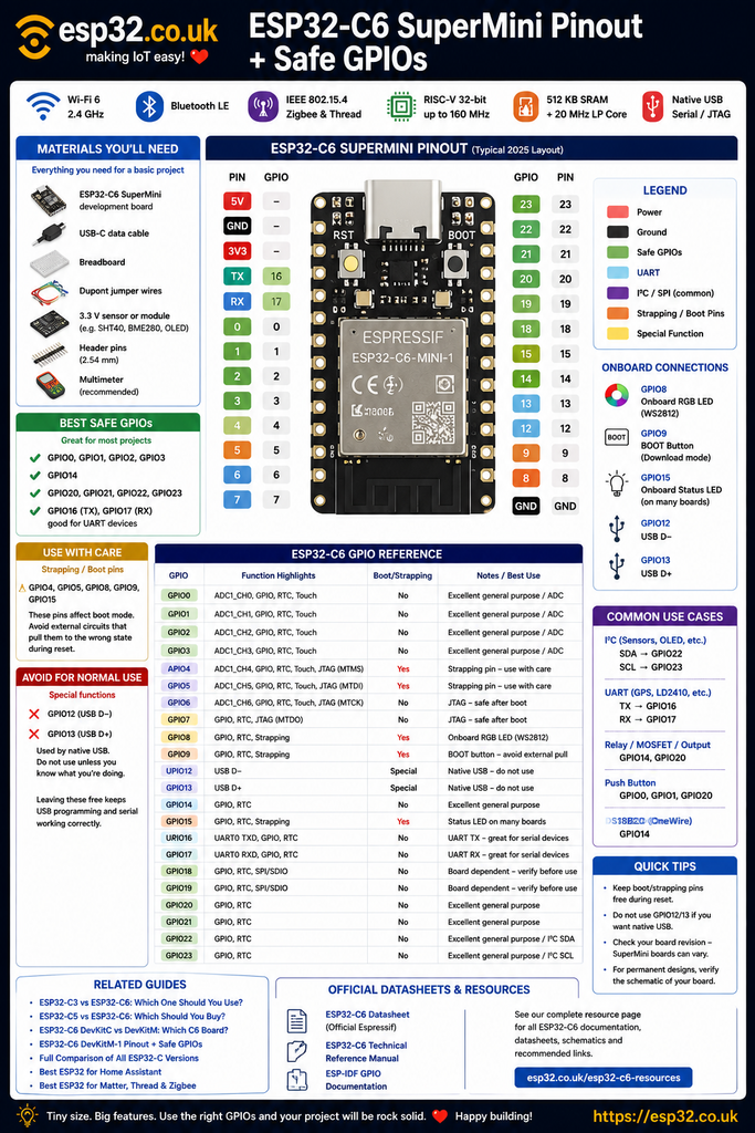
The ESP32-C6 SuperMiniAliExpress price is one of the smallest ways to get Wi-Fi 6, Bluetooth LE, Zigbee and Thread in an ESP32AliExpress price project. On the common SuperMini layout, the easiest GPIOs to start with are GPIO0, GPIO1, GPIO2, GPIO3, GPIO14, GPIO20, GPIO21, GPIO22 and GPIO23. GPIO16/17 are also useful when UART0 is not needed. GPIO4, GPIO5, GPIO8, GPIO9 and GPIO15 are ESP32-C6AliExpress price strapping pins, GPIO8 is normally connected to the onboard RGB LED, GPIO9 is connected to BOOT, GPIO15 commonly drives the onboard status LED, and GPIO12/13 are used by native USB. Because “SuperMini” is a third-party board format rather than an official Espressif board, small hardware differences exist between suppliers, so always compare the markings on the actual board before soldering a final design. Espressif officially identifies GPIO4, GPIO5, GPIO8, GPIO9 and GPIO15 as ESP32-C6AliExpress price strapping pins. (documentation.espressif.com)
Materials You’ll Need
For a basic ESP32-C6 SuperMiniAliExpress price project, the most useful parts are:
| Item | Why you need it |
|---|---|
| ESP32-C6 SuperMini development board | Main microcontroller board |
| USB-C data cable | Programming and power |
| 2.54 mm header pins | For breadboard or jumper-wire use |
| Breadboard | Easy prototyping |
| Dupont jumper wires | Connecting sensors and modules |
| 3.3 V-compatible sensor or module | For testing GPIO/I²C/SPI |
| Multimeter | Useful for checking power and wiring |
| Optional level shifter | Required for some 5 V logic devices |
The ESP32-C6 itself uses 3.3 V GPIO logic. Do not feed 5 V directly into a GPIO.
For a first practical test, an inexpensive I²C sensor such as an SHT40, BME280 or OLED display is ideal because only four connections are required.
What is the ESP32-C6 SuperMini?
The ESP32-C6 SuperMini is a compact third-party development board built around Espressif’s ESP32-C6.
Typical boards provide:
- 32-bit RISC-V CPU
- up to 160 MHz main processor
- 20 MHz low-power RISC-V processor
- 512 KB high-performance SRAM
- Wi-Fi 6 at 2.4 GHz
- Bluetooth Low Energy
- IEEE 802.15.4
- Zigbee
- Thread
- USB-C
- native USB Serial/JTAG
- ADC
- I²C
- SPI
- UART
- PWM
- onboard LEDs
- BOOT and RESET buttons
The common board is only around 22–25 mm long and roughly 18–20 mm wide, depending on manufacturer.
That makes it particularly attractive for:
- Home Assistant sensors
- Zigbee devices
- Thread devices
- Matter experiments
- small ESPHome nodes
- embedded controllers
- battery projects
- 3D-printed enclosures
The ESP32-C6 itself combines Wi-Fi 6, Bluetooth LE and an IEEE 802.15.4 radio on the same chip.
Important: SuperMini is not one official board
There is no single official Espressif ESP32-C6 SuperMini specification.
“SuperMini” describes a compact third-party board format manufactured by several vendors.
Most current boards use essentially the same layout, but differences can include:
- regulator
- USB circuitry
- flash configuration
- charging circuitry
- LEDs
- antenna
- exact PCB size
- silkscreen
- exposed pads
This is why some internet pinout diagrams disagree.
The GPIO functions in this article are based on the common 2025/2026 C6 SuperMini layout, combined with Espressif’s official ESP32-C6 GPIO restrictions.
For a permanent PCB design, verify the exact SuperMini board being purchased before designing around it.
Quick safe GPIO cheat sheet
For most projects, start here:
Best general-purpose GPIOs
GPIO0
GPIO1
GPIO2
GPIO3
GPIO14
GPIO20
GPIO21
GPIO22
GPIO23
These are the easiest pins for:
- buttons
- relays
- LEDs
- digital sensors
- interrupts
- PWM
- I²C
- SPI
Also useful
GPIO16
GPIO17
These are UART0 TX/RX by default, so they are excellent for serial peripherals but may interfere with UART logging if reused.
Use with care
GPIO4
GPIO5
GPIO6
GPIO7
GPIO8
GPIO9
GPIO15
GPIO4, 5, 8, 9 and 15 have boot/strapping roles.
GPIO6 and GPIO7 are associated with JTAG functions.
Avoid for normal projects when using USB
GPIO12
GPIO13
These are the native USB data pins.
Common ESP32-C6 SuperMini pinout
A typical C6 SuperMini exposes approximately the following pins.
| Board marking | ESP32-C6 GPIO | Main notes |
|---|---|---|
| 5V | — | USB/external 5 V rail |
| GND | — | Ground |
| 3V3 | — | Regulated 3.3 V |
| TX | GPIO16 | UART0 TX |
| RX | GPIO17 | UART0 RX |
| 0 | GPIO0 | ADC, safe general GPIO |
| 1 | GPIO1 | ADC, safe general GPIO |
| 2 | GPIO2 | ADC, safe general GPIO |
| 3 | GPIO3 | ADC, safe general GPIO |
| 4 | GPIO4 | ADC, strapping, JTAG |
| 5 | GPIO5 | ADC, strapping, JTAG |
| 6 | GPIO6 | ADC, JTAG |
| 7 | GPIO7 | JTAG |
| 8 | GPIO8 | Strapping + onboard RGB LED |
| 9 | GPIO9 | Strapping + BOOT |
| 12 | GPIO12 | USB D− |
| 13 | GPIO13 | USB D+ |
| 14 | GPIO14 | Good general GPIO |
| 15 | GPIO15 | Strapping + status LED on many boards |
| 18 | GPIO18 | General/peripheral functions; verify board revision |
| 19 | GPIO19 | General/peripheral functions; verify board revision |
| 20 | GPIO20 | Good general GPIO |
| 21 | GPIO21 | Good general GPIO |
| 22 | GPIO22 | Good general GPIO |
| 23 | GPIO23 | Good general GPIO |
Common SuperMini boards additionally connect an RGB LED to GPIO8 and BOOT to GPIO9. The exact board-level mapping should still be checked because SuperMini hardware is produced by multiple vendors. (mischianti.org)
The genuinely important boot pins
The official ESP32-C6 strapping GPIOs are:
GPIO4
GPIO5
GPIO8
GPIO9
GPIO15
Espressif samples these pins during reset to configure low-level chip behaviour. (Espressif Systems)
That does not mean these GPIOs can never be used.
It means external circuitry must not force them to an inappropriate state while the ESP32-C6 is starting.
Typical problematic circuits include:
- strong pull-up resistors
- strong pull-down resistors
- relay modules
- external microcontrollers
- sensors that actively drive the line during reset
After startup, these pins can normally be used as GPIOs.
GPIO9: the BOOT pin
GPIO9 deserves special attention because the SuperMini normally connects it to the BOOT button.
Holding GPIO9 LOW during reset causes the ESP32-C6 to enter firmware download mode.
Conceptually:
GPIO9 normal
→ run firmware

GPIO9 LOW during reset
→ download/programming mode
If a peripheral permanently pulls GPIO9 LOW, the board may appear to stop booting.
Symptoms include:
- sketch never starts
- serial bootloader waits for upload
- board only works when the peripheral is removed
For ordinary sensors and outputs, use another GPIO.
GPIO8: onboard RGB LED
On most C6 SuperMini boards, GPIO8 drives a small WS2812-compatible addressable RGB LED.
GPIO8 is also a strapping pin.
That makes it useful for status indication but a poor first choice for an unrelated external circuit.
The onboard RGB LED can normally be controlled with libraries such as:
- Adafruit NeoPixel
- FastLED
A simple Arduino example is:
#include <Adafruit_NeoPixel.h>

#define RGB_PIN 8

Adafruit_NeoPixel pixel(
  1,
  RGB_PIN,
  NEO_GRB + NEO_KHZ800
);

void setup() {
  pixel.begin();

  pixel.setPixelColor(
    0,
    pixel.Color(0, 50, 0)
  );

  pixel.show();
}

void loop() {
}
If the RGB LED behaves strangely during boot, remember that GPIO8 also participates in ESP32-C6 startup configuration.
GPIO15: status LED and strapping
Many SuperMini versions also connect a conventional onboard status LED to:
GPIO15GPIO15 is also a strapping pin.
It can be used after startup, but external circuitry should not interfere with its reset state.
If an ordinary output pin is required, GPIO14, 20, 21, 22 or 23 is cleaner.
GPIO4 and GPIO5
GPIO4 and GPIO5 are both:
- ADC capable
- general-purpose GPIO capable
- low-power-domain capable
but they are also ESP32-C6 strapping pins.
They additionally carry JTAG functions:
GPIO4 → MTMS
GPIO5 → MTDI
They can still be useful once the boot requirements are understood.
For beginners, however:
GPIO0–3
GPIO14
GPIO20–23
are simpler.
GPIO6 and GPIO7
GPIO6 and GPIO7 are not ESP32-C6 strapping pins, despite some SuperMini pinout diagrams incorrectly grouping them with boot pins.
Their important special role is JTAG:
GPIO6 → MTCK
GPIO7 → MTDO
Espressif distinguishes these from the actual strapping pins GPIO4, GPIO5, GPIO8, GPIO9 and GPIO15. (documentation.espressif.com)
If JTAG debugging is not being used, GPIO6 and GPIO7 can often be reused.
For a first project, though, the totally uncomplicated GPIOs remain preferable.
GPIO12 and GPIO13: native USB
These two pins deserve another clear warning:
GPIO12 → USB D−
GPIO13 → USB D+
They form the ESP32-C6’s built-in USB Serial/JTAG connection. (Espressif Systems)
This is how tiny boards such as the SuperMini can provide USB-C programming without needing a separate CP2102 or CH340 serial converter.
GPIO12 and GPIO13 can technically be reassigned as normal GPIOs.
But doing so disables native USB functionality.
That can affect:
- USB serial monitor
- USB programming
- JTAG
- firmware recovery
For normal projects:
leave GPIO12 and GPIO13 alone.
There are enough other pins available.
GPIO16 and GPIO17: UART0
The pads commonly marked:
TX
RX
map to:
TX → GPIO16
RX → GPIO17
This matches the default ESP32-C6 UART0 assignment.
They are useful for devices such as:
Example:
HardwareSerial SensorSerial(0);

void setup() {
  SensorSerial.begin(
    115200,
    SERIAL_8N1,
    17,
    16
  );
}

void loop() {
}
Remember:
Peripheral TX → ESP32 RX
Peripheral RX → ESP32 TX
ADC pins
The ESP32-C6 provides seven ADC1 channels:
| GPIO | ADC channel |
|---|---|
| GPIO0 | ADC1_CH0 |
| GPIO1 | ADC1_CH1 |
| GPIO2 | ADC1_CH2 |
| GPIO3 | ADC1_CH3 |
| GPIO4 | ADC1_CH4 |
| GPIO5 | ADC1_CH5 |
| GPIO6 | ADC1_CH6 |
This is a welcome improvement over the original ESP32’s awkward ADC1/ADC2 Wi-Fi conflict.
For a simple analog input, the cleanest choices are:
GPIO0
GPIO1
GPIO2
GPIO3
because GPIO4 and GPIO5 are strapping pins and GPIO6 also has a JTAG role.
Typical uses include:
- potentiometers
- analog light sensors
- voltage dividers
- analog pressure sensors
- battery monitoring
Never exceed the permitted ESP32 ADC input voltage.
Best analog GPIOs
For an analog sensor:
first choice: GPIO0–GPIO3
Example:
const int sensorPin = 0;

void setup() {
  Serial.begin(115200);
}

void loop() {
  int reading = analogRead(sensorPin);

  Serial.println(reading);

  delay(500);
}
GPIO0–GPIO3 are particularly convenient because they avoid the major USB, onboard LED and boot conflicts.
I²C pins
Unlike an old Arduino Uno, the ESP32-C6 does not force I²C onto one fixed pair of external GPIOs.
The GPIO matrix allows I²C signals to be routed to suitable pins.
A clean SuperMini choice is:
SDA → GPIO22
SCL → GPIO23
For example:
#include <Wire.h>

void setup() {
  Wire.begin(22, 23);
}

void loop() {
}
This is a good combination for:
GPIO22/23 have none of the major boot, LED or USB complications.
ESPHome I²C example
For ESPHome:
i2c:
  sda: GPIO22
  scl: GPIO23
  scan: true
Then a sensor can be added normally.
For example:
sensor:
  - platform: sht4x
    temperature:
      name: "Room Temperature"

    humidity:
      name: "Room Humidity"
That creates an extremely compact:
ESP32-C6 SuperMini
+
SHT40/SHT45
Home Assistant environmental sensor.
SPI pins
SPI is also flexible because of the ESP32-C6 GPIO matrix.
A practical set of uncomplicated pins could be:
SCK  → GPIO23
MOSI → GPIO22
MISO → GPIO21
CS   → GPIO14
The exact mapping can be selected in software.
This is useful for:
- TFT displays
- external ADCs
- radio modules
- SD cards
- SPI sensors
Avoid blindly copying the default SPI pins from an ESP32 DevKit or ESP32-C3 tutorial.
The C6 is a different chip and the SuperMini is a different board.
Best GPIO for a relay
A relay input should ideally avoid boot pins.
Good choices include:
GPIO14
GPIO20
GPIO21
GPIO22
GPIO23
For example:
#define RELAY_PIN 14

void setup() {
  pinMode(RELAY_PIN, OUTPUT);
  digitalWrite(RELAY_PIN, LOW);
}

void loop() {
}
A relay coil itself must not be powered directly from the ESP32 GPIO.
Use:
- a proper relay module
- transistor driver
- MOSFET driver
depending on the hardware.
Best GPIO for a pushbutton
Good button pins include:
GPIO0
GPIO1
GPIO2
GPIO3
GPIO14
GPIO20
GPIO21
GPIO22
GPIO23
Example:
#define BUTTON_PIN 20

void setup() {
  pinMode(
    BUTTON_PIN,
    INPUT_PULLUP
  );
}

void loop() {
  if (!digitalRead(BUTTON_PIN)) {
    // button pressed
  }
}
Avoid GPIO9 unless the button is deliberately intended to behave like the board’s BOOT button.
Best GPIO for a DS18B20
OneWire works well on a general-purpose GPIO.
A good choice is:
GPIO14Typical wiring:
3.3V
 │
4.7kΩ
 │
 ├──── GPIO14
 │
DS18B20 DATA
That keeps the OneWire sensor away from USB and boot pins.
Best GPIO for a mmWave sensor
For a UART radar such as:
the obvious pair is:
GPIO16 → TX
GPIO17 → RX
Example:
Radar TX → GPIO17
Radar RX → GPIO16
This uses the ESP32-C6’s normal UART0 pins.
If USB serial debugging is preferred, another UART can be routed through different GPIOs.
Best pins for PWM
Most normal output-capable ESP32-C6 GPIOs can be used for PWM through the LEDC peripheral.
Clean choices include:
GPIO14
GPIO20
GPIO21
GPIO22
GPIO23
Useful applications include:
- LED dimming
- MOSFET control
- fan control
- buzzers
- motor drivers
For a 4-wire PC fan, for example, GPIO14 would be an excellent PWM-control GPIO.
GPIO recommendations table
| GPIO | Recommendation | Main reason |
|---|---|---|
| GPIO0 | ✅ Excellent | ADC + general GPIO |
| GPIO1 | ✅ Excellent | ADC + general GPIO |
| GPIO2 | ✅ Excellent | ADC + general GPIO |
| GPIO3 | ✅ Excellent | ADC + general GPIO |
| GPIO4 | ⚠️ Care | Strapping + JTAG |
| GPIO5 | ⚠️ Care | Strapping + JTAG |
| GPIO6 | 🟡 Good with care | ADC + JTAG |
| GPIO7 | 🟡 Good with care | JTAG |
| GPIO8 | ⚠️ Avoid first | RGB LED + strapping |
| GPIO9 | ⚠️ Avoid | BOOT + strapping |
| GPIO12 | ❌ Avoid | USB D− |
| GPIO13 | ❌ Avoid | USB D+ |
| GPIO14 | ✅ Excellent | Clean general I/O |
| GPIO15 | ⚠️ Care | Strapping + status LED |
| GPIO16 | 🟡 Good | UART0 TX |
| GPIO17 | 🟡 Good | UART0 RX |
| GPIO18 | 🟡 Verify board | Board-dependent use |
| GPIO19 | 🟡 Verify board | Board-dependent use |
| GPIO20 | ✅ Excellent | Clean general I/O |
| GPIO21 | ✅ Excellent | Clean general I/O |
| GPIO22 | ✅ Excellent | Clean general I/O |
| GPIO23 | ✅ Excellent | Clean general I/O |
Why GPIO18 and GPIO19 deserve a note
This is one of the areas where SuperMini information online becomes inconsistent.
ESP32-C6 supports several alternative SPI/SDIO functions on GPIO18 and GPIO19, and different bare-chip/flash configurations can use resources differently.
Because SuperMini boards are third-party designs, do not assume every revision is electrically identical.
For a hobby prototype, GPIO18/19 may work perfectly on a particular board.
For a design that will be manufactured repeatedly:
use GPIO0–3, GPIO14 or GPIO20–23 first, and verify the exact SuperMini schematic before relying on GPIO18/19.
That avoids a large amount of unnecessary uncertainty.
The best GPIOs to remember
If there is only one section worth bookmarking, it is this:
Start here
GPIO0
GPIO1
GPIO2
GPIO3
GPIO14
GPIO20
GPIO21
GPIO22
GPIO23
UART
GPIO16 TX
GPIO17 RX
ADC
GPIO0–GPIO6Prefer:
GPIO0–GPIO3for uncomplicated analog projects.
Boot/strapping pins
GPIO4
GPIO5
GPIO8
GPIO9
GPIO15
Native USB
GPIO12 D-
GPIO13 D+
Onboard hardware
GPIO8  → RGB LED
GPIO9  → BOOT
GPIO15 → status LED on many boards
Arduino IDE setup
Current Arduino-ESP32 versions support the ESP32-C6.
A common configuration is:
Board:
ESP32C6 Dev Module
Then enable:
USB CDC On Boot
→ Enabled
if native USB serial output is required.
Typical settings for a common 4 MB SuperMini are:
Board:
ESP32C6 Dev Module

Flash Size:
4MB

USB CDC On Boot:
Enabled
Do not assume every SuperMini has the same flash capacity.
Check the listing or actual chip/board before selecting a larger flash size.
Basic Blink test
Because GPIO8 is normally connected to an addressable RGB LED rather than a simple conventional LED, it is often easier to test a free GPIO with an external LED.
For example, connect:
GPIO14
→ 220–470Ω resistor
→ LED
→ GND
Then use:
#define LED_PIN 14

void setup() {
  pinMode(LED_PIN, OUTPUT);
}

void loop() {
  digitalWrite(LED_PIN, HIGH);
  delay(500);

  digitalWrite(LED_PIN, LOW);
  delay(500);
}
This also proves that:
- firmware uploads correctly
- the board boots normally
- GPIO14 works
- the Arduino toolchain is configured correctly
ESPHome setup
A basic ESPHome configuration can use:
esphome:
  name: c6-supermini
  friendly_name: C6 SuperMini

esp32:
  variant: esp32c6
  framework:
    type: esp-idf

logger:

api:

ota:

wifi:
  ssid: !secret wifi_ssid
  password: !secret wifi_password
The exact board: definition supported by the installed ESPHome/PlatformIO version may vary.
Using the correct ESP32-C6 target is more important than assuming a third-party “SuperMini” board definition exists.
Zigbee, Thread and Matter
The main reason to choose a C6 SuperMini instead of a C3 SuperMini is not CPU performance.
Both C3 and C6 have 160 MHz RISC-V main processors.
The C6 adds an:
IEEE 802.15.4 radiowhich enables:
Zigbee
Thread
Matter over Thread
in addition to:
Wi-Fi 6
Bluetooth LE
This makes the board unusually capable for its size.
A single tiny PCB can potentially form the basis of:
- Zigbee temperature sensor
- Thread environmental sensor
- Matter smart switch
- BLE device
- Wi-Fi ESPHome node
depending on firmware.
C6 SuperMini vs C6 DevKitC
The SuperMini is ideal when:
- size matters
- the final project goes inside an enclosure
- only a modest number of GPIOs are required
- low cost matters
The official ESP32-C6-DevKitC-1 is better when:
- maximum GPIO access matters
- breadboard development matters
- official schematics matter
- predictable hardware revisions matter
- debugging matters
The SuperMini is therefore excellent for finished hobby projects, while the DevKitC is often easier during development.
C6 SuperMini vs C3 SuperMini
Choose C3 SuperMini when:
- Wi-Fi 4 is enough
- BLE is enough
- lowest cost matters
- Zigbee/Thread are unnecessary
Choose C6 SuperMini when:
- Wi-Fi 6 is useful
- Zigbee is required
- Thread is required
- Matter experimentation is planned
- more future flexibility is wanted
For a new smart-home sensor, the C6 is usually the more interesting option.
Common problem: board enters download mode every boot
Check GPIO9 first.
Something may be holding:
GPIO9 LOWduring reset.
Disconnect external hardware from GPIO9 and reset again.
Also inspect:
GPIO4
GPIO5
GPIO8
GPIO15
because they are the other ESP32-C6 strapping pins.
Common problem: USB disappears after changing GPIOs
Check whether firmware reassigned:
GPIO12
GPIO13
These are:
USB D-
USB D+
Using them as ordinary GPIO disables native USB Serial/JTAG.
This can make the board appear “dead” even though the firmware itself is still running.
Hold BOOT during reset or reconnect using the appropriate flashing procedure if USB recovery is required.
Common problem: RGB LED won’t behave like a normal LED
The LED on GPIO8 is normally addressable, not simply wired between GPIO and ground.
So this:
digitalWrite(8, HIGH);is not equivalent to controlling a normal single-colour LED.
Use a WS2812/NeoPixel-compatible library.
Also remember that GPIO8 is a strapping pin.
Common problem: ESP32-C6 won’t upload
Try:
- Hold BOOT.
- Press and release RESET.
- Release BOOT.
- Start the upload.
If necessary, hold BOOT while connecting USB.
Then confirm:
ESP32C6 Dev Moduleor the correct C6 board definition is selected.
Also use a genuine USB data cable. Many USB-C cables supplied with chargers contain power conductors but no data connection.
Common problem: board works from USB but not 5 V pin
SuperMini power circuits vary more than official Espressif boards.
Do not assume that:
USB 5V
external 5V
battery
can all be connected simultaneously.
Check the exact PCB before combining power sources.
For a basic project, powering through USB-C is the safest development option.
Common problem: Wi-Fi works but Zigbee examples don’t
The presence of an IEEE 802.15.4 radio does not mean every Arduino or ESPHome build automatically becomes a Zigbee device.
Software support must also provide:
- appropriate radio stack
- Zigbee/Thread libraries
- correct framework configuration
- suitable partitioning
- correct application firmware
The hardware capability is present, but the firmware still has to use it.
Recommended GPIO recipes
SHT40 / BME280 / OLED
SDA → GPIO22
SCL → GPIO23
Relay
GPIO14Button
GPIO20Analog sensor
GPIO0UART sensor
TX → GPIO16
RX → GPIO17
PWM output
GPIO14Extra digital sensors
GPIO20
GPIO21
GPIO22
GPIO23
This leaves all the awkward boot and USB pins untouched.
Suggested beginner pin allocation
For a typical Home Assistant node:
| Function | GPIO |
|---|---|
| I²C SDA | GPIO22 |
| I²C SCL | GPIO23 |
| Relay | GPIO14 |
| Button | GPIO20 |
| Extra digital input | GPIO21 |
| Analog input | GPIO0 |
| UART RX | GPIO17 |
| UART TX | GPIO16 |
This is a very clean starting configuration.
ESP32-C6 Datasheets & Documentation
For readers who want to go deeper, a dedicated ESP32-C6 Datasheets & Resources page on esp32.co.uk should collect the important reference material in one place.
That internal resource page can contain:
- ESP32-C6 datasheet
- ESP32-C6 technical reference manual
- ESP32-C6 GPIO restrictions
- ESP32-C6 strapping-pin table
- ESP32-C6 ADC documentation
- ESP32-C6 Wi-Fi/BLE information
- ESP32-C6 Zigbee/Thread documentation
- common SuperMini schematic
- downloadable esp32.co.uk SuperMini pinout diagram
This allows other articles to link to one internal documentation hub instead of repeatedly sending readers away to external sites.
For manufacturer verification, the key external references are the official ESP32-C6 Datasheet and ESP-IDF GPIO documentation. (documentation.espressif.com)
Related ESP32 Guides
Readers using the ESP32-C6 SuperMini should also see these related guides on esp32.co.uk:
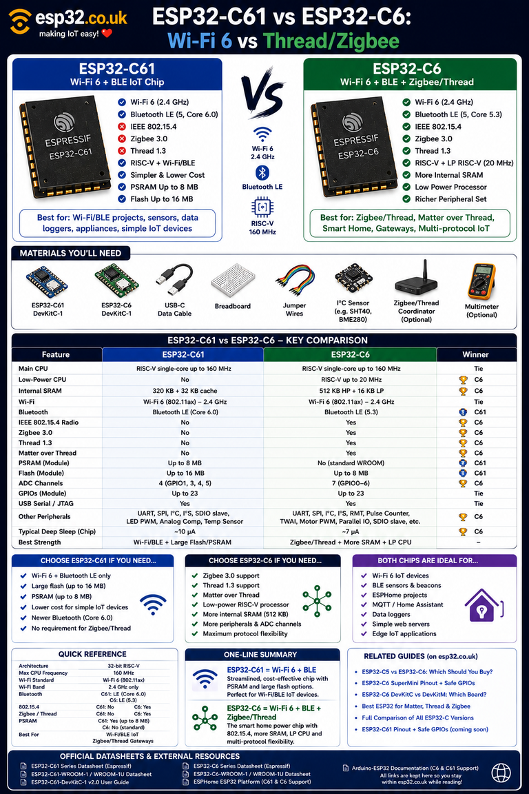
- ESP32-C3 vs ESP32-C6: Which One Should You Use?
- ESP32-C5 vs ESP32-C6: Which Should You Buy?
- ESP32-C6 DevKitC vs DevKitM: Which C6 Board Should You Buy?
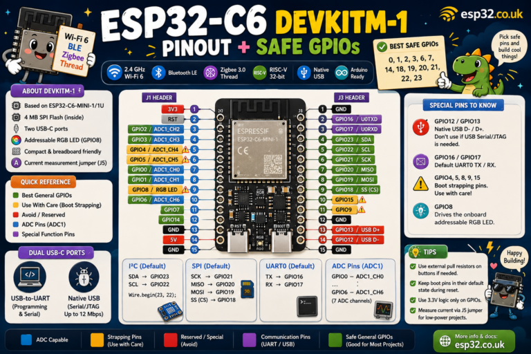
- ESP32-C6 DevKitM-1 Pinout + Safe GPIOs
- Full Comparison of All ESP32-C Versions and Development Boards
- Best ESP32 for Home Assistant
- Best ESP32 for Matter, Thread & Zigbee
These should be linked internally rather than sending readers to third-party comparison sites.
Final recommendation
The ESP32-C6 SuperMini is an unusually powerful board for its size.
For most projects, there is no reason to fight with every available GPIO.
Start with:
GPIO0
GPIO1
GPIO2
GPIO3
GPIO14
GPIO20
GPIO21
GPIO22
GPIO23
Use:
GPIO16 / GPIO17when UART is required.
Keep away from:
GPIO12 / GPIO13if native USB is needed.
And treat:
GPIO4
GPIO5
GPIO8
GPIO9
GPIO15
as boot-sensitive pins.
The most important practical difference between this board and an official Espressif DevKit is not the ESP32-C6 itself — it is the third-party SuperMini PCB surrounding it.
Once the particular board revision has been verified, however, the C6 SuperMini makes an excellent compact platform for:
Wi-Fi 6 + BLE + Zigbee + Thread + Matter projects.