
The Bosch BME680PriceAliExpress price is a combined digital temperature, relative-humidity, barometric-pressure and gas-resistance sensor. It is often sold as a tiny breakout board with just four to seven header pins, but not every BME680AliExpress price module has the same regulator, voltage tolerance or physical header order. This esp32.co.uk/ reference guide focuses on the practical electronics: Adafruit breakout pinout, Bosch chip pinout, I²C address selection, ESP32 I²C/SPI connection tables, gas-heater operation, and a minimal Arduino sketch using the maintained Adafruit BME680AliExpress price library.
Quick setup: On the documented Adafruit BME680 #3660 breakout, connect ESP32 3V3 → VIN, GND → GND, GPIO21 (SDA) → SDI, and GPIO22 (SCL) → SCK. The default 7-bit I²C address is 0x77; pulling SDO to ground selects 0x76. These GPIO choices are for a classic ESP32-WROOM DevKit; other ESP32 boards can use different pins.
Important: A BME680 does not directly report accurate CO₂, VOC concentration in ppm, or a universal IAQ score. Its gas element returns a heated metal-oxide gas resistance in ohms. Index calculations need a separate algorithm, calibration and environmental context; never label the raw reading as CO₂ concentration.
What the BME680 measures and what it does not
| Measurement | Output or limitation |
|---|---|
| Temperature | Temperature in degrees Celsius; measured by the integrated sensor; local heater and PCB heat can affect the reading. |
| Relative humidity | Relative humidity in percent RH, with temperature compensation. |
| Barometric pressure | Absolute ambient pressure, normally reported in Pascals by the Adafruit library; convert to hPa by dividing by 100. |
| Gas sensing | One MOX gas-resistance value in ohms. Changes with the heated sensor, VOC exposure, humidity, temperature, and operating history. |
| Altitude estimate | Derived from measured pressure and a current reference sea-level pressure; not an independent physical measurement. |
| Not included | No direct CO₂ ppm output, no particulate matter measurement, and no automatic gas identification. |
Bosch lists an operating range of approximately −40 to +85 °C, 0–100% relative humidity, and 300–1100 hPa. Normal operation uses the device’s selectable oversampling/filter settings. The gas section includes an internal heater that consumes significantly more power than temperature, pressure and humidity-only measurements. Quoted accuracy is application-dependent and must not be confused with the absolute range.
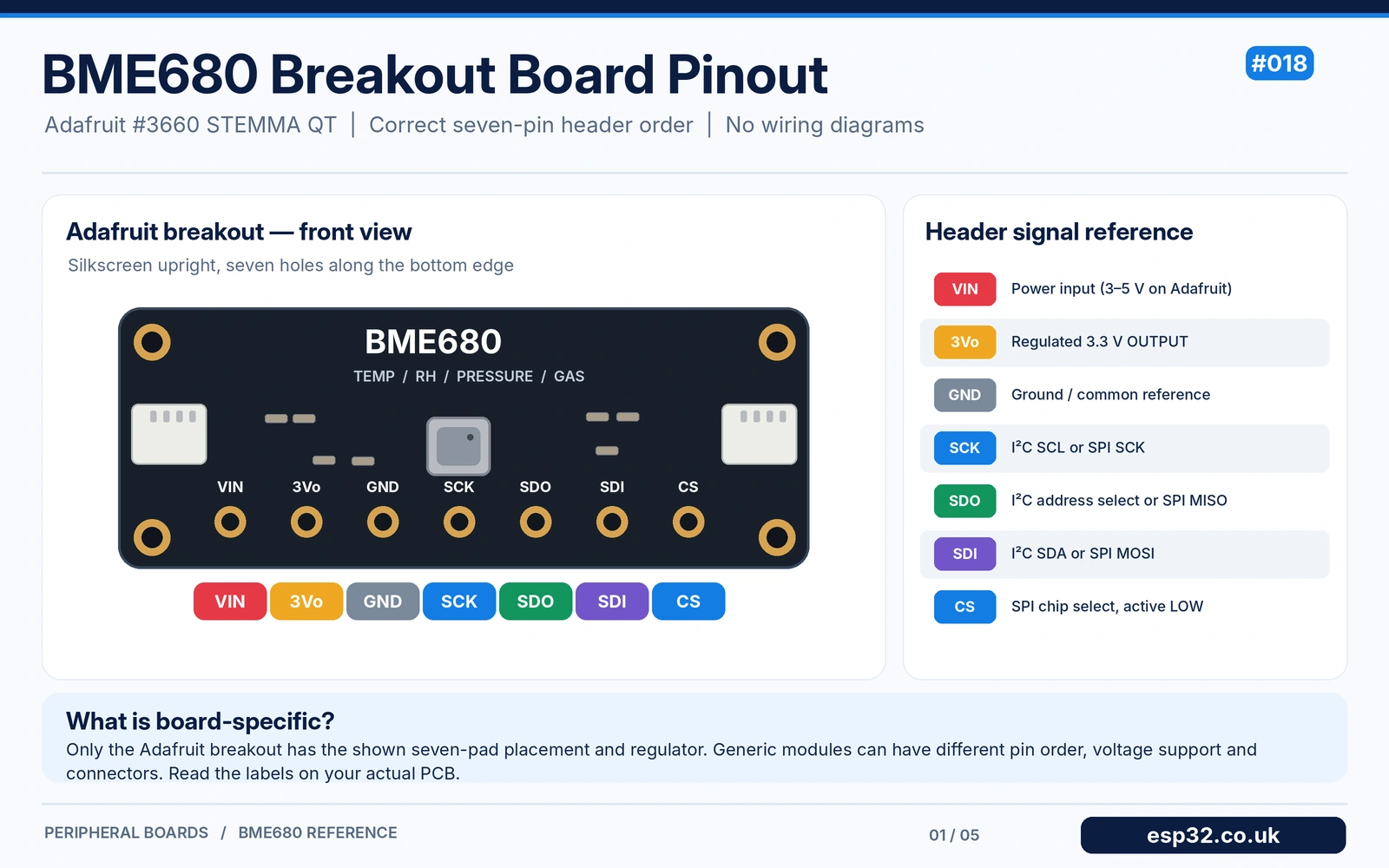
BME680 breakout pinout: Adafruit #3660
Adafruit sells both an earlier header-only BME680 breakout and a later STEMMA QT / Qwiic-compatible version. The standard front header remains seven signals, clearly printed beside the holes. On the manufacturer’s top-view photograph, the header reads VIN, 3Vo, GND, SCK, SDO, SDI, CS from left to right. No eighth pin should be invented to fill a graphic.
| Header label | Function | Use with an ESP32 |
|---|---|---|
| VIN | Breakout-board power input; Adafruit includes a regulator and level shifting. | Power from ESP32 3V3 for a 3.3 V I²C design. |
| 3Vo | 3.3 V regulator output on the Adafruit breakout. | Normally leave unconnected; do not treat as VIN. |
| GND | Common electrical reference. | ESP32 GND. |
| SCK | I²C clock SCL or SPI clock SCK. | GPIO22 for example I²C; GPIO18 for example SPI. |
| SDO | SPI MISO, or I²C address-select input. | Factory state uses 0x77; grounding the signal selects 0x76 for I²C. |
| SDI | I²C data SDA or SPI MOSI. | GPIO21 for I²C; GPIO23 for SPI. |
| CS | SPI chip select; idle-high for I²C mode on the breakout. | Leave at its verified factory I²C configuration; connect to GPIO5 for SPI. |
The breakout’s 3.3 V regulator output is often printed 3Vo, not 3V3. Supplying the board via VIN while also driving the 3Vo rail externally can bypass or back-feed its regulator; unless your exact board documentation permits it, use VIN and leave 3Vo disconnected. The raw BME680 chip is not 5 V tolerant: Bosch specifies VDD 1.71–3.6 V and VDDIO 1.2–3.6 V. Only boards with known regulators and logic translation can accept 5 V on their labelled VIN.
Generic BME680 module differences
Low-cost sensor boards may have four pins (VCC, GND, SCL, SDA), six pins (VCC, GND, SCL/SCK, SDA/SDI, SDO, CSB), or another manufacturer-specific arrangement. Some boards omit a regulator and expect only 3.3 V; others explicitly support 3.3–5 V inputs. A generic PCB labelled VCC is not automatically equivalent to Adafruit VIN. Even where pin names match, their physical order can change. Read the PCB silkscreen, the seller’s schematic if genuine, and the regulator part marking before connecting it to an ESP32.
For the dedicated home-automation configuration, see our BME680 ESPHome and indoor air monitoring guide. This article instead covers the breakout board itself and Arduino-level operation.
I²C address selection: 0x77 or 0x76
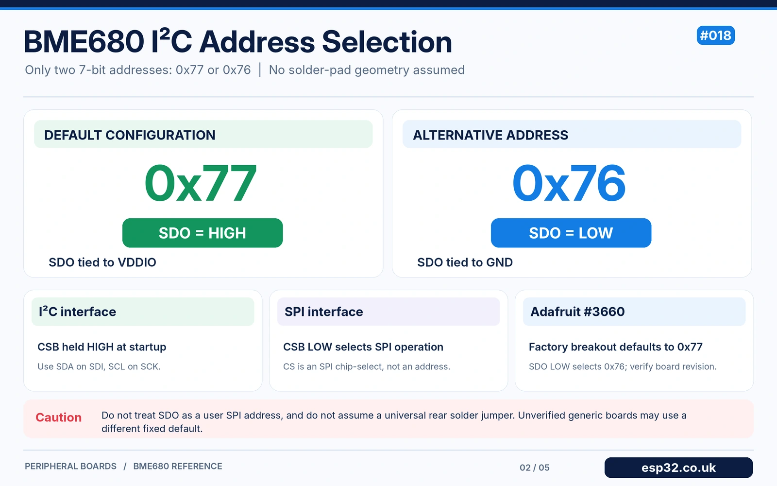
The BME680 chip offers exactly two 7-bit I²C addresses. The physical SDO signal selects the address when the device is in I²C mode. On Adafruit #3660, the normal configuration is 0x77, and grounding SDO selects 0x76. This is not a multi-bit address system like PCA9685Price or PCF8574Price. Some generic modules are strapped to 0x76 at manufacture, so always run an I²C scanner before assuming your board’s default.
| SDO / address level | BME680 7-bit I²C address | Arduino begin call |
|---|---|---|
| HIGH (to VDDIO on raw chip; Adafruit default) | 0x77 | bme.begin(0x77) |
| LOW (to GND) | 0x76 | bme.begin(0x76) |
The raw chip’s CSB pin must be HIGH for I²C. On the Adafruit breakout, the normal I²C configuration is already provided, so the only normal user connections are power, ground, SCK and SDI. Do not solder a random pair of pads on a different board: verify that the pad actually connects the SDO/address signal to ground. Not every BME680 board exposes an address solder bridge.
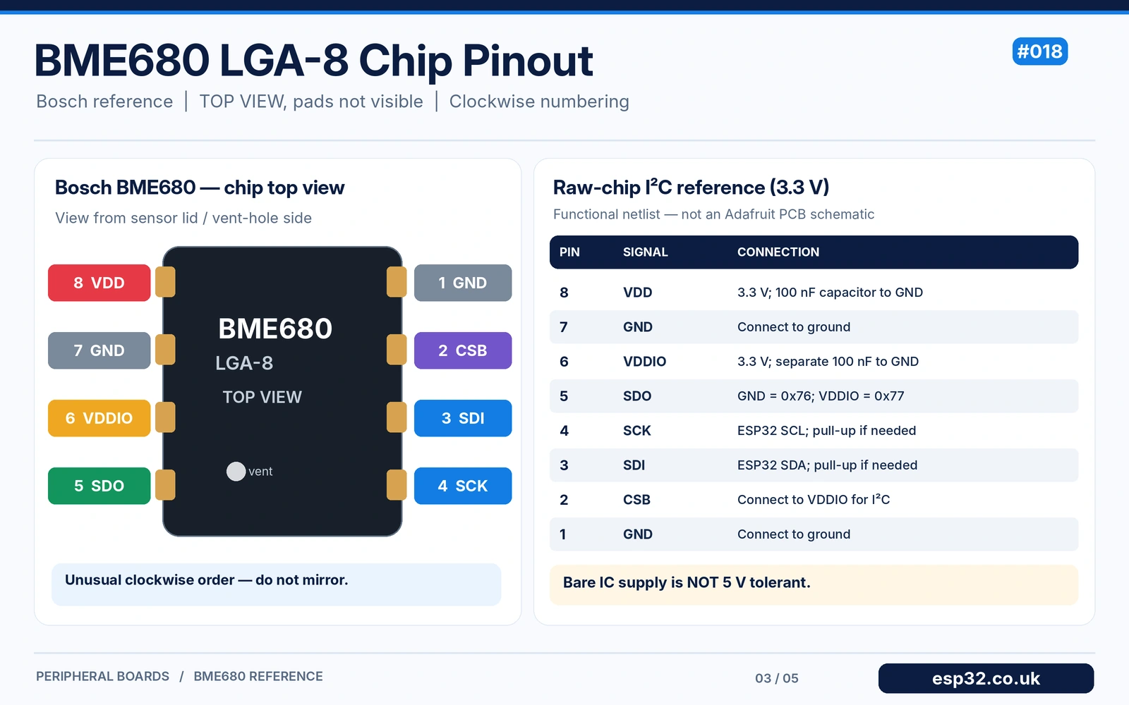
Bosch BME680 chip pinout: the actual eight pads
The Bosch LGA-8 sensor package is not a seven-pin breakout board. It has a distinct physical orientation, and a raw-chip reference must use the TOP VIEW defined in Bosch datasheet section 7.1, not a mirrored underside drawing. Bosch notes that the top-view numbering runs clockwise, unusually for this package. The pin-1 side is the right column in the official top-view illustration, while pin 8 is at the top left.
| Pad number | Bosch signal | Purpose |
|---|---|---|
| 1 | GND | Ground; connect with pad 7. |
| 2 | CSB | SPI chip select; connect to VDDIO for I²C. |
| 3 | SDI | I²C data (SDA) / SPI MOSI. |
| 4 | SCK | I²C clock (SCL) / SPI SCK. |
| 5 | SDO | I²C address selection / SPI MISO. |
| 6 | VDDIO | Digital input/output supply, 1.2–3.6 V. |
| 7 | GND | Second ground pad. |
| 8 | VDD | Main sensor supply, 1.71–3.6 V. |
On the chip top view, the left column from top down is 8 VDD, 7 GND, 6 VDDIO, 5 SDO; the right column from top down is 1 GND, 2 CSB, 3 SDI, 4 SCK. The exact Bosch diagram should be the reference for any footprint or PCB manufacturing work; an article illustration is only a readable pin-position guide.
Functional circuit: parts and electrical nets, without drawn wires
For the standalone 3.3 V raw IC, both VDD and VDDIO can be supplied from a suitably clean 3.3 V rail. Bosch’s reference I²C circuit places a 100 nF ceramic capacitor from each supply to GND near the chip, connects both GND pads, ties CSB to VDDIO, and chooses SDO HIGH or LOW for the address. SDA/SCL are open-drain bus signals and require adequate pull-ups to the bus logic supply, commonly 4.7 kΩ each when the bus does not already contain pull-ups.
| Connection group | Required chip pins / components | Purpose |
|---|---|---|
| Main supply | VDD (pad 8) → 3.3 V; 100 nF to GND | Stable sensor power. |
| I/O supply | VDDIO (pad 6) → 3.3 V; 100 nF to GND | 3.3 V digital interface. |
| Ground | Both GND pads 1 and 7 → GND | Common reference. |
| I²C mode | CSB (pad 2) → VDDIO | Select I²C protocol. |
| I²C data | SDI (pad 3) → SDA bus, pull-up to VDDIO | Open-drain data channel. |
| I²C clock | SCK (pad 4) → SCL bus, pull-up to VDDIO | Open-drain clock channel. |
| Address | SDO (pad 5) → GND (0x76) or VDDIO (0x77) | Address strap, never floating on a raw design. |
This is a chip-level electrical net reference, not a reproduction of the Adafruit PCB schematic or every GY-series board. Regulator, level-shifter, STEMMA QT, and pull-up circuitry are already present on some breakouts and must not be blindly duplicated. In this cluster we deliberately avoid AI-drawn wiring lines: component netlists and pin-to-pin tables convey the connections with less risk of fake or shorted wires.
ESP32 to BME680 connection table: I²C mode
For a standard ESP32-WROOM DevKit, a four-wire I²C connection is easiest. GPIO21 and GPIO22 are widely used Arduino choices; on another ESP32 variant, select board-appropriate I²C pins and change Wire.begin(). The table below assumes the Adafruit #3660 breakout, not a raw 8-pad sensor.
| ESP32-WROOM DevKit pin | Adafruit BME680 pin | Electrical purpose |
|---|---|---|
| 3V3 | VIN | Power breakout at the MCU’s 3.3 V logic level. |
| GND | GND | Shared ground. |
| GPIO21 / SDA | SDI | I²C data. |
| GPIO22 / SCL | SCK | I²C clock. |
| Not connected | 3Vo | Regulator output; leave open in this example. |
| Not connected for default configuration | SDO | Factory default I²C 0x77; ground only if selecting 0x76. |
| Not connected for default configuration | CS | Breakout keeps proper I²C configuration; verify generic designs separately. |
If your BME680 does not respond, scan the I²C bus for 0x76 and 0x77. An address response alone does not confirm the chip is genuine, because other Bosch sensors may share the same address; the BME680 family uses chip-ID register 0xD0 with value 0x61. A BME280 uses 0x60 and a BMP280 typically uses 0x58.
ESP32 to BME680 connection table: four-wire SPI mode
SPI is useful if your I²C bus is already crowded or you require chip-select isolation. The following is a typical classic ESP32-WROOM pin selection using the Adafruit BME680 breakout, which accepts SPI logic at its VIN level. The BME680 does not have an I²C address while using SPI: its CS pin selects the device instead.
| ESP32-WROOM DevKit pin | Adafruit BME680 pin | SPI signal |
|---|---|---|
| 3V3 | VIN | Breakout power input. |
| GND | GND | Shared ground. |
| GPIO18 / SCK | SCK | SPI clock. |
| GPIO23 / MOSI | SDI | Controller out, sensor in. |
| GPIO19 / MISO | SDO | Sensor out, controller in. |
| GPIO5 / CS | CS | Active-low chip select. |
| Not connected | 3Vo | Regulator output; do not drive. |
The Adafruit Arduino library supports a hardware-SPI constructor. Initialise SPI.begin(18, 19, 23, 5) before begin(), and construct the sensor with Adafruit_BME680 bme(5, &SPI);. For this guide the full working example below uses I²C to minimise wiring and library configuration.

Arduino IDE: Adafruit BME680 library example
Install Adafruit BME680 Library through Arduino IDE Library Manager. Install its prompted dependencies, including Adafruit Unified Sensor and Adafruit BusIO when required. The library exposes begin(), setGasHeater(), setTemperatureOversampling(), and performReading(). The code below is original but follows the published official API. It has not been bench-tested on your particular breakout.
#include <Arduino.h>
#include <Wire.h>
#include <Adafruit_BME680.h>

constexpr int I2C_SDA = 21;     // Classic ESP32-WROOM DevKit
constexpr int I2C_SCL = 22;
constexpr uint8_t BME_ADDR = 0x77;  // Change to 0x76 if SDO is LOW

Adafruit_BME680 bme(&Wire);

void setup() {
  Serial.begin(115200);
  delay(500);
  Wire.begin(I2C_SDA, I2C_SCL);
  Wire.setClock(100000);

  if (!bme.begin(BME_ADDR)) {
    Serial.println("BME680 not detected at selected address.");
    Serial.println("Check 3.3V, GND, SDA, SCL and 0x76/0x77.");
    while (true) delay(1000);
  }

  bme.setTemperatureOversampling(BME680_OS_8X);
  bme.setHumidityOversampling(BME680_OS_2X);
  bme.setPressureOversampling(BME680_OS_4X);
  bme.setIIRFilterSize(BME680_FILTER_SIZE_3);
  bme.setGasHeater(320, 150); // 320 degrees C, 150 ms

  Serial.println("BME680 ready. Gas resistance needs warm-up.");
}

void loop() {
  if (!bme.performReading()) {
    Serial.println("BME680 reading failed");
    delay(1500);
    return;
  }

  Serial.printf("Temperature: %.2f C\n", bme.temperature);
  Serial.printf("Humidity: %.2f %% RH\n", bme.humidity);
  Serial.printf("Pressure: %.2f hPa\n", bme.pressure / 100.0f);
  Serial.printf("Gas resistance: %.1f kOhm (raw)\n",
                bme.gas_resistance / 1000.0f);
  Serial.println("---");
  delay(2000);
}
A serial monitor at 115200 baud will show temperature, humidity, pressure and gas resistance. Raw gas numbers vary substantially between devices and change after the heater has warmed up. Do not copy a sample gas reading and present it as an expected indoor air-quality target, and do not infer safe/unsafe air from one resistance threshold.
Gas heater, measurement timing and stabilisation
The internal gas heater warms the metal-oxide sensing element to a configured temperature before measuring its electrical resistance. In the sample sketch, setGasHeater(320, 150) configures a 320 °C heater target for 150 ms. This is a sensor-internal heater; the whole breakout board and ambient air do not reach 320 °C. The device combines the heater phase with temperature, pressure and humidity conversion according to the selected operating mode.
Bosch describes a staged acquisition process and gas-valid/heater-stable status flags. The Adafruit library performs the usual compensation and sequencing. To obtain stable comparisons, allow an initial conditioning period and a repeatable warm-up procedure. Adafruit recommends an initial 48-hour conditioning and about 30 minutes of operation in the selected measurement mode when making comparative VOC trend measurements; these are useful starting practices, not a guarantee of laboratory-grade air quality calibration.
| Influence | Why it changes the result | Practical response |
|---|---|---|
| Heater setting | Heater target and dwell time affect MOX sensitivity. | Use consistent settings between comparisons. |
| Warm-up and early use | Baseline can drift while the element stabilises. | Allow repeatable warm-up; log trend over time. |
| Ambient humidity | Water vapour changes sensor response. | Record RH alongside gas resistance. |
| PCB/enclosure heat | Nearby components and enclosure conditions bias ambient readings. | Keep airflow around the sensor and separate from hot components. |
| VOC mixtures | MOX sensor responds to mixtures, not one uniquely identified gas. | Describe results as general VOC-related response, not chemical analysis. |
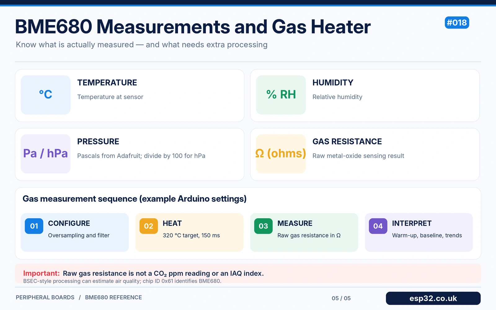
BME680 gas resistance versus an IAQ score
The Adafruit Arduino library gives you a usable gas resistance in ohms. That is not the same as an Indoor Air Quality index, VOC concentration in parts per million, or a measured CO₂ value. Bosch’s BSEC algorithms can combine temperature, humidity, gas resistance, time, baselines and sensor-specific processing to provide additional air-quality metrics, but their supported platforms, licensing and configuration should be checked separately. Treat values from different algorithms or modules as not directly comparable.
For dashboards and home automations, interpret the sensor as a trend device unless you have established appropriate baselines and validated your setup. A household CO₂ sensor based on NDIR or photoacoustic sensing is a different instrument. For that distinction, see the existing SCD40 versus SCD41 CO₂ sensor comparison.
Power consumption and enclosure design
The BME680 can operate with low average current when measuring only temperature, humidity and pressure, but gas measurement activates a heater and increases instantaneous current. Bosch lists substantially different consumption for different duty cycles. A battery device should measure actual module current, particularly if its breakout contains an LED or regulator with standby draw. During enclosure design, protect the sensor opening from condensation, dust and direct splashes, and avoid placing it directly above the ESP32 regulator, Wi-Fi module or another heat source.
Troubleshooting: BME680 not found or readings look wrong
| Symptom | Likely cause and solution |
|---|---|
| I²C scanner sees neither 0x76 nor 0x77 | Confirm board supply and logic levels, shared ground, and SDA/SDI versus SCL/SCK names. Check actual ESP32 GPIO pins. |
| I²C scanner sees 0x76 but begin(0x77) fails | Change BME_ADDR to 0x76; inspect board address configuration. |
| I²C device ACKs but BME680 library rejects it | Another sensor may share the address; BME680 chip ID is 0x61 in register 0xD0. |
| Temperature reads too high | Possible self-heating, ESP32/regulator heat or enclosed airflow; relocate the breakout. |
| Gas resistance changes a lot after startup | Normal heater warm-up/conditioning, humidity or VOC changes; wait and compare trends. |
| No gas reading or zero | Check heater configuration, selected library/version, reading completion and sensor validity. |
| Library reports pressure in unexpected units | Adafruit bme.pressure is in Pa; divide by 100 for hPa. |
| ESP32 works on I²C but not SPI | Check SDI=MOSI, SDO=MISO, CS=GPIO5, SCK=GPIO18, and hardware SPI constructor. |
| Breakout gets warm or fails at 5 V | A generic raw-chip board may lack regulator/level shifting; use 3.3 V unless proven otherwise. |
BME680 compared with BME280 and BME688
Choose BME280 when you need only temperature, humidity and pressure with no heater-based gas measurements. BME680 adds the MOX element and heater, making it attractive for air-quality trends, but brings warm-up and interpretation issues. The newer BME688 family extends related gas-sensing applications and software support; compatibility and operating modes depend on the exact hardware and library, so do not assume that a BME688 board is an identical drop-in replacement for every BME680 application.
Related guides on esp32.co.uk/ include BME280 breakout pinout and address selection, BME280 vs BME680 vs BME688, and BME680 ESPHome and indoor air monitoring.
Frequently asked questions
Does the BME680 measure CO₂?
No. It measures temperature, humidity, pressure and a heated MOX gas resistance. Some software libraries calculate an estimated CO₂-equivalent or air-quality score from sensor trends, but that is not a direct carbon-dioxide measurement. Use an appropriate CO₂ sensor when ppm accuracy matters.
Is the Adafruit BME680 default address 0x76 or 0x77?
It is 0x77 in the documented Adafruit factory configuration. Connecting SDO to ground selects 0x76. Generic boards can be strapped differently; check the actual module before configuring the software.
Can two BME680s share one ESP32?
Yes, using distinct I²C addresses 0x76 and 0x77, separate I²C buses, or an I²C multiplexer when addresses collide. Over SPI, give each device a different CS line. The TCA9548A multiplexer guide explains an alternative for identical-address devices.
Is 5 V safe for every BME680 breakout?
No. The Adafruit #3660 VIN input includes a regulator and level shifting, but the Bosch raw sensor is only designed for low-voltage supplies. Generic modules are not interchangeable. Confirm the exact board’s regulator and logic-level design before using 5 V.
How should I interpret a gas resistance value?
Keep a historical baseline, use consistent heater settings, consider humidity and temperature, and look for sustained changes rather than treating one kΩ reading as a universal VOC or IAQ threshold. An absolute concentration claim requires a separately validated method.
Technical references
- Adafruit BME680 breakout pinouts — #3660 labelled header and 3Vo regulator output.
- Adafruit Arduino BME680 guide — I²C address, Arduino library and sensor warm-up.
- Bosch BME680 Datasheet BST-BME680-DS001-09 (2024) — eight-pad top view, supplies, I²C and SPI nets, heaters and gas readings.
- Adafruit BME680 Arduino library — maintained public API and example code.
- Bosch explanation of BME680 data interpretation — raw gas resistance versus processed air-quality metrics.
Accuracy note: All circuit information in this esp32.co.uk/ guide is linked to a specified sensor or breakout revision. No AI-drawn wires or unverified PCB traces are included. Readers should consult their own module’s silkscreen and manufacturer datasheet before applying power. Code follows the published Adafruit library API but has not been tested on the reader’s specific hardware.