
The MPU6050 is a six-axis inertial measurement unit (IMU): a three-axis accelerometer and a three-axis gyroscope with an internal temperature sensorPrice. The inexpensive GY-521 is one of the most common breakout boards, while Adafruit sells a different MPU6050 board with STEMMA QT connectors and a rear I²C-address solderPriceAliExpress price bridge. This esp32.co.uk/ hardware reference explains both versions without mixing up their headers, regulators or solder pads. It covers the board pinout, 0x68/0x69 addresses, optional interrupt pin, ESP32 connection tables, sensor ranges and working Arduino code using the Adafruit MPU6050 library.
Quick setup for a classic ESP32-WROOM DevKit: connect your verified 3.3 V-compatible MPU6050 breakout power input to 3V3, ground to GND, SDA to GPIO21, and SCL to GPIO22. Leave INT disconnected for the basic Arduino sketch. The default 7-bit I²C address is 0x68. High on AD0 selects 0x69. The exact power-input requirement depends on your board’s regulator and level shifterPriceAliExpress price, so identify the breakout revision first.
Do not use a generated wiring picture as electrical evidence. This reference deliberately uses labelled pinout diagrams, readable pin-to-pin tables and functional blocks with no drawn jumper wiresAliExpress price. The chip itself is a low-voltage device; a board labelled “5V VCC” is not proof that its SDA/SCL are 5 V tolerant.
What the MPU6050 measures
| Function | What you get | Common use |
|---|---|---|
| 3-axis accelerometer | X/Y/Z acceleration, including gravity, in m/s² through Adafruit Unified Sensor | Tilt, vibration, linear movement with careful processing |
| 3-axis gyroscope | X/Y/Z angular velocity, in rad/s through Adafruit Unified Sensor | Rotation rates and orientation integration |
| Temperature sensor | Internal chip temperature, °C | Chip-temperature monitoring, not a calibrated ambient thermometer |
| I²C interface | Standard two-wire interface, two possible 7-bit addresses | ESP32, Arduino, STM32 and Raspberry Pi projects |
| INT output | Configurable interrupt signaling from the chip | Data-ready or configured motion events |
| Auxiliary bus | Separate auxiliary I²C pins used for external sensors | Advanced sensor configurations; not needed for a basic IMU read |
| Digital Motion Processor | Built-in motion-processing hardware | Advanced use with suitable firmware and supporting library; not enabled by the basic sketch |
The MPU6050 is a 6-DoF device, not a 9-DoF compass sensor. It has no magnetometer and cannot measure an absolute compass heading by itself. Accelerometer-only tilt is sensitive to movement, and integrating a gyro rate creates drift over time. “Pitch and roll” examples require signal processing; yaw cannot remain absolutely referenced without an external heading reference or another method.
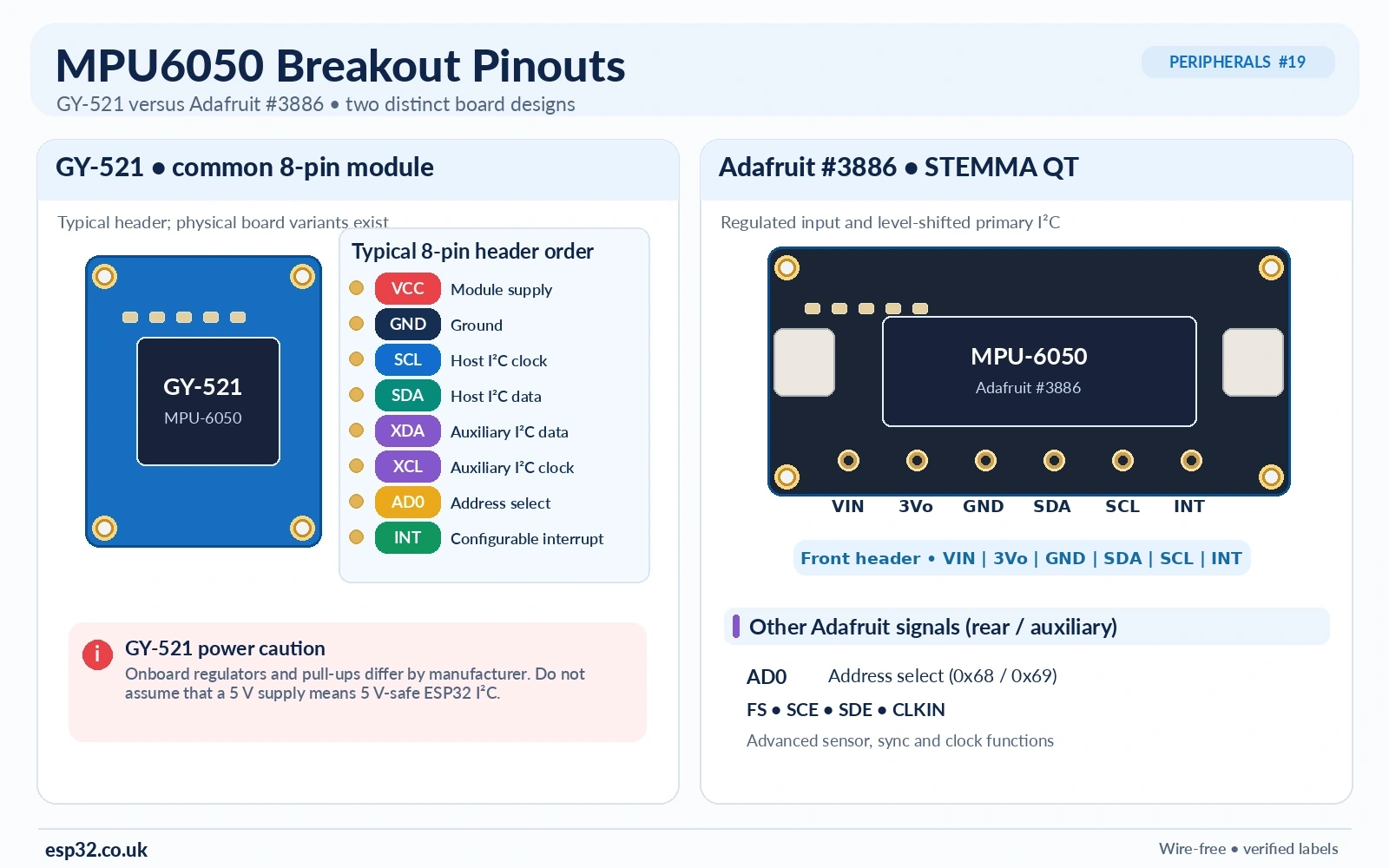
GY-521 MPU6050 breakout pinout: all eight pins
The familiar small blue GY-521 commonly has an eight-position header labelled VCC, GND, SCL, SDA, XDA, XCL, AD0, INT in that sequence. Some boards reverse the physical orientation or use ADO instead of AD0, so read the silkscreen while holding the actual board in front of you. XDA/XCL are not extra ESP32 I²C connections for normal measurements.
| GY-521 label | Purpose | What to do in a basic ESP32 project |
|---|---|---|
| VCC | Breakout power input; commonly routed through an LDO | Use only a verified compatible supply; see regulator caution below |
| GND | Ground reference | ESP32 GND |
| SCL | Main I²C clock | ESP32 GPIO22 (classic DevKit example) |
| SDA | Main I²C data | ESP32 GPIO21 (classic DevKit example) |
| XDA | Auxiliary I²C data for external sensors | Leave unconnected |
| XCL | Auxiliary I²C clock for external sensors | Leave unconnected |
| AD0 / ADO | I²C address selection bit | Low: 0x68; high: 0x69 using chip logic voltage |
| INT | Programmable interrupt output | Optional; leave disconnected for basic readings |
Common GY-521 modules include an onboard voltage regulator, but their I²C pull-up arrangement varies. A regulator does not by itself provide level shifting, and not all modules behave correctly with 3.3 V applied to VCC because some regulators need additional headroom. On a real GY-521, inspect the regulator and pull-up connections, and verify the sensor’s VDD under load. If the board is specified for 5 V VCC, confirm that SDA/SCL still rise only to 3.3 V before connecting to an ESP32; otherwise use a correctly designed level shifter or a known 3.3 V breakout.
Adafruit MPU6050 breakout: not the same as a GY-521
Adafruit’s MPU6050 breakout adds a power regulator, I²C level shifting and STEMMA QT connectors. Its published named signals include VIN, 3Vo, GND, SDA, SCL, INT, AD0, FS, SCE, SDE and CLKIN. The advanced pins are intended for special-purpose synchronization, auxiliary sensor functions or external clocking; they are not necessary for the basic example.
| Adafruit breakout signal | Description |
|---|---|
| VIN | Regulated breakout power input; accepts 3–5 V according to Adafruit |
| 3Vo | Output from the onboard 3.3 V regulator, not the preferred supply input |
| GND | Ground |
| SDA / SCL | Level-shifted I²C data and clock, with onboard 10 kΩ pull-ups |
| INT | Sensor interrupt output; mode and polarity depend on registers |
| AD0 | Address selection; high or rear jumper bridged gives 0x69 |
| FS | External frame synchronization; advanced |
| SCE / SDE | Auxiliary sensor bus / interface pins; advanced |
| CLKIN | External reference clock input; advanced |
For a classic 3.3 V ESP32, powering this exact Adafruit board from 3V3 → VIN keeps its I²C interface within the ESP32 voltage domain. Adafruit’s regulator is not interchangeable with the raw MPU6050 power pins. For pin locations and the rear bridge, follow the official Adafruit board documentation and your board’s silkscreen rather than a generic GY-521 illustration.
I²C addresses 0x68 and 0x69: AD0 pin versus solder bridge
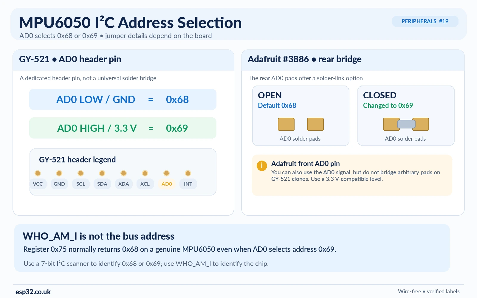
The MPU6050 uses one hardware address-select bit. AD0 low = 0x68; AD0 high = 0x69. A typical GY-521 exposes an AD0 header pin, often with a default pull-down. The Adafruit breakout also has a rear address solder jumper: bridging it pulls AD0 high and changes the address. Do not describe every generic GY-521 as having that same rear jumper.
| Module/configuration | AD0 state | 7-bit I²C address |
|---|---|---|
| GY-521 default (typical) | LOW | 0x68 |
| GY-521 AD0 tied to valid chip logic high | HIGH | 0x69 |
| Adafruit breakout address jumper open | LOW | 0x68 |
| Adafruit breakout address jumper solder-bridged | HIGH | 0x69 |
Use 0x68 or 0x69 in mpu.begin(address) or Wire.beginTransmission(address). Do not accidentally use the eight-bit read/write addresses from low-level documentation. Also do not confuse the I²C bus address with the WHO_AM_I device-identification register: the latter lives at register 0x75 and normally reads 0x68 even when AD0 makes the device respond at 0x69. The register deliberately omits the selectable address bit.
You can put two MPU6050 sensors on one ESP32 I²C bus when one is at 0x68 and the other at 0x69. For three or more with the same fixed address, use a second I²C controller where supported or an I²C multiplexer such as the TCA9548A.
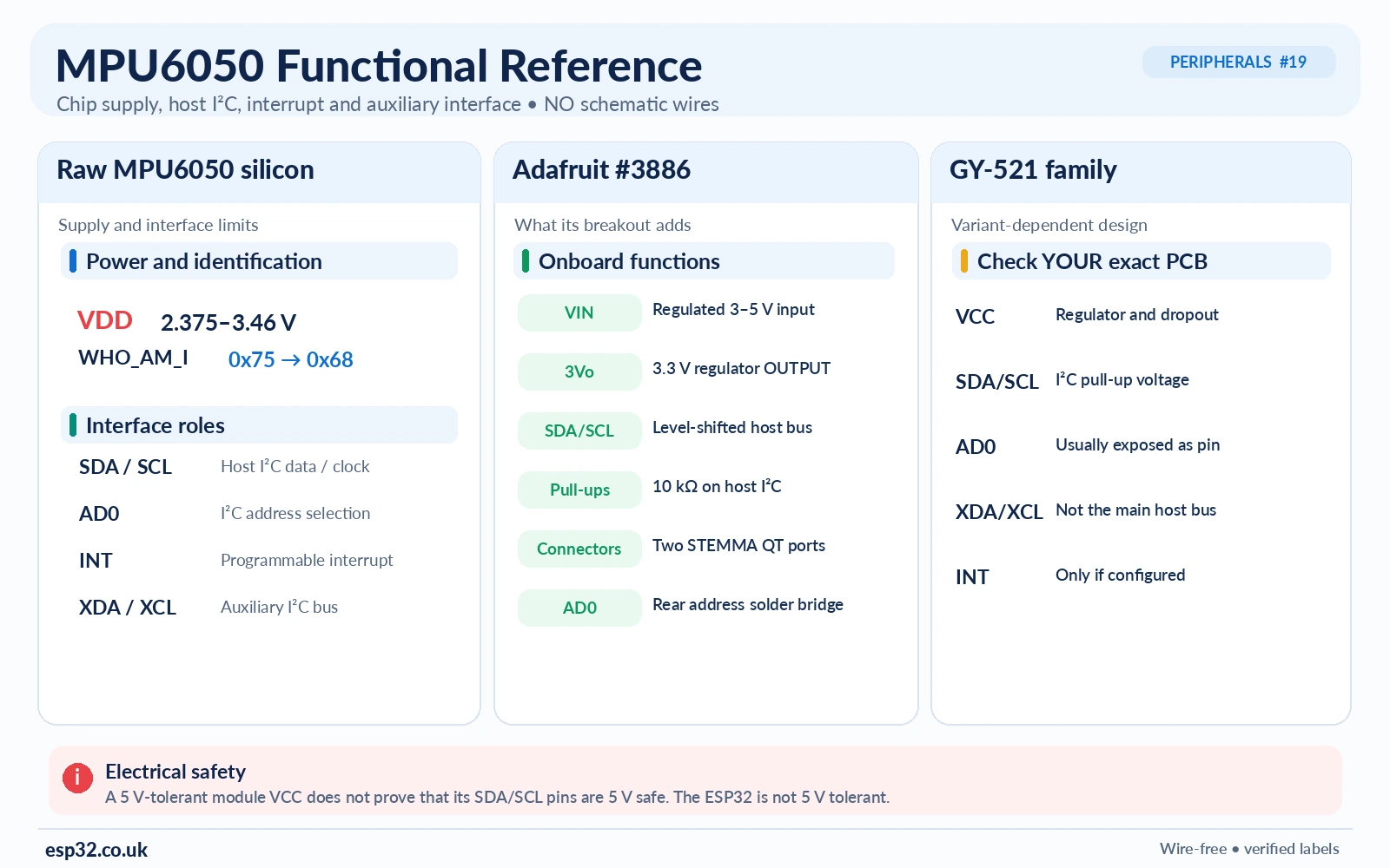
Functional electrical reference: what must be powered and connected
At the raw MPU6050 chip level, the supply domain operates at low voltage (the original TDK/InvenSense specification lists VDD = 2.375–3.46 V). The auxiliary VLOGIC supply is also not a 5 V input. The chip requires appropriate local decoupling, a valid power-up sequence, and I²C lines pulled to the correct logic supply. The exact capacitor values and pin connections belong to the original chip reference circuit; they must not be guessed from a breakout-board photograph.
On a breakout, the input labelled VCC or VIN can lead through a regulator or through an entirely different arrangement. A board may have a power LED, protection components, and I²C pull-ups. These are board features, not guarantees for every board called “MPU6050”. For technical accuracy this article provides a functional block and net-reference table rather than a fabricated representation of the GY-521 PCB traces.
| Electrical net | Verified requirement |
|---|---|
| Raw chip VDD | Use the low-voltage range specified by the TDK MPU6050 product specification |
| Chip logic supply | Match the permitted VLOGIC and bus-level requirements |
| SDA / SCL pull-ups | Pull up to the actual logic rail; check any resistors already on the breakout |
| Ground | Common reference between sensor and controller |
| Bypass capacitors | Close to the chip power pins as shown in its application circuit |
| AD0 | A defined LOW or valid HIGH for address selection |
| INT | Optional host input when configured; not required for polling |
| XDA / XCL | Optional auxiliary I²C interface, not a substitute for host SDA/SCL |
ESP32 to MPU6050 connection tables (I²C)
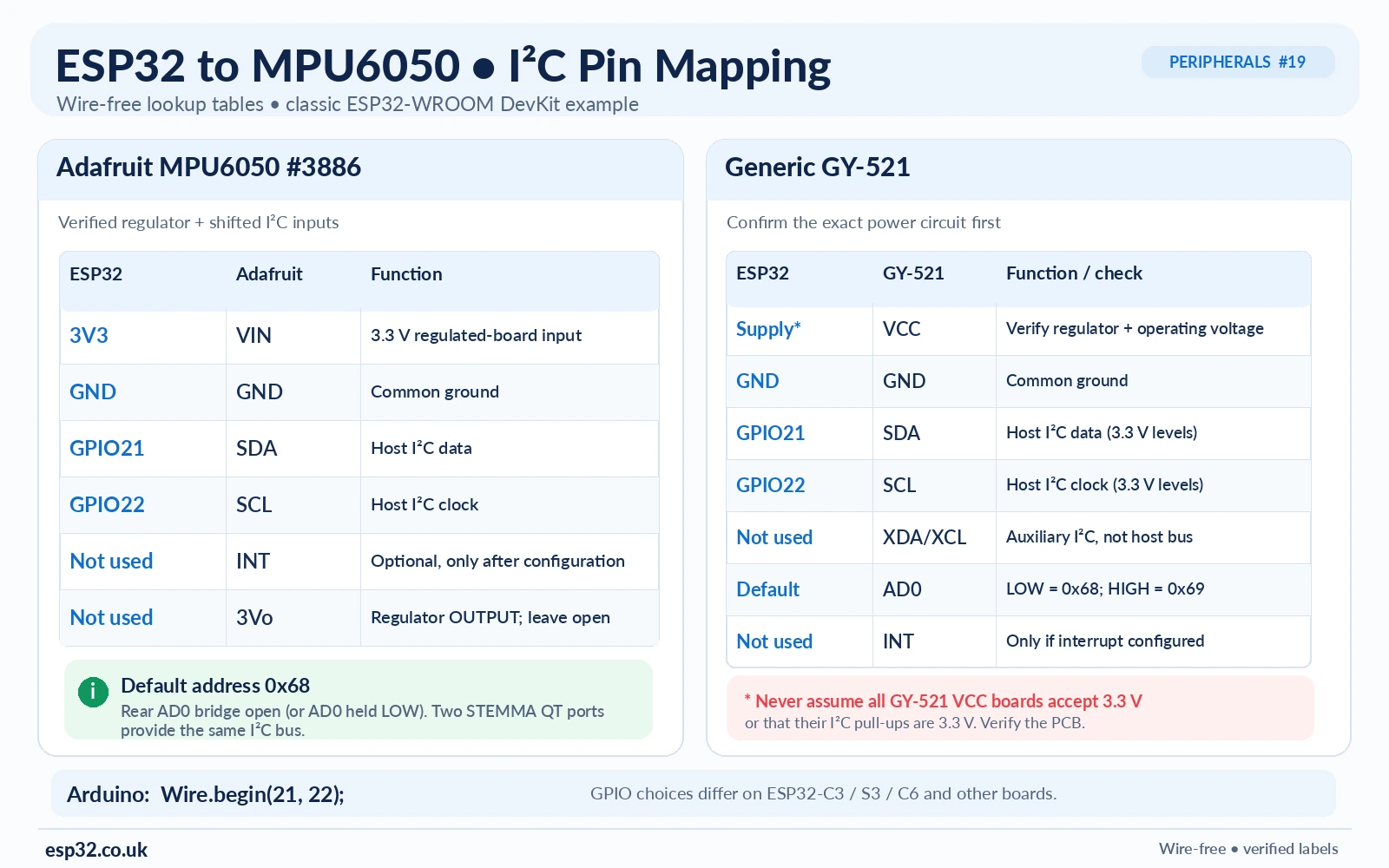
The following is for a classic ESP32-WROOM DevKit. Other ESP32 families—C3, C6, S3, P4 and others—can expose different I²C-capable pins. The firmware explicitly selects GPIO21/GPIO22 with Wire.begin(21, 22).
| Classic ESP32 DevKit | Adafruit MPU6050 breakout | Function |
|---|---|---|
| 3V3 | VIN | Supply this specific breakout at 3.3 V |
| GND | GND | Common ground |
| GPIO21 | SDA | I²C data |
| GPIO22 | SCL | I²C clock |
| Not connected | INT | Not needed for basic polling |
| Not connected | AD0 | Use default 0x68, unless you select 0x69 with the address jumper |
| Not connected | 3Vo | Regulator output; do not connect to ESP32 3V3 output |
| Classic ESP32 DevKit | Generic GY-521 header | Extra verification |
|---|---|---|
| 3V3 or documented VCC source | VCC | Use the supply that actually yields a valid sensor VDD and 3.3 V-safe SDA/SCL; verify board LDO |
| GND | GND | Shared ground |
| GPIO21 | SDA | Bus pull-ups must not rise above ESP32-safe logic levels |
| GPIO22 | SCL | Do not swap main and auxiliary clock pins |
| Not connected | XDA / XCL | Auxiliary interface unused |
| Not connected | AD0 | Typical default address 0x68 |
| Not connected | INT | Optional, add only when configuring interrupts |
With either board, if the I²C scan detects neither 0x68 nor 0x69, measure the supply, inspect the board’s logic voltage, verify SDA/SCL and address selection, and use the ESP32 I²C scanner reference. A sensor that responds but emits nonsense readings may be underpowered or affected by bus pull-ups or clone-chip differences.
Install the Arduino library and run a first ESP32 sketch
Install the maintained Adafruit MPU6050 library using Arduino IDE Library Manager, plus the required Adafruit BusIO and Adafruit Unified Sensor dependencies if prompted. The published API exposes mpu.begin(address), setAccelerometerRange(), setGyroRange(), setFilterBandwidth() and getEvent(). The following is a small original example using those supported calls, not a pasted copy of the library example. It does not require the INT or auxiliary pins.
#include <Arduino.h>
#include <Wire.h>
#include <Adafruit_MPU6050.h>
#include <Adafruit_Sensor.h>

constexpr int I2C_SDA = 21;    // Classic ESP32 DevKit
constexpr int I2C_SCL = 22;
constexpr uint8_t MPU_ADDR = 0x68; // Change to 0x69 if AD0 is HIGH

Adafruit_MPU6050 imu;

void setup() {
  Serial.begin(115200);
  delay(500);
  Wire.begin(I2C_SDA, I2C_SCL);
  Wire.setClock(100000); // Start conservatively at 100 kHz

  if (!imu.begin(MPU_ADDR, &Wire)) {
    Serial.println("MPU6050 not found. Check I2C, power, and AD0.");
    while (true) delay(1000);
  }

  imu.setAccelerometerRange(MPU6050_RANGE_2_G);
  imu.setGyroRange(MPU6050_RANGE_250_DEG);
  imu.setFilterBandwidth(MPU6050_BAND_21_HZ);
  Serial.println("MPU6050 ready: accel m/s^2, gyro rad/s");
}

void loop() {
  sensors_event_t acc, gyro, temp;
  if (!imu.getEvent(&acc, &gyro, &temp)) {
    Serial.println("Measurement read failed");
    delay(300);
    return;
  }

  Serial.printf("a [m/s^2] x=%.2f y=%.2f z=%.2f | ",
                acc.acceleration.x,
                acc.acceleration.y,
                acc.acceleration.z);
  Serial.printf("g [rad/s] x=%.3f y=%.3f z=%.3f | T=%.1f C\n",
                gyro.gyro.x, gyro.gyro.y, gyro.gyro.z,
                temp.temperature);
  delay(400);
}
Open Serial Monitor at 115200. With the sensor stationary and roughly level, the acceleration vector magnitude is near the local acceleration of gravity (~9.81 m/s²), although individual signs and axis readings depend on the PCB orientation and sensor mounting. Gyroscope readings should be near zero when stationary, with noise and bias. Rotate the board gently and check that the appropriate gyro axis responds. The temperature is the sensor die reading, not a certified ambient-air measurement.
What do the serial values mean?
MPU6050 ready: accel m/s^2, gyro rad/s
a [m/s^2] x=0.05 y=-0.12 z=9.78 | g [rad/s] x=0.004 y=-0.002 z=0.006 | T=28.4 C
The line above is illustrative, not a bench measurement. When comparing against data sheets and other libraries, note the Adafruit Unified Sensor units: acceleration in m/s² and angular rate in rad/s. Many MPU6050 examples instead display accelerometer g units and gyro degrees per second. Convert deliberately: 1 g ≈ 9.80665 m/s² and degrees/s = radians/s × 180/π.
Accelerometer ranges, gyroscope ranges and filter settings
| Channel | Selectable full-scale range | Trade-off |
|---|---|---|
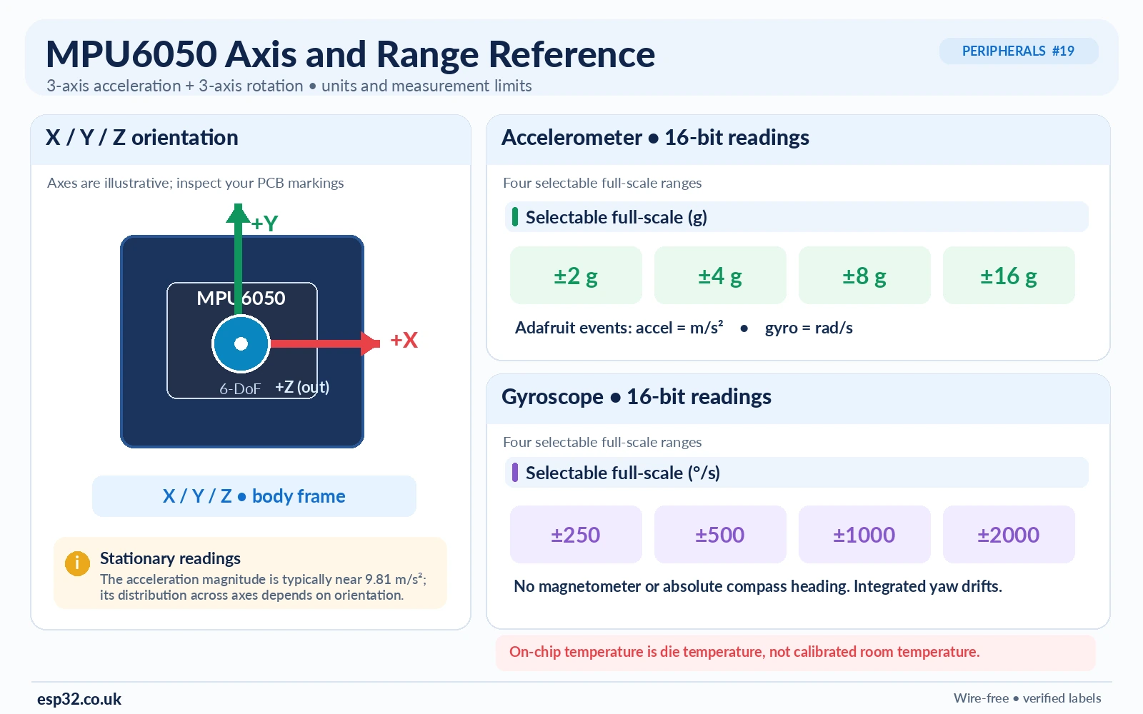
| Accelerometer | ±2, ±4, ±8, ±16 g | Lower range gives finer resolution for small accelerations; higher range avoids clipping |
| Gyroscope | ±250, ±500, ±1000, ±2000°/s | Lower range resolves slow movement; higher range captures faster rotation |
| Digital low-pass filter | Configurable bandwidth, including Adafruit presets such as 5/10/21/44/94/184/260 Hz | Lower bandwidth can reduce noise but also increases smoothing and latency |
| Temperature | On-die internal reading | Useful for diagnostics, not a standalone room sensor |
A sensor tilted relative to gravity will distribute the gravity vector over several accelerometer axes even when not moving. Accelerometer readings alone cannot distinguish arbitrary linear movement from tilt, and an accelerometer does not directly measure displacement or position. The six axes are not “six independent location coordinates”; they are three accelerations and three rotational velocities.
Optional INT pin: data-ready and motion detection
The GY-521 breakout exposes INT; the Adafruit module also provides it. The MPU6050 can signal configurable events instead of forcing the ESP32 to poll constantly. The register map includes interrupt-enable, interrupt-status and interrupt pin-configuration registers. Interrupt level, latching and clear behavior are configurable; do not assume the signal always pulses low or that connecting INT alone enables motion detection.
For an advanced ESP32 example, one can route MPU6050 INT → ESP32 GPIO27 as a logic input, but only after verifying breakout voltage levels and implementing the corresponding MPU6050 interrupt setup. The basic sketch above uses I²C polling and requires no interrupt wire. The auxiliary XDA/XCL pins on GY-521 are a different bus and should not be connected to the ESP32 host SDA/SCL for normal MPU6050 readings.
The built-in DMP is a different feature from reading raw or scaled gyro and acceleration values. DMP setup requires its own supported firmware/software path; Adafruit_MPU6050::getEvent() does not magically produce drift-free 3D orientation or quaternion output. For a beginner, first validate the six-axis raw measurements before attempting fusion.
Common MPU6050 / GY-521 troubleshooting
| Problem | Likely cause and action |
|---|---|
| No I²C reply at 0x68 | Check VDD on the board, ESP32 SDA/SCL assignments, missing ground and cable continuity; scan also 0x69. |
| 0x69 works but 0x68 does not | AD0 is HIGH or Adafruit address solder bridge is closed; update MPU_ADDR. |
| WHO_AM_I is 0x68 but board address is 0x69 | Normal for genuine MPU6050 behavior: ID register does not include the AD0 selectable bit. |
| Sensor found but values freeze or reset | Marginal GY-521 regulator at the selected input voltage, noisy supply, I²C integrity or unsuitable sensor initialization. |
| Gyro moves but readings are in rad/s | Adafruit library exposes SI units; multiply by 57.2958 for degrees/s. |
| Accelerometer at rest is approximately 9.8 | Normal gravity vector, not a sensor defect. |
| Large long-term heading drift | Gyro bias integration; the MPU6050 has no magnetometer for absolute yaw. |
| INT never changes | The interrupt function may not have been configured or the event condition never met; check register settings and polarity. |
| XDA/XCL connected to ESP32 I²C | Those are auxiliary bus pins. Move host SDA/SCL to main SDA/SCL. |
| I²C read erratic when powered at 5 V | Investigate GY-521 pull-ups and logic levels. The sensor chip and ESP32 are not 5 V tolerant. |
MPU6050 versus newer IMUs
MPU6050 boards are inexpensive and widely documented, making them suitable for entry-level motion detection, tilt demonstrations and basic gyro experiments. For a design where supply availability, power consumption and current vendor support matter, compare currently offered IMUs from TDK InvenSense, Bosch or STMicroelectronics. Devices with onboard magnetometers or supported sensor-fusion software may fit robust orientation applications better than a standalone MPU6050. Avoid selecting a chip only because a low-cost GY-521 module is easy to find.
If you need several MPU6050 boards with the same address, see the TCA9548A multiplexer reference. For diagnosing a missing sensor, use the ESP32 I²C scanner guide.
Frequently asked questions
Is MPU6050 an I²C or SPI sensor?
The MPU6050 communicates through I²C. The closely related MPU6000 supports additional SPI functionality; do not assume every MPU-60×0 listing has identical bus options.
Does the GY-521 need 5 V?
Not universally. Some breakout boards accept 5 V at VCC through a regulator, while the raw chip runs at low voltage. Verify the actual breakout regulator, voltage drop and SDA/SCL pull-ups. An Adafruit MPU6050 breakout can be powered at 3.3 V VIN for an ESP32, whereas a particular generic module may need extra checks.
How do I use two MPU6050 sensors?
Give one address 0x68 and the other 0x69 by setting AD0 differently, then initialise each with its own software object and address. A multiplexer solves further address conflicts.
Does MPU6050 measure angles directly?
No. It measures acceleration and angular velocity. Estimating pitch/roll requires trigonometry and filtering, and integrating gyro data drifts. Absolute yaw requires an external reference.
Does the Adafruit library use degrees per second?
No. getEvent() delivers gyroscope rates in radians per second and acceleration in metres per second squared through the Unified Sensor API.
Verified datasheets, board documentation and library
- Adafruit MPU6050 breakout pinouts — voltage regulation, STEMMA QT, address bridge and optional pins.
- Adafruit Arduino usage — I²C setup and library installation.
- Adafruit MPU6050 library source — begin(), getEvent(), range and filter methods.
- TDK InvenSense MPU-6000/6050 product specification — electrical range, sensing ranges and operating modes.
- MPU-6000/6050 register map — WHO_AM_I and interrupt registers.
- GY-521 illustrated module reference — common eight-pin silk-screen signal names.
Hardware scope: The main pinout refers to the GY-521 eight-position module and the separately documented Adafruit breakout. Generic clones may differ in component population, regulator type, address strap or pull-ups. Always check the printed PCB labels and supply voltages on the exact module you are using. The Arduino sketch was checked against the published Adafruit library API but has not been bench-tested here.