
The BH1750AliExpress price digital ambient-light sensorAliExpress price measures illumination directly in lux (lx) over I²C. The inexpensive blue GY-302 module is popular with ESP32AliExpress price projects because it needs only power, ground, SDA and SCL. Unlike a simple photoresistor, it reports a digital measurement: no analogue calibration curve or ESP32 ADC channel is necessary. This board-level reference covers the real GY-302 pinout, its address-select pin, the Adafruit STEMMA QT board variant, ESP32 wiring, a functional schematic, and a complete Arduino example.
Quick wiring: on a classic ESP32-WROOM DevKit, connect 3V3 → VCC, GND → GND, GPIO21 → SDA, and GPIO22 → SCL. Leave ADDR in its default LOW state for address 0x23; tie ADDR HIGH to the sensor logic supply for address 0x5C. The GPIO choices are an ESP32 DevKit example, not universal defaults for every ESP32 family.
BH1750 versus a photoresistor: what do you get?
BH1750 is a digital lux sensor manufactured originally by ROHM. Its integrated photodiode, signal processing and ADC produce a 16-bit count that software converts into an illumination estimate. It is designed for ambient-light measurements with a spectral response approximating human brightness perception. You can use it to dim a display, record day/night conditions, monitor room lighting or trigger an automated blind. It does not measure colour temperature, RGB colour, UV radiation, motion or direct sunlight power in W/m².
| Property | BH1750 / typical GY-302 |
|---|---|
| Interface | Two-wire I²C (SDA, SCL); no SPI interface |
| Reported quantity | Illuminance in lux (lx), not raw ESP32 ADC voltage |
| Conversion | 16-bit output data; mode determines effective resolution |
| Default I²C address | 0x23 with ADDR low or board default |
| Alternate address | 0x5C with ADDR tied high |
| High-resolution mode | Nominal 1 lx resolution; around 120 ms conversion |
| High-resolution mode 2 | Nominal 0.5 lx resolution; around 120 ms conversion |
| Low-resolution mode | Nominal 4 lx resolution; around 16 ms conversion |
| Typical module supply | Depends on PCB; many GY-302 boards labelled 3–5 V and include an LDO regulator |
| BH1750 chip supply | Approximately 2.4–3.6 V; never apply 5 V directly to the bare chip |
| Bus frequency | Standard 100 kHz I²C is a conservative, easy-to-debug setting |
| Maximum reading | Finite 16-bit readout; saturates under sufficiently bright conditions; not a laboratory lux meter |
Some GY-302 product descriptions call the sensor “16-bit” and simultaneously give a 1 lx or 0.5 lx resolution. There is no contradiction: 16-bit describes the returned value width; measurement-mode timing and scale determine the nominal lux increment. Accuracy is affected by sensor tolerance, spectral content, mounting angle and any protective cover.
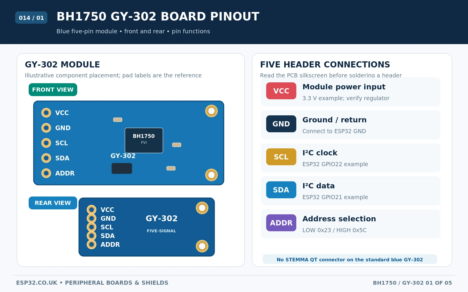
GY-302 BH1750 pinout: the five signals
On a widely sold GY-302 PCB, the backside silkscreen lists VCC, GND, SCL, SDA, ADDR down the five-hole header. This is the order when viewed as in the supplied board-reference image, not a promise about how a rotated or differently made board appears on your bench. Always follow the actual PCB printing.
| GY-302 marking | Function | Classic ESP32 DevKit connection |
|---|---|---|
| VCC | Breakout supply, often via onboard 3.3 V regulator | 3V3 for the recommended example; verify your variant works at this input |
| GND | Power and signal ground | GND |
| SCL | I²C clock | GPIO22 |
| SDA | I²C data | GPIO21 |
| ADDR / ADD | Hardware address selection | Leave as board default LOW for 0x23; HIGH for 0x5C |
The GY-302 is not identical to the smaller GY-30, the Adafruit BH1750 STEMMA QT breakout or other clones. In particular, never assume that every board has the same voltage regulator, MOSFET level-shifters, pull-up resistor values or solder-bridge locations. These are properties of the PCB, not the BH1750 silicon. The GY-302 front and rear photographs in the Addicore module listing are useful for identifying the five-pin version.
Adafruit STEMMA QT pinout is different
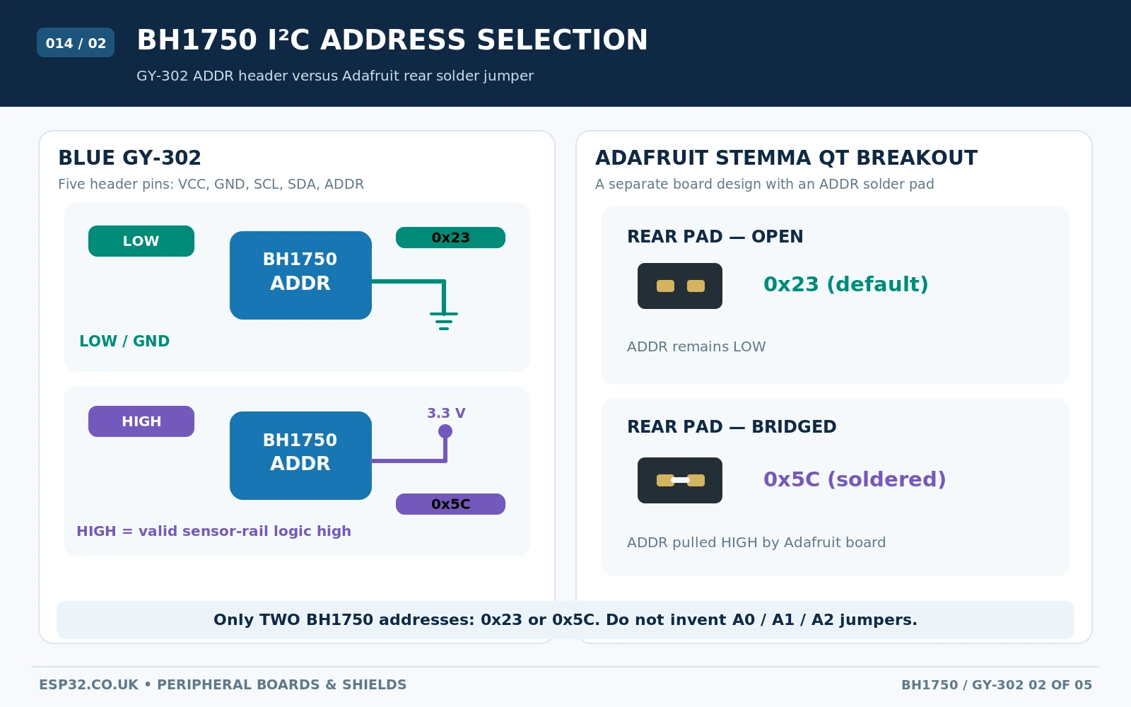
The official Adafruit BH1750 breakout exposes VIN, 3Vo, GND, SCL, SDA, a dedicated ADDR pin and two STEMMA QT / Qwiic connectors. It includes 3–5 V input regulation and I²C level translation. The 3Vo pin is the regulator output—not an additional 5 V supply input. The Adafruit board has a labelled rear ADDR solder jumper; generic GY-302 boards usually instead provide an ADDR header pin. The chip works the same way, but the physical board layouts and supply circuits should not be mixed.
BH1750 I²C address: 0x23 versus 0x5C
The sensor has two valid I²C addresses. The ADDR hardware input selects one at start-up, and the Arduino library must be configured to match it. This is not a range of consecutive addresses such as 0x20–0x27, nor a programmable I²C register. The device does not have address bits A0/A1/A2 like an MCP23017.
| ADDR state | 7-bit address | Typical configuration |
|---|---|---|
| LOW / connected to GND | 0x23 | Default GY-302; leave unused if board already pulls ADDR low |
| HIGH / connected to sensor VCC | 0x5C | Tie GY-302 ADDR to the appropriate module logic supply, or bridge Adafruit rear ADDR jumper |
Important: “leave ADDR floating” works on many modules because the board holds it low, but should not be treated as a universal bare-chip rule. If your board has no documented pull-down, explicitly give ADDR a defined LOW level. Do not bridge unknown solder pads merely because they resemble those on the Adafruit PCB.
Can two BH1750 sensors share an ESP32 I²C bus?
Yes. Connect both modules in parallel to the same 3.3 V, ground, SDA and SCL signals, then configure one as 0x23 and the other as 0x5C. They must have different addresses. For three or more BH1750 devices you normally need separate I²C buses or a multiplexer such as the TCA9548A, because there are only two BH1750 addresses.
Functional schematic: module power, I²C pull-ups and ADDR
The bare BH1750FVI is a 3.3 V-class integrated sensor with its own digital I²C interface. A practical circuit connects the sensor supply to an approved 3.3 V rail, provides local bypass capacitors, uses SDA and SCL pull-up resistors referenced to the intended I²C logic voltage, and holds the address input low or high for the chosen address. Actual chip support connections such as the DVI pin and regulator configuration must follow the device datasheet and the selected breakout design.
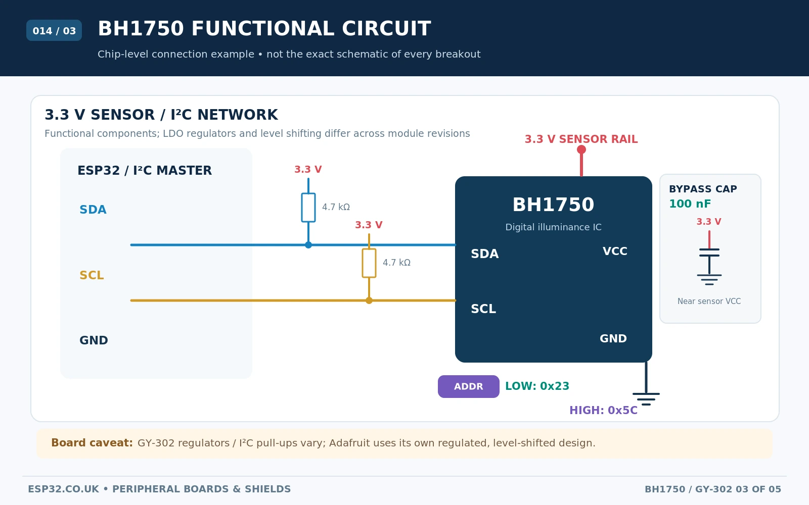
3.3 V versus 5 V: many GY-302 boards include a regulator and are labelled 3–5 V; Adafruit adds verified input regulation and level shifting. The BH1750 IC itself must remain within its lower supply-voltage limits. A board with only 5 V-rated headers is not necessarily 5 V-safe on SDA/SCL. For direct ESP32 wiring, use 3.3 V on both the logic and breakout supply if the module supports it, and confirm the I²C idle voltages with a multimeter when using an unfamiliar clone. If a particular regulator has significant dropout at 3.3 V, power the actual sensor rail appropriately instead of guessing.
I²C is an open-drain bus: SDA and SCL require pull-ups, but multiple modules can contain pull-ups already. With many devices in parallel, the combined resistance falls. Do not add strong pull-ups blindly. A conservative 100 kHz bus and short wiring make initial testing easier.
ESP32 and GY-302 wiring diagram
| ESP32 pin | GY-302 | Purpose |
|---|---|---|
| 3V3 | VCC | Module power for a compatible 3.3 V breakout |
| GND | GND | Common return and logic reference |
| GPIO21 | SDA | I²C data (classic ESP32-WROOM board example) |
| GPIO22 | SCL | I²C clock (classic ESP32-WROOM board example) |
| Unconnected if onboard pull-down is fitted | ADDR | Default 0x23; for 0x5C connect to the module’s appropriate HIGH rail |
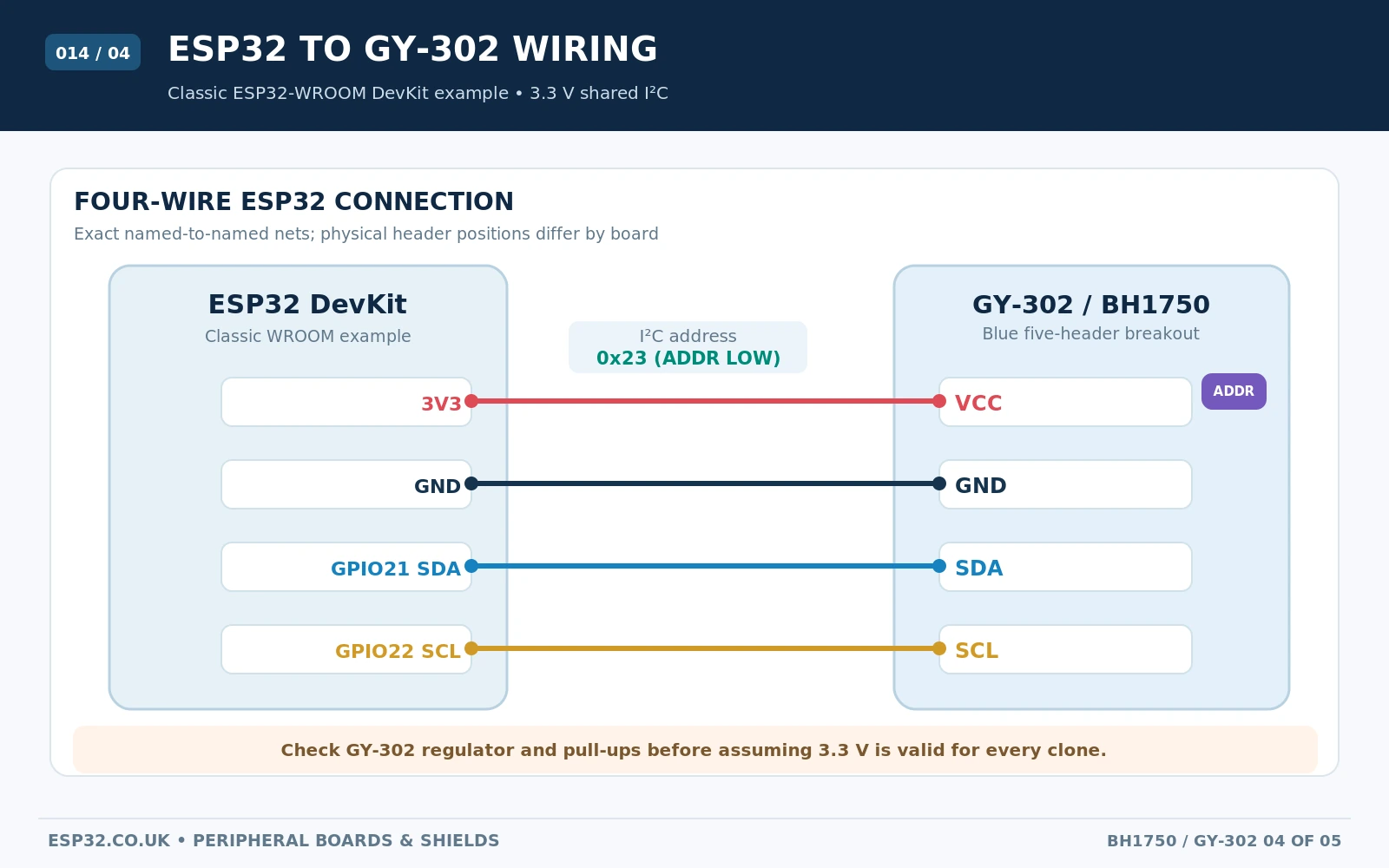
The ESP32-C3, S3, C6 and other variants may use different GPIOs. Pick two usable I²C pins for your specific board and change the constants in the example. Do not copy the GPIO21/22 connections onto every ESP32 model without checking its pinout and reserved/boot pins.
Arduino IDE example using the Christopher Laws BH1750 library
For this standalone ESP32 guide, use the widely adopted BH1750 by Christopher Laws (claws/BH1750) library from Arduino Library Manager. It provides the BH1750 class, begin(), readLightLevel() and measurement modes listed below. Adafruit instead recommends the hp_BH1750 library for its own tutorial; the code in this article is not the hp_BH1750 API. Choose one library and follow the matching example.
This example uses 3.3 V, the default 0x23 address and continuous high-resolution mode. It checks initialization and negative return codes so missing sensors do not silently appear as real lux values. Keep the sensor exposed to light rather than covering it with opaque foam or a case.
#include <Arduino.h>
#include <Wire.h>
#include <BH1750.h>  // Library: BH1750 by Christopher Laws

constexpr int I2C_SDA = 21;          // Classic ESP32 DevKit
constexpr int I2C_SCL = 22;
constexpr uint8_t BH1750_ADDRESS = 0x23;

BH1750 lightMeter;

void setup() {
  Serial.begin(115200);
  delay(500);

  Wire.begin(I2C_SDA, I2C_SCL);
  Wire.setClock(100000);

  if (!lightMeter.begin(BH1750::CONTINUOUS_HIGH_RES_MODE,
                        BH1750_ADDRESS, &Wire)) {
    Serial.println("BH1750 not detected/configured.");
    Serial.println("Check VCC, GND, SDA, SCL and ADDR state.");
    while (true) delay(1000);
  }

  Serial.printf("BH1750 ready at 0x%02X.\n", BH1750_ADDRESS);
}

void loop() {
  float lux = lightMeter.readLightLevel();

  if (lux >= 0.0f) {
    Serial.printf("Ambient light: %.1f lx\n", lux);
  } else {
    Serial.printf("BH1750 read error: %.0f\n", lux);
  }

  delay(1000);
}
If you tie ADDR HIGH, change BH1750_ADDRESS to 0x5C before uploading the program. To use two sensors, create two separate BH1750 instances and initialise one at each address using the same &Wire. The two sensors do not need separate SDA/SCL pins when they have different addresses.
Example serial output
BH1750 ready at 0x23.
Ambient light: 21.7 lx
Ambient light: 22.5 lx
Ambient light: 135.8 lx
Ambient light: 428.3 lx
Ambient light: 427.5 lx
These numbers are illustrative output, not a physical test of a particular module. Under normal lighting, readings usually rise as the sensor is moved towards a brighter light source. They can vary with direction, reflections and colour temperature.
Continuous versus one-time BH1750 measurements
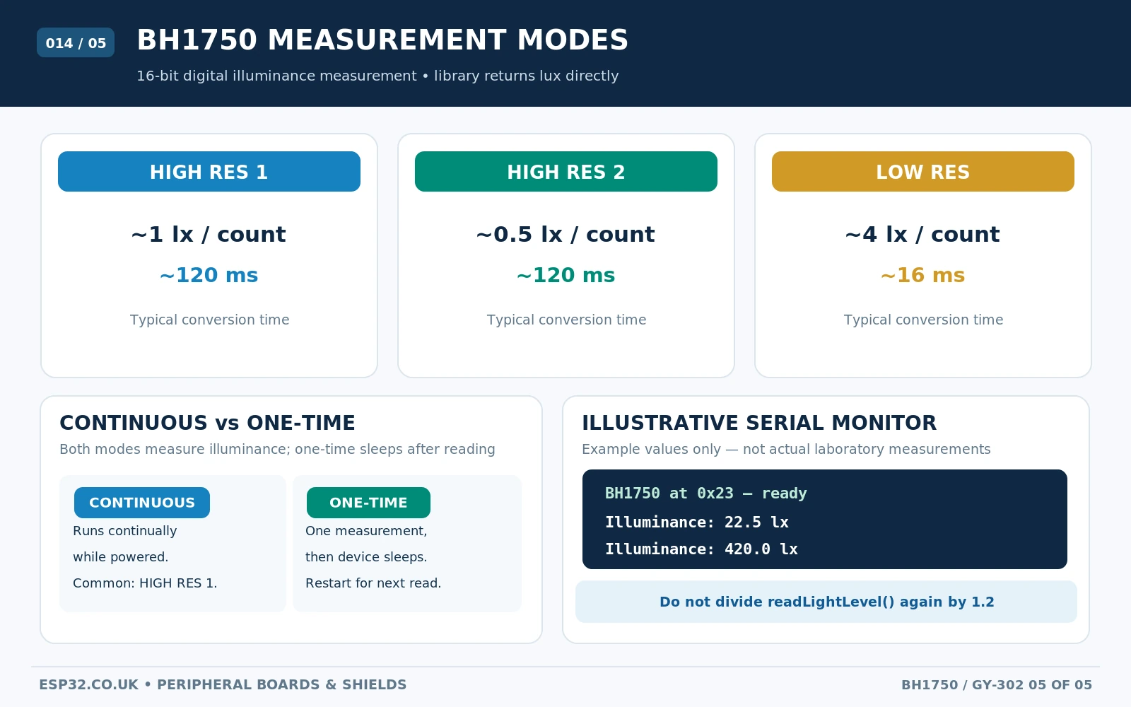
| Library mode | Nominal resolution | Typical conversion time | Use case |
|---|---|---|---|
| CONTINUOUS_HIGH_RES_MODE | 1 lx | ~120 ms | General room lighting; good default |
| CONTINUOUS_HIGH_RES_MODE_2 | 0.5 lx | ~120 ms | Darker scenes and finer steps |
| CONTINUOUS_LOW_RES_MODE | 4 lx | ~16 ms | Faster, less detailed readings |
| ONE_TIME_HIGH_RES_MODE | 1 lx | ~120 ms | Infrequent measurements / low-power polling |
| ONE_TIME_HIGH_RES_MODE_2 | 0.5 lx | ~120 ms | Infrequent finer-resolution readings |
| ONE_TIME_LOW_RES_MODE | 4 lx | ~16 ms | Fast one-time sample |
The sensor returns a 16-bit reading; library scaling converts that to lux. With the usual measurement-time register configuration, a common conversion relationship is approximately lux = raw_count / 1.2. The library handles the count conversion for you; do not divide its reported lux by 1.2 again. Individual devices can require calibration for accurate photometry.
Continuous mode repeatedly measures light; one-time mode completes a measurement and returns to a low-power state. One-time operation is useful for a battery-powered design, but the ESP32’s own deep sleep, regulator quiescent current and wireless activity often dominate total energy use. Measurement-time adjustments change resolution, conversion time and maximum unsaturated reading, so do not equate a 16-bit register with unlimited measurement range.
Troubleshooting: address missing, 0 lx or strange readings
| Symptom | Possible cause and fix |
|---|---|
| I²C scanner finds nothing | Check VCC and ground, correct SDA/SCL routing, pull-ups, module variant and actual ESP32 pins. Try 100 kHz. |
| Device appears at 0x5C, not 0x23 | ADDR is being held HIGH or the Adafruit ADDR bridge is soldered; change the code address accordingly. |
| Two sensors both appear at 0x23 | Their ADDR pins are not different; pull one HIGH for 0x5C or use a multiplexer. |
| Reading is always 0 lx | Sensor may be completely dark, not configured, behind an opaque lid, on wrong I²C address or incorrectly powered. |
| Reading negative | Christopher Laws library uses negative return codes for invalid or unconfigured readings; check communication. |
| Readings jump in artificial lighting | Flicker, shadows, reflective surfaces or measurement timing may affect results; average samples if appropriate. |
| Readings plateau in bright sunlight | Sensor/count saturation, optical orientation or measurement setting. Avoid interpreting a saturated value as the exact illuminance. |
| ESP32 is unstable on a 5 V module | Potential logic-voltage mismatch or excessive pull-up voltage; use appropriate 3.3 V-level I²C wiring. |
| Adafruit board does not look like GY-302 | It is a different breakout: VIN/3Vo/STEMMA QT and rear solder jumper are Adafruit-specific. |
Why does a BH1750 show light even in the dark?
A digital lux reading can reflect small amounts of ambient leakage, display glow or sensor noise. The result depends on shielding, integration mode and sensor tolerances. It is not evidence that the device measures infrared heat or has a proximity sensor. Before diagnosing an electronics fault, verify the test enclosure is actually light-tight.
Is the BH1750 accurate enough for a light switch?
Usually yes for a coarse automation threshold such as “dark enough to turn on lights,” provided you choose the placement sensibly and add hysteresis to avoid rapid switching near the threshold. For example, switch lights on below 50 lx and off only above 100 lx, with a short delay. For regulated lighting and professional lux measurements, use a calibrated instrument and account for mounting geometry.
BH1750 versus BH1750 ESPHome and Home Assistant setups
This article intentionally focuses on the physical board, address selection, schematic and minimal Arduino sketch. For an automation-system configuration, see the existing BH1750 with ESPHome and Home Assistant guide. The two guides have complementary search intent, so do not clone the same ESPHome YAML into the board reference.
Other useful related modules are the TCA9548A I²C multiplexer for extra BH1750 sensors with duplicate addresses, and a BME280 temperature/humidity/pressure breakout when environmental monitoring beyond light is needed. The BH1750 measures illuminance, not temperature or humidity.
BH1750 FAQs
Does the BH1750 need an analogue input?
No. It is a digital I²C device; the ESP32 only needs SDA, SCL, power and ground. Leave ESP32 ADC pins free for other sensors.
Is BH1750 address 0x23 or 0x5C?
Both are possible, but not simultaneously on one sensor. ADDR LOW selects 0x23 and ADDR HIGH selects 0x5C. The address does not come from software alone.
Does GY-302 have an I²C address solder jumper?
The familiar blue GY-302 normally has a fifth ADDR header pin; the Adafruit STEMMA QT BH1750 breakout has a dedicated rear address solder pad. Do not mistake the mounting holes or SMD resistors of a GY-302 for selectable address jumpers.
Can BH1750 be connected directly to ESP32 with 5 V?
A given breakout may accept 5 V as its supply if it contains proper regulation, but bare BH1750 chips are not 5 V devices and ESP32 GPIOs are not 5 V tolerant. The conservative example powers a verified compatible breakout at 3.3 V. Check the board’s regulator and I²C pull-up arrangement before using 5 V.
Can BH1750 measure sunlight?
It can sense ordinary daylight, but the output has a finite range and can saturate in very bright conditions. The maximum usable lux also depends on the chosen mode and measurement-time setting. It cannot report solar irradiance in W/m².
Datasheets, board documentation and code references
- Adafruit BH1750 breakout pinouts — regulator, level shifting, 3Vo, STEMMA QT and rear ADDR jumper.
- Adafruit Arduino learning guide — manufacturer recommends hp_BH1750 for its tutorial.
- Christopher Laws BH1750 Arduino library — mode names, I²C address selection and readLightLevel API used in this article.
- BH1750.h API reference — begin(mode, address, TwoWire*) signature and measurement modes.
- Common GY-302 module photographs — blue five-pin breakout front/back identification.
- GY-302 module reference photos — pin silk-screen and board variants.
Board-revision disclosure: This reference applies principally to the common blue GY-302 and separately describes the genuine Adafruit BH1750 breakout. Component positions, voltage regulators, pull-up values, and unlabelled pads must be verified for the specific PCB version in hand. The code was checked against the published Arduino library API but was not bench-tested on the reader’s particular hardware.