Quick answer: The STM32F103C8PriceAliExpress price Blue PillPriceAliExpress price can appear on Windows, Linux or macOS as a USB CDC-ACM virtual serial port without an external USB-to-UART converter. Its USB full-speed device signals are PA11 = USB D− and PA12 = USB D+. In STM32CubeMX, configure a valid 48 MHz USB clock, enable USB Device FS, add the USB_DEVICE → Communication Device Class (CDC) middleware, generate the project and flash it using ST-LINKPriceAliExpress price over SWD. The application can then send text through CDC_Transmit_FS() and receive bytes through the generated CDC_Receive_FS() callback. A working USB cable and a correctly implemented D+ pull-up are essential.
In this esp32.co.uk/ tutorial, we go beyond making a COM port appear. We separate hardware wiring, USB enumeration and application data transfer; build a complete greeting and echo application; explain transmit-busy handling and receive buffering; and troubleshoot everything from an absent COM port to a stalled USB endpoint. The instructions target the classic STM32F103C8T6 Blue Pill with STM32CubeMX, STM32CubeIDE 2.x, the STM32F1 HAL and ST’s classic USB device library. USB support and code-generation names may vary with the STM32Cube package version. The examples have been checked against documentation and API structure, not physically bench-tested.
What USB CDC actually does
A conventional serial port transmits asynchronous bits over TX and RX lines. A USB CDC-ACM virtual COM port instead presents a USB interface that the operating system treats like a serial terminal. The PC opens COMx, /dev/ttyACM* or /dev/cu.usbmodem*, while the STM32 firmware exchanges USB packets over D+ and D−. No UART start bit, stop bit or hardware baud clock is present on those USB wires.
That distinction matters because beginners often confuse three separate items: the Blue Pill’s built-in USB device peripheral, a USB-to-UART converter such as CP2102, and a factory USB bootloader. The F103C8 has the first, usually has neither of the other two, and does not acquire them just because the Micro-USB connector provides power. To use the USB peripheral as a COM port, it must run suitable application firmware. To install that firmware on a fresh board, use SWD or the factory USART1 ROM loader.
USB CDC is particularly useful for diagnostics, configuration menus, data logging to a host, command consoles, simple instrument links and communication with Python programs. In comparison with a UART adapter it saves hardware, but it also introduces USB clocks, host enumeration, middleware state and packet-buffer handling that a three-wire TTL UART does not require.
| Feature | Native STM32 USB CDC | USART1 with USB-UART adapter |
|---|---|---|
| MCU signals | PA11 D−, PA12 D+ | PA9 TX, PA10 RX |
| External converter | Not required | Required at PC side |
| Host device type | USB CDC ACM, virtual COM port | USB serial bridge COM port |
| USB clock in MCU | Precise 48 MHz | Not required for USART alone |
| Firmware support | USB device stack and CDC class | HAL UART or equivalent |
| Terminal baud setting | Usually advisory line-coding metadata | Controls actual UART bit timing |
| Fresh F103 ROM firmware loading | Not via factory USB DFU | USART1 ROM loader available |
| Typical first-time debugging | SWD, host USB device list and CDC messages | USB adapter and crossed serial wires |
An important limitation is that CDC virtual serial is not a promise of deterministic timing. The USB host schedules transactions, the device stack buffers data, and the operating system can pause or coalesce reads. Use timer input capture for precise edges and a hardware UART for a direct serial timing interface where appropriate.
Hardware: the exact Blue Pill USB signals
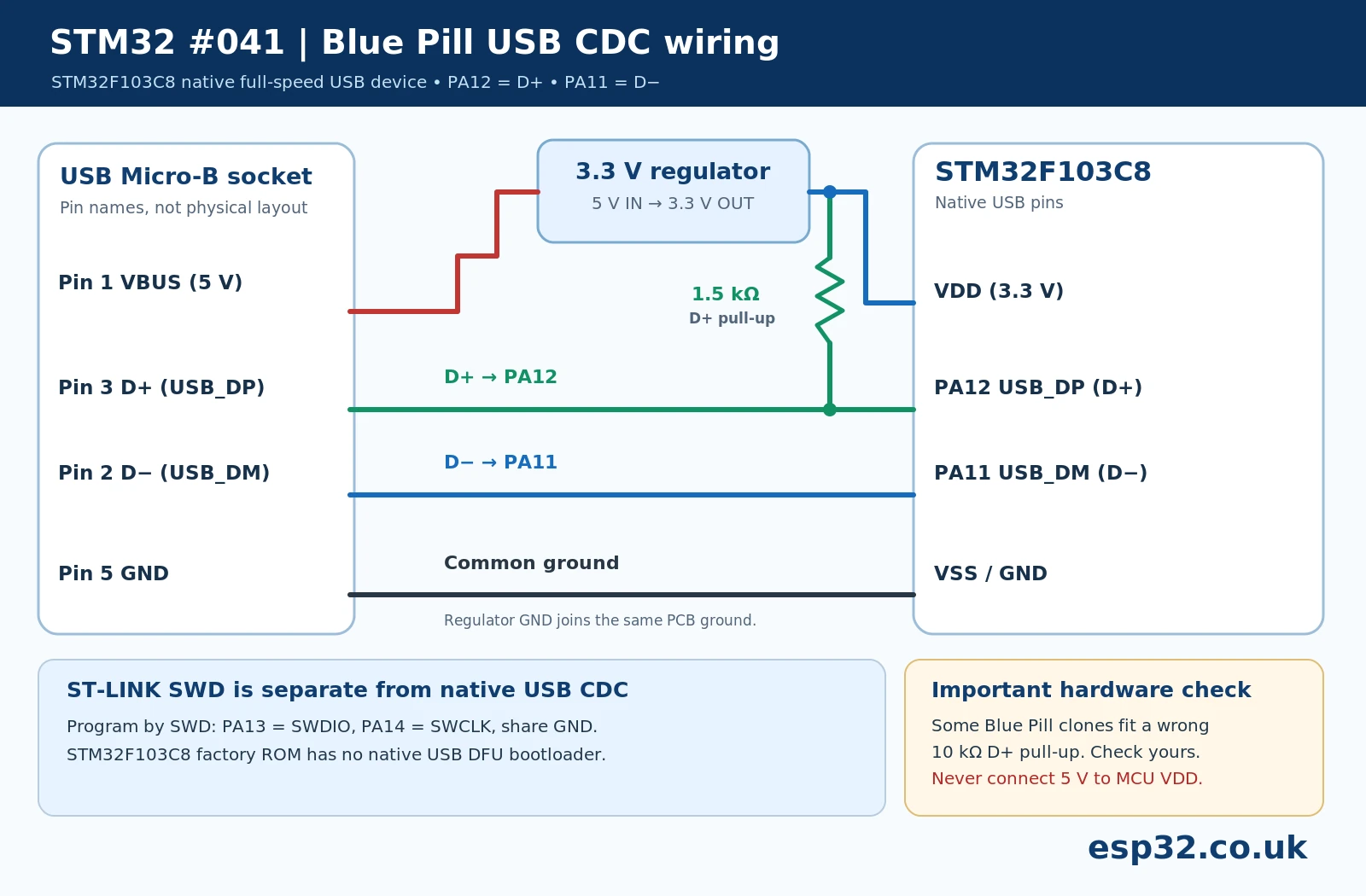
The standard STM32F103C8 peripheral includes a USB 2.0 full-speed device-only interface. On the typical Blue Pill, the Micro-USB connector feeds the MCU data lines and supplies the board regulator. This is a target USB device port, not the USB socket on an ST-LINK adapter.
| USB or power net | F103C8 MCU signal | Practical check |
|---|---|---|
| USB data minus | PA11, USB_DM | Goes to Micro-USB D− through PCB routing |
| USB data plus | PA12, USB_DP | Goes to Micro-USB D+ and external full-speed attach pull-up |
| USB connector 5 V | Board’s VBUS / 5 V rail | Normally feeds onboard 3.3 V regulator, board-dependent |
| Device logic supply | MCU VDD, typically 3.3 V | Must remain within datasheet supply limits |
| USB and MCU ground | GND | Common reference across host and target |
| Debug data | PA13 SWDIO, PA14 SWCLK | External ST-LINK, separate from USB D+/D− |
Do not connect USB 5 V directly to PA11, PA12 or the 3V3 rail. Use the actual board schematic before mixing external 5 V and USB power. Cheap Blue Pill revisions often lack protection against backfeeding between the USB 5 V connection and other power inputs. For a first test, power the board through one known USB source and connect SWD ground plus target-voltage reference without injecting a second supply.
A full-speed USB device signals attachment by pulling D+ up to 3.3 V through approximately 1.5 kΩ. On F103 USB designs this is an external pull-up, unlike some later STM32 families. On certain inexpensive Blue Pill variants, the part frequently identified as R10 is 10 kΩ or 4.7 kΩ instead. Those values may cause inconsistent or failed enumeration. The actual resistor designation is PCB-revision dependent: inspect the schematic or measure the D+ pull-up circuit before any modification. A wrong resistor is a board-assembly defect and is not proof that the microcontroller itself is counterfeit.
USB cables also deserve suspicion. A charge-only Micro-USB cable will happily light the Blue Pill power LED while delivering no data connection. Use a known-good data cable and connect directly to the PC before trying drivers, reprogramming or solder rework. A visibly powered device and a successfully enumerated USB device are different observations.
Equipment and software
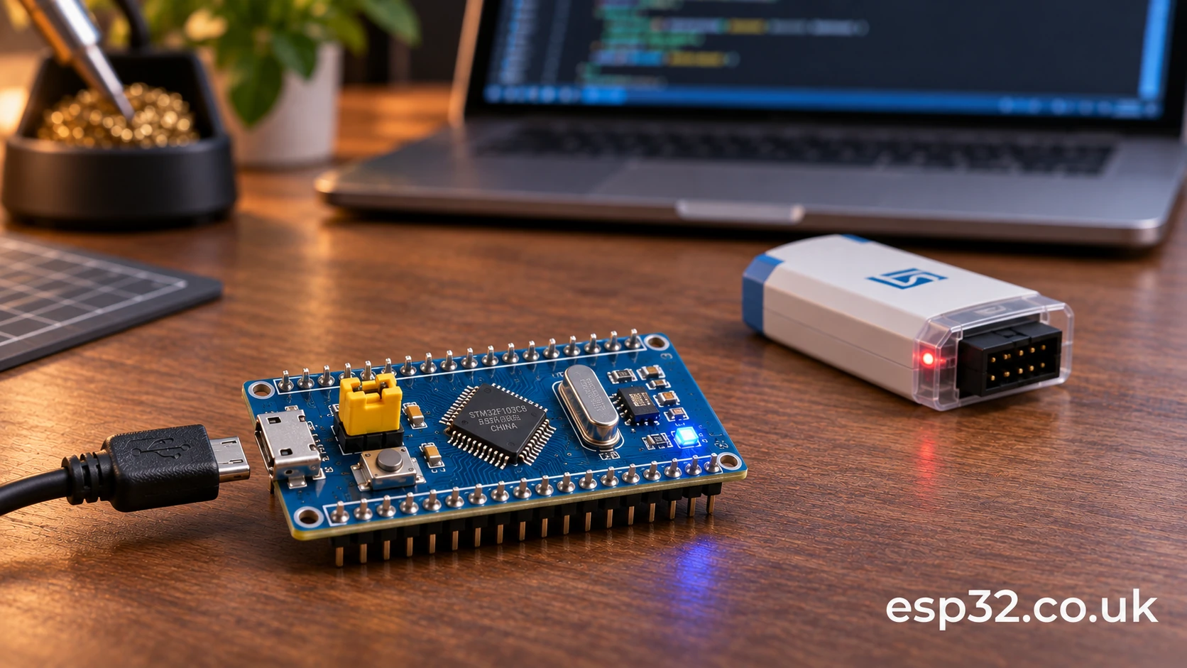
For the reproducible demonstration use a genuine or documented compatible STM32F103C8 Blue Pill with an 8 MHz HSE crystal, a data-capable Micro-USB cable, an ST-LINK probe with verified SWD pinout, and a Windows, Linux or macOS computer. A logic analyser or oscilloscope is optional; the first successful test should need neither. The exact ST-LINK connector depends on the probe, particularly if it is a clone dongle.
Install STM32CubeMX, the matching STM32CubeF1 firmware package, STM32CubeIDE 2.x, and STM32CubeProgrammer where needed. As in our STM32CubeIDE setup guide, newer CubeIDE 2.x versions use a separate CubeMX configuration and generation workflow: create the project with CubeMX and import it into the IDE. Choose matching package releases instead of blindly mixing examples from very old tutorials with new generated files.
The host needs a serial terminal such as PuTTY, Tera Term, minicom, screen or a Python script using pyserial. A serial terminal is only useful after the board has enumerated as CDC. If Device Manager or the USB device list cannot see a proper USB device at all, terminal settings are not the first problem to solve.
The required 48 MHz USB clock
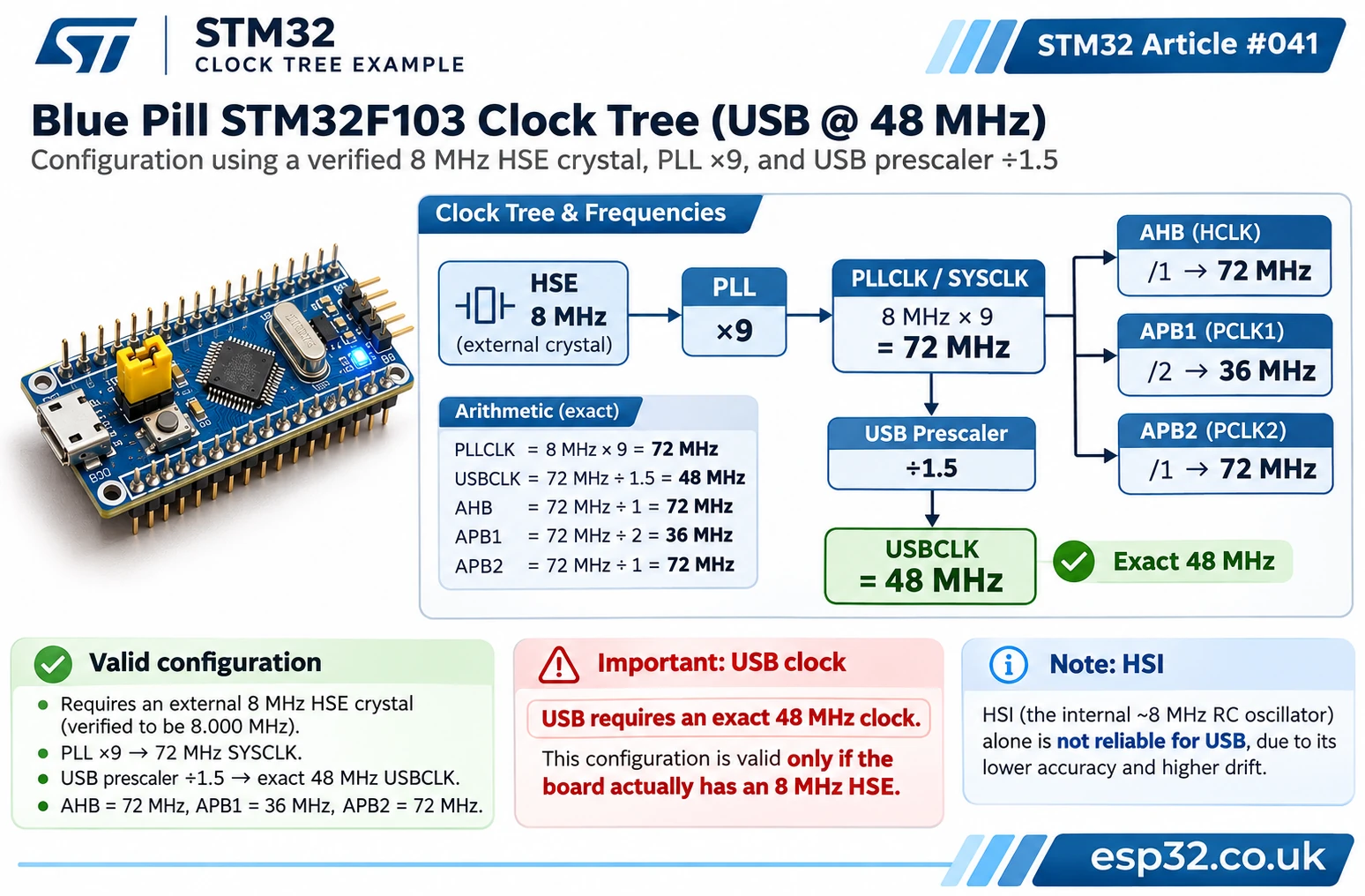
The F103 USB controller requires an accurately derived 48 MHz clock. Ordinary GPIO code may work with a misconfigured system clock, making USB clock errors look like a mysterious hardware problem. On the common Blue Pill with an 8 MHz HSE crystal, a straightforward 72 MHz core and 48 MHz USB configuration is:
| Clock stage | Example value | Explanation |
|---|---|---|
| HSE crystal | 8 MHz | Confirm the actual component fitted to the board |
| PLL source | HSE | Use stable external clock reference |
| PLL multiplier | ×9 | 8 × 9 = 72 MHz PLLCLK |
| AHB prescaler | ÷1 | 72 MHz HCLK/SYSCLK |
| APB1 prescaler | ÷2 | 36 MHz PCLK1, within F1 limit |
| APB2 prescaler | ÷1 | 72 MHz PCLK2 |
| USB prescaler | ÷1.5 | 72 ÷ 1.5 = 48 MHz USBCLK |
This is an example for verified 8 MHz HSE hardware, not a universal setting for every STM32 board. Check the crystal marking and STM32CubeMX clock view. The internal HSI oscillator is convenient for non-USB tests but is generally not a suitable accurate clock source for this particular F103 USB setup without additional provisions. Other STM32 families may have independent calibrated 48 MHz oscillators; do not carry their clock recipes across without checking the device reference manual.
An apparently correct 48 MHz number in the configurator is not enough if the physical crystal fails to start. If USB remains undetected while the application runs, verify oscillator startup status, power rails, the chosen clock source and the resulting RCC configuration before trusting the value shown in a tutorial screenshot.
Create the project in STM32CubeMX
Open CubeMX, select the STM32F103C8Tx part (or the exact valid variant that matches the board), and create a project. For the primary USB test, keep the MCU configuration minimal: USB CDC, debug support and the right clock. Additional sensors, timers and CAN configurations only make initial fault isolation harder.
In System Core → SYS, select Serial Wire debug. This leaves PA13 and PA14 available for SWD so USB development can be recovered without relying on working USB firmware. In System Core → RCC, enable the HSE crystal oscillator and confirm the correct frequency in Clock Configuration. Set the 72/48 MHz plan above, or another datasheet-valid HSE-derived 48 MHz plan.
Under Connectivity → USB, enable the full-speed device interface. The F103 uses its USB device peripheral, not an OTG host configuration. Where CubeMX offers the USB_DEVICE middleware, choose Communication Device Class (CDC). CubeMX should assign PA11/PA12 to USB, generate a USB device stack and enable the appropriate USB low-priority interrupt integration. Confirm that the middleware actually generates a CDC interface file rather than only a low-level peripheral driver.
In Project Manager, set a stable project name such as F103_BluePill_USB_CDC, choose the STM32CubeIDE toolchain, install the required package if prompted, and generate the code. Import the project using CubeIDE’s existing-project import workflow. Preserve custom code inside designated USER CODE blocks as much as possible, and maintain a version-controlled copy of the .ioc configuration. Some generated function names or file paths can change with packages; the principles and HAL/USB API roles remain the same.
| CubeMX section | Target setting | Why |
|---|---|---|
| MCU | STM32F103C8Tx | Right flash, memory and USB peripheral |
| SYS | Debug: Serial Wire | Retain PA13/PA14 for SWD recovery |
| RCC | External crystal HSE | Accurate 8 MHz reference on common Blue Pill |
| Clock tree | SYSCLK 72 MHz / USB 48 MHz | Required full-speed USB clock |
| Connectivity | USB Device FS enabled | Enables PA11/PA12 USB controller |
| Middleware | USB_DEVICE, CDC class | Produces CDC interface and descriptors |
| NVIC | USB low-priority interrupt handling | Host control and data transfers |
| Project manager | STM32CubeIDE | Generates importable project |
If the USB_DEVICE class menu is missing, first verify that the STM32CubeF1 firmware package and device were selected correctly. Newer STM32 lines can have different USB middleware offerings, but this example is for the classic F1 family. Avoid manually copying arbitrary USB library files into a project until you understand the package/version mismatch.
Understand the generated USB files
CubeMX-generated F1 projects typically contain a USB_DEVICE directory with the class interface and initialization, along with the low-level glue connecting the STM32 USB peripheral control driver to the USB device middleware. File names commonly include:
| Generated component | Responsibility |
|---|---|
usb_device.c / .h |
Initializes device stack and registers CDC interface |
usbd_cdc_if.c / .h |
Application-facing CDC transmit, receive and control callbacks |
usbd_desc.c / .h |
USB device strings and descriptors |
usbd_conf.c |
Low-level PCD-to-USB middleware integration |
usbd_cdc.c |
STM32 USB middleware CDC class logic |
main.c |
Application initialization and foreground logic |
stm32f1xx_it.c |
Generated IRQ entry points; leave USB handler wiring intact |
The important division is that CDC_Transmit_FS() submits application data for USB IN transfer, while CDC_Receive_FS() is called when the USB host sends data to the device. FS means full-speed, not a hardware USART number. USB_DEVICE and the generated MX_USB_DEVICE_Init() call must execute after the MCU and relevant clock infrastructure have been initialized. Normally the code generator already places it in the correct startup sequence.
The host and device move USB packets, not newline-delimited text. A single PC write can arrive split into several USB packets or several writes may be coalesced. Application code must cope with arbitrary chunk sizes instead of assuming that one callback equals one command line.
First working example: periodic CDC greeting
Start with a minimal application that proves enumeration and data transmission before adding a receive queue. Place the following include inside /* USER CODE BEGIN Includes */ in Core/Src/main.c:
#include "usbd_cdc_if.h"
After MX_USB_DEVICE_Init() is called in the generated startup, use a stable string buffer and a periodic transmission in the foreground loop. The following belongs inside /* USER CODE BEGIN WHILE */ and the corresponding USER CODE section in the generated loop:
static uint8_t greeting[] = "STM32 USB CDC online\r\n";
uint32_t last_send = HAL_GetTick();

while (1)
{
    if ((uint32_t)(HAL_GetTick() - last_send) >= 1000U)
    {
        last_send = HAL_GetTick();
        /* BUSY before enumeration or during a pending IN transfer is normal. */
        (void)CDC_Transmit_FS(greeting, (uint16_t)(sizeof(greeting) - 1U));
    }

    /* USER CODE BEGIN 3 */
    /* Additional non-blocking application processing goes here. */
    /* USER CODE END 3 */
}
greeting has static storage duration. That matters because the USB middleware may retain the pointer until the asynchronous USB IN transfer completes. Do not pass a temporary stack buffer that is overwritten immediately after scheduling a transfer. The call returns USBD_OK, USBD_BUSY or another result as defined by the middleware; the demo tolerates an occasional busy return rather than blocking in a loop. For high-rate logging, we will use explicit buffering and completion management instead of silently dropping messages.
Important code-generation placement: Keep the skeleton generated by CubeMX. Do not duplicate while (1) or remove MX_USB_DEVICE_Init(); the example replaces the body of the generated while section only. The exact USER CODE labels vary by tool release. If a pre-existing while (1) already exists, insert only the timing logic and its greeting/last_send declarations in appropriate preserved sections.
Build and download the firmware with ST-LINK over SWD. Reset or resume the target, attach the Micro-USB data cable and observe the operating-system USB device list. The PC should enumerate a CDC device; open the corresponding new virtual COM port. After the firmware runs, the terminal should display one greeting approximately every second. This is an expected result to check on hardware, not a claimed measurement from our bench.
Find the CDC port on Windows, Linux and macOS
Windows 10 and 11: Open Device Manager and check Ports (COM & LPT) after connecting the device. A standards-compliant CDC-ACM interface is generally supported by the built-in usbser.sys driver. You may see “USB Serial Device (COM7)” or another port number. An invalid device descriptor is not repaired by manually assigning a COM-port driver, because the host has not successfully enumerated the USB device.
Linux: Run dmesg -w in one terminal, connect the board, and inspect the new device with lsusb. A USB CDC ACM device commonly appears as /dev/ttyACM0 or another ttyACM instance; a USB-UART bridge often creates /dev/ttyUSB0 instead. If the device is listed but permissions block access, check distribution-specific serial groups or another process that may have opened the port.
macOS: Check System Information → USB and inspect /dev/cu.usbmodem* entries. Use the cu device for an outgoing terminal connection where appropriate. The exact device path changes with the USB descriptor strings, connected devices and operating-system state.
For USB CDC, selecting 115200 8N1 in a terminal is a familiar convention but does not set the PA11/PA12 USB bus bit rate. The host sends CDC line-coding metadata that firmware could use to configure a separate UART bridge, but this direct CDC greeting application does not use any hardware USART. If a host terminal opens the port at 9600 or 115200, the USB packets remain full-speed USB transactions. Do not diagnose a USB enumeration failure by changing virtual COM baud values.
Echo incoming characters without blocking the USB callback
The next example shows a genuinely useful distinction: receiving data in a USB callback does not mean you should perform a long, blocking transmission inside that callback. The host can send bursts; a transmit endpoint can already be busy; and the USB stack may call your receive function again while the foreground still has data to process.
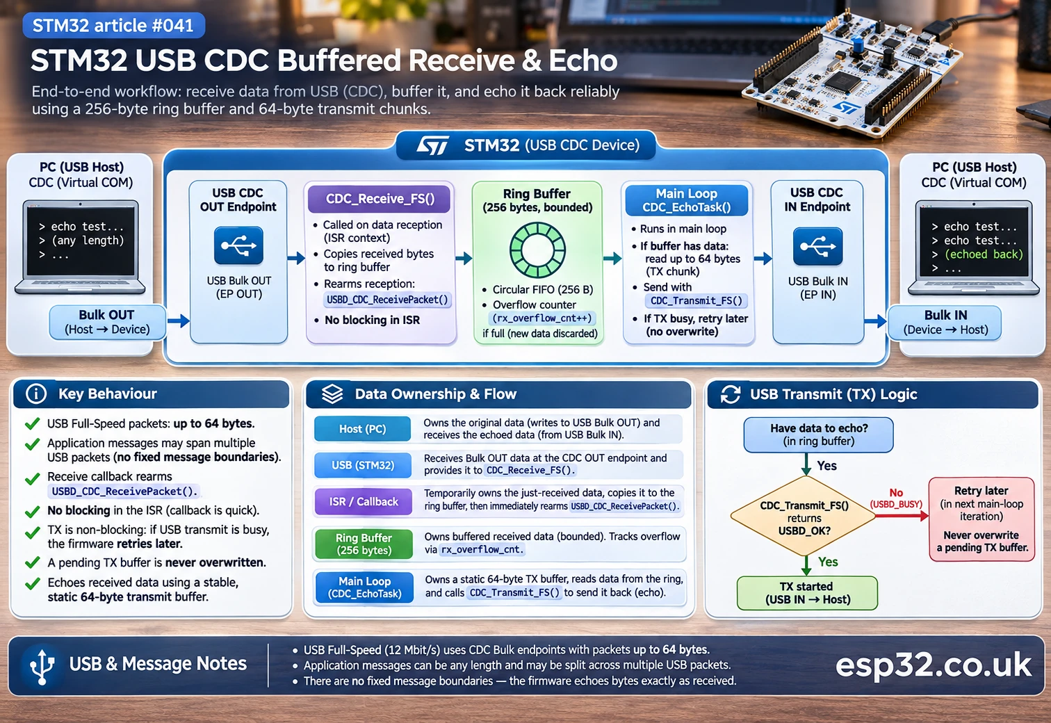
For a small educational application, use a single-producer/single-consumer 256-byte RX FIFO. The USB receive callback copies received bytes into the FIFO and promptly rearms the USB OUT endpoint. The main loop pulls the next chunk, submits it for echo, and keeps the TX buffer unchanged until the previous transfer has finished. This design is more reliable than calling CDC_Transmit_FS(Buf, *Len) unconditionally from the receive callback.
In USB_DEVICE/App/usbd_cdc_if.c, keep the generated includes and middleware callback table. Place the following near the other user declarations (and inside a preserved USER CODE section), with usbd_cdc.h available through the generated headers:
#define CDC_RX_FIFO_SIZE 256U
#define CDC_TX_CHUNK_SIZE 64U

static uint8_t cdc_rx_fifo[CDC_RX_FIFO_SIZE];
static volatile uint16_t cdc_rx_head = 0U; /* Written in USB RX context */
static volatile uint16_t cdc_rx_tail = 0U; /* Written in foreground */
static volatile uint32_t cdc_rx_dropped = 0U;

static uint8_t cdc_tx_chunk[CDC_TX_CHUNK_SIZE];
static uint8_t cdc_tx_inflight = 0U;

static void CDC_PushRxByte(uint8_t value)
{
    uint16_t next = (uint16_t)((cdc_rx_head + 1U) % CDC_RX_FIFO_SIZE);
    if (next == cdc_rx_tail)
    {
        cdc_rx_dropped++;
        return;
    }

    cdc_rx_fifo[cdc_rx_head] = value;
    cdc_rx_head = next;
}
Replace only the USER CODE region in the generated CDC_Receive_FS() with the following logic, keeping the generator’s function signature and its original return structure. A typical F1 USB device class uses hUsbDeviceFS:
/* Inside generated static int8_t CDC_Receive_FS(uint8_t *Buf,
 *                                               uint32_t *Len) */
for (uint32_t i = 0U; i < *Len; ++i)
{
    CDC_PushRxByte(Buf[i]);
}

USBD_CDC_SetRxBuffer(&hUsbDeviceFS, Buf);
(void)USBD_CDC_ReceivePacket(&hUsbDeviceFS);
return (USBD_OK);
This handler does only short, bounded work. USBD_CDC_ReceivePacket() rearms the OUT endpoint for additional host data. Do not leave the callback waiting for the PC terminal or repeatedly calling a busy transmitter. Because the ring buffer is finite, bursts faster than the foreground consumes them can still cause overflow; cdc_rx_dropped records that condition for debugging. If you need guaranteed delivery, add flow control at the application protocol level or a larger properly designed queue.
Now add a small foreground function to the same file, declared in usbd_cdc_if.h inside a preserved USER CODE section as void CDC_EchoTask(void);. The implementation below checks whether a previous asynchronous transmission has finished before touching its static TX buffer again:
void CDC_EchoTask(void)
{
    USBD_CDC_HandleTypeDef *hcdc =
        (USBD_CDC_HandleTypeDef *)hUsbDeviceFS.pClassData;
    if (hUsbDeviceFS.dev_state != USBD_STATE_CONFIGURED || hcdc == NULL)
    {
        return; /* PC not fully connected/enumerated */
    }

    if (cdc_tx_inflight != 0U)
    {
        if (hcdc->TxState != 0U)
        {
            return; /* Previous buffer still belongs to USB driver */
        }
        cdc_tx_inflight = 0U;
    }

    uint16_t cursor = cdc_rx_tail;
    uint16_t count = 0U;
    while (cursor != cdc_rx_head && count < CDC_TX_CHUNK_SIZE)
    {
        cdc_tx_chunk[count++] = cdc_rx_fifo[cursor];
        cursor = (uint16_t)((cursor + 1U) % CDC_RX_FIFO_SIZE);
    }

    if (count > 0U &&
        CDC_Transmit_FS(cdc_tx_chunk, count) == USBD_OK)
    {
        cdc_rx_tail = cursor;
        cdc_tx_inflight = 1U;
    }
}
Call CDC_EchoTask() repeatedly from the generated while (1) loop in main.c, after USB initialization. Keep the function call in a preserved USER CODE section. For this second demonstration, remove the periodic greeting loop so that both examples do not compete for the same CDC transmit endpoint. The echo project requires no deliberate HAL_Delay() because a long foreground delay can cause the finite RX queue to fill.
This is an educational, bare-metal, single-producer/single-consumer example. It assumes the generated F1 USB stack and class handler use the classic hUsbDeviceFS.pClassData and TxState fields. If your package or middleware revision changes those names, adapt to its documented transfer-completion API. A production logger should include explicit queue ownership, disconnect/reconnect handling, USB reset recovery and an application protocol that defines message boundaries.
Why USB CDC_Transmit_FS sometimes returns USBD_BUSY
USB data transfer is asynchronous. Calling CDC_Transmit_FS() normally asks the middleware to schedule an IN transfer; it does not mean the host has already received every byte. While a transfer is active, the USB CDC class may set TxState and reject a new transfer with USBD_BUSY. An example that writes a message inside a tight loop and ignores the return value may appear to work at low load but lose entire messages later.
The first rule is to keep TX data valid until completion. A static string or persistent buffer works; a short-lived stack array from a function that returns immediately is unsafe if the middleware still points to it. The second rule is to serialize transmit requests and decide what happens on busy: retry later, queue data, or explicitly drop low-priority log messages. The third is to distinguish CDC transmit acceptance from actual end-to-end delivery by the PC application.
The FIFO example illustrates a simple queue but does not impose flow control on the USB host. Under a sustained write stream, 256 bytes is tiny. For robust command communication, terminate commands with delimiters or length prefixes, parse frames in the foreground, acknowledge reception at application level where needed, and count overflows. If the host writes binary payloads, do not treat a zero byte as the end of a string. Use Len and explicit buffer lengths, never rely on strlen() for arbitrary received USB data.
The USB full-speed bulk endpoint maximum packet size is typically 64 bytes for CDC data on this stack. That does not restrict your application message to 64 bytes, nor does it guarantee exactly one host message per USB packet. The middleware fragments and reassembles transfers according to USB rules. The 64-byte TX staging in our example is a deliberate convenient choice, not a universal protocol frame size.
Control-line state, opening the terminal and connection timing
CDC ACM hosts may assert DTR or change line-coding parameters when a terminal opens the virtual COM port. A USB device can finish enumeration before a terminal is ready, which explains why a greeting sent only once during startup may never be seen. Repeating a short greeting every second makes a first demonstration easier to observe.
Applications that need reliable session startup can track CDC control requests such as CDC_SET_CONTROL_LINE_STATE, set a connected flag based on the host’s control-line state, and wait until the host application declares itself ready. Avoid making this a universal assumption: different terminals and operating systems may open CDC ports with different control-line behaviour. The example above intentionally does not rely on DTR for basic echo operation.
If the host unplugs and reconnects, the USB class and device state can be reset. Production firmware should explicitly clear or reinitialize its transport state, discard stale partial commands, and make sure pending TX buffers are not treated as successfully delivered after disconnection. A robust product also needs a well-defined way to distinguish USB CDC from a bootloader interface that may temporarily enumerate with another identity.
Verify the setup with a host-side Python test
A terminal is sufficient for manual typing and echo. For a repeatable host check, Python with pyserial can open the detected CDC port, write an ASCII payload and read the echoed bytes. The script below uses a port selected by the user, not an invented fixed COM number:
import serial

port = input("CDC port (e.g. COM7 or /dev/ttyACM0): ").strip()
message = b"esp32.co.uk/ USB CDC echo test\r\n"

with serial.Serial(port, baudrate=115200, timeout=2) as ser:
    ser.reset_input_buffer()
    ser.write(message)
    ser.flush()
    received = ser.read(len(message))

print("Sent:     ", repr(message))
print("Received: ", repr(received))
print("Match:    ", received == message)
For the echo firmware, expected output is Match: True if the host and USB queues deliver the complete payload within the timeout. pyserial must be installed separately with python -m pip install pyserial. This test is not suitable for the periodic-greeting-only firmware, because that example does not echo what the PC sends. If a few bytes are missing, inspect timing, driver state, buffer overflow and conflicting terminal processes before changing the USB crystal configuration.
If you want to test multiple messages, introduce a delimiter and a request/response scheme instead of assuming an arbitrary USB read contains exactly one message. The host can return fewer bytes than requested even with a valid device and correct firmware; robust host code loops until the expected length or an explicit timeout.
How CDC differs from factory DFU and ST-LINK programming
A conventional STM32F103C8 does not provide native USB DFU through its factory system-memory bootloader. Setting BOOT0 high and pressing reset does not turn this particular MCU into a USB DFU device. Use SWD via ST-LINK or the F103 ROM USART1 loader for initial firmware installation. A third-party USB bootloader can be installed into flash, but it occupies memory and has its own descriptors, toolchain and recovery behaviour.
| Task | Reliable F103C8 method | Common misconception |
|---|---|---|
| First firmware programming | ST-LINK SWD PA13/PA14 | Micro-USB automatically uploads code |
| Factory ROM alternate upload | USART1 PA9/PA10, correct boot pins | BOOT0 automatically enables USB DFU |
| Application terminal output | USB CDC firmware over PA11/PA12 | ST-LINK COM port necessarily equals target native USB |
| Recover broken USB CDC build | SWD independent of CDC | Reinstall host driver to repair absent firmware |
| Reprogram over USB without SWD | Optional installed custom USB bootloader | Native CDC class itself is necessarily a bootloader |
ST-LINK’s own USB connection carries debugger traffic and, on some newer probes or Nucleo boards, a separate virtual COM bridge to a hardware UART. That debugger bridge is not the Blue Pill’s native USB CDC interface. Our STM32CubeProgrammer flashing guide explains the different programming paths, while the Blue Pill USB troubleshooting guide concentrates on enumeration faults.
A structured troubleshooting table
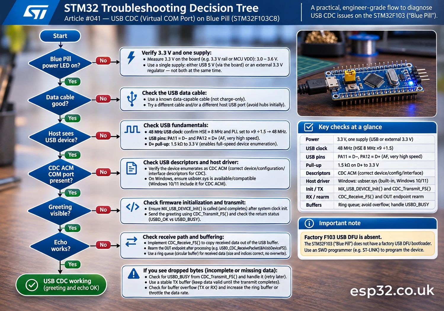
When USB fails, find the layer that fails before editing files. A serial port visible on the host and a responsive echo task prove different things from an illuminated power LED.
| Symptom | Most likely layer | Action to take |
|---|---|---|
| Board powers but host detects nothing | Cable, D+ attach, USB firmware, clock | Verify USB data cable, HSE/48 MHz, CDC initialization, pull-up |
| Unknown USB device / descriptor failed | Electrical signaling or USB initialization | Check PA11/PA12, pull-up, HSE startup, 3.3 V stability, descriptors |
| USB device visible, no COM port | Incorrect USB class or host CDC binding | Inspect descriptors/VID:PID and built-in CDC driver, not random drivers |
| COM port visible, no greeting | Application startup or terminal choice | Check firmware image, main loop, new port number, send timing |
| Greeting works, host writes are ignored | Receive endpoint/callback | Check CDC_Receive_FS, rearm call and host terminal local echo |
| Echo works only for short writes | FIFO overflow or busy handling | Check cdc_rx_dropped, TX buffer lifetime, throughput and queue size |
| CDC_Transmit_FS repeatedly BUSY | Pending IN transfer / endpoint state | Confirm configured state, completion handling and avoid conflicting writers |
| USB works, then drops on sensor activation | Power, noise or blocking code | Check regulator voltage, IRQ starvation, timing and attached hardware |
| DFU tool never sees target | F103C8 ROM lacks native USB DFU | Use SWD or factory USART1 ROM loader |
| MCU works through SWD but native USB never detects | USB-specific hardware/firmware | Inspect oscillator, PA11/PA12 routing, resistor and connector solder |
The COM port never appears
First test with a known data-capable cable, another host port and the simplest firmware. Check the host’s USB device tree. If there is no attachment event, Windows driver replacement is not the sensible first action. Check board power, executable firmware, the D+ pull-up and USB clock. If the host reports an unrecognized device, it has detected at least some electrical activity, so USB signalling, descriptor responses, clock stability and firmware initialization become likely areas.
On some Blue Pill clones, the D+ pull-up is incorrectly fitted. Measure the actual circuit before modifying the board; the reference design should provide about 1.5 kΩ to 3.3 V. F103 clones and dev boards have varying silkscreen labels, so R10 is a clue, not a universal resistor reference. Don’t attempt live resistance measurements on an energized USB circuit. Disconnect power and follow safe measurement practices.
The COM port appears but nothing is transmitted
Make sure the greeting example actually calls CDC_Transmit_FS() after USB initialization, and that the MCU was resumed after a debugger halted it at main(). Confirm that the serial port being opened belongs to the STM32 CDC interface rather than ST-LINK VCP or an old USB-UART converter. If the program sends text only once before a terminal opens, the text may have been missed. The periodic example avoids that by sending repeatedly.
A virtual COM port number can change when descriptors, USB devices or bootloader states change. On Linux, check whether the correct device is /dev/ttyACM*, not a stale /dev/ttyUSB*; on macOS, recheck the relevant cu.usbmodem device. The terminal may also require DTR to be asserted before showing useful interaction, depending on its settings and your application.
Transmit reports BUSY and characters disappear
That normally means the program is submitting another IN transfer before the previous one completes, or USB is not in the configured device state. Use persistent TX buffers and submit again only when the class is ready. Avoid continuously writing to the same buffer while it is owned by the USB driver. Do not attempt blocking delays inside CDC_Receive_FS(); that can stall USB handling and create secondary faults.
USB becomes unreliable with other peripherals enabled
Check PA11/PA12 conflicts, particularly if another peripheral or GPIO function was configured on those pins. Some F103 designs use PA11/PA12 for default CAN routing; USB and CAN cannot simultaneously claim the same pins. If CAN is required too, check supported alternate remapping and the board schematic, and remember that CAN needs an external transceiver. On a small board, adding sensors or displays can also overload the 3.3 V rail. Return to the bare minimum USB CDC project before blaming Windows.
USB is stable on one computer and unstable on another
A marginal pull-up, data cable, connector joint or signal integrity issue may pass with one host but fail with another. Compare direct ports, check the USB cable and inspect the power and USB routing. USB full-speed requires appropriate signal routing and a reasonably stable clock; a firmware workaround cannot compensate reliably for every physical-board problem. ST’s AN4879 is the hardware reference for proper pull-up and layout rules.
Performance, packet size and memory budget
The F103C8 is a small MCU with 20 KB SRAM and 64 KB specified flash. USB middleware, class state, endpoint buffers, the HAL and your application share those resources. The 256-byte ring buffer, 64-byte TX staging buffer and generated USB FS packet RAM are adequate for a demonstration but not generous capacity for sustained data logging. Measure the actual map file and stack use rather than assuming that a 64-byte USB packet implies a 64-byte application queue.
The bus is USB full-speed (12 Mbit/s signaling), but the maximum theoretical bus bit rate is not the application throughput. Control transactions, framing, host scheduling, firmware overhead and buffering lower practical data delivery. For modest terminal output, prioritize correctness and responsiveness. For serious streaming, test sustained transfers with known host software, count dropped data, optimize processing and choose ring buffers sized for worst-case application latency.
When scaling to a data acquisition application, keep the ADC and timer sampling paths independent from slow USB transmit behavior. An ADC DMA buffer can be filled periodically, with complete blocks transferred to a separate USB queue in the foreground. Never block the ADC interrupt while waiting for USB TxState. The buffer ownership and latency calculations matter more than simply calling the CDC API frequently.
Production considerations before deploying USB CDC
The examples are suitable starting points, not a finished commercial communications stack. A robust device should define stable device descriptors, manufacturer/product strings and legitimate USB VID/PID usage, handle disconnects, recover from USB reset, protect its RX queue from overflow, parse command frames safely and avoid reliance on a specific COM number. Choose the actual CDC class/interface combination that matches the host operating systems you intend to support.
Do not ship unlicensed or borrowed USB vendor IDs. For a custom product, use an appropriately assigned VID/PID or a legitimate arrangement through the hardware/platform vendor. Descriptors copied from a random tutorial may create collisions or confusing host driver behavior. Also distinguish Windows’ standard CDC ACM driver support from other USB classes that may require different drivers.
If the device accepts privileged commands over CDC, decide what happens if the PC sends malformed or excessive input. Bound every received length, avoid unchecked sprintf or strcpy, keep calibration and persistent writes behind explicit validation, and consider authentication for commands that control actuators or security-sensitive state. USB CDC is a transport, not a security boundary.
For reliability, consider adding a watchdog only after your firmware handles resets and USB reconnection cleanly. A watchdog-reset loop can mask a power or clock fault and repeatedly force USB disconnects. Keep SWD available in the prototype for recovery; disabling debug pins too early turns routine firmware mistakes into avoidable restoration work.
Frequently asked questions
Does the Blue Pill need an external USB-to-serial adapter for USB CDC?
No. The STM32F103C8 has a native USB full-speed device peripheral on PA11 and PA12. With correctly configured firmware and hardware it can enumerate directly as CDC ACM through the Micro-USB connector. A USB-UART adapter is an alternative for USART communication, not a prerequisite for native USB CDC.
Can I flash the F103C8 through its Micro-USB port using STM32CubeProgrammer USB DFU?
Not on a standard blank F103C8 through its factory bootloader. Factory ROM support is different from the user application’s USB controller. Use SWD or USART1 to install firmware. Custom bootloaders can later provide a USB upload path if installed deliberately.
Why is USB 48 MHz necessary if the CPU only runs at 72 MHz?
The USB controller has a separate timing requirement: full-speed data signaling needs an accurate 48 MHz clock derived from a suitable oscillator/PLL arrangement. With a verified 8 MHz HSE crystal, multiplying by nine and dividing by 1.5 gives 48 MHz. The CPU’s ability to blink an LED does not prove the USB clock is correct.
Is CDC_Transmit_FS() a blocking UART write?
No. It submits USB IN data to the device middleware, which transfers it asynchronously. It can return BUSY if another transfer is still pending. Keep the buffer stable until completion and arrange application queuing for sustained data streams.
Why does opening the virtual COM port at a different baud rate still work?
Because a native CDC virtual serial port uses USB packets rather than a UART bitstream at a selected hardware baud. The baud setting is communicated as CDC line-coding metadata; firmware may apply it to a separate UART bridge, but a direct CDC application does not have to.
Why do I see a serial device but no echo?
Check whether you flashed the greeting-only demo or the echo demo, whether CDC_Receive_FS() rearms the OUT endpoint, and whether CDC_EchoTask() is called from the main loop. Also confirm the terminal’s local echo setting and make sure another program has not opened the same port.
Can the same Blue Pill use USB CDC and bxCAN simultaneously?
Potentially, with supported remapping and a board layout that exposes suitable alternative CAN signals, but not if both peripherals attempt to use the same default PA11/PA12 pins. The exact combination requires reference-manual AFIO verification and an external CAN transceiver. For an uncomplicated first USB project, leave CAN disabled.
Does USB CDC guarantee one receive callback for every command?
No. USB is packet-based; software writes and reads are not necessarily preserved as application message boundaries. Use delimiters or explicit frame lengths in your protocol and handle partial data correctly.
Practical checklist before publishing your firmware
- Verify actual MCU marking and board revision, its 8 MHz HSE clock, and regulated 3.3 V supply.
- Use a known-good Micro-USB data cable and avoid competing external power sources.
- Configure USB DM PA11 and DP PA12 without other peripheral pin conflicts.
- Make USBCLK 48 MHz from a valid stable oscillator and prescaler configuration.
- Generate USB Device FS and the CDC class using a compatible STM32CubeF1 package.
- Keep SWD PA13/PA14 enabled for recovery and flash the first build via ST-LINK.
- Confirm host enumeration before troubleshooting terminal baud or application parsing.
- Use static/persistent TX buffers, respect
USBD_BUSY, and rearm the receive endpoint. - Bound RX queues and make message framing explicit for longer or binary messages.
- Verify behavior on the specific host operating systems you plan to support.
Conclusion
A Blue Pill native virtual COM port is a useful building block once its layers are understood: electrical USB data on PA11/PA12, a genuine 48 MHz USB clock, the USB Device CDC middleware, and an application that correctly manages asynchronous receive and transmit buffers. Programming the F103C8 over ST-LINK first avoids dependence on a factory USB bootloader that this chip does not have. A visible COM port proves enumeration; stable two-way echo demonstrates that your application and endpoint state are actually working.
This esp32.co.uk/ guide is designed to be used alongside our STM32 GPIO, UART and USB troubleshooting articles, not as a substitute for the datasheet or board-specific schematic. Once the CDC echo works consistently, the same transport can support configuration commands, sensor streaming and PC logging, provided you add framing, flow control and error handling that match the application’s demands.
References and further reading
- ST AN4879: USB hardware and PCB guidelines — device pull-up and reliable USB electrical design.
- ST RM0008: STM32F1 reference manual — RCC and USB device peripheral.
- ST UM1734: STM32Cube USB Device library — USB CDC class interface and transfer API.
- ST USB Device middleware on GitHub — source for CDC transport and TxState behavior.
- Microsoft USB CDC ACM driver documentation — built-in Windows usbser.sys support.
- esp32.co.uk/ Blue Pill USB troubleshooting — diagnosing USB connection failures.