Quick Summary (TL;DR)
RS485, CAN and Ethernet are not interchangeable solar-and-battery communication methods. RS485 is a differential electrical interface frequently used for Modbus RTU meters and inverter telemetry; CAN is a differential bus often used by managed lithium batteries and by some solar controllers; Ethernet is a networking technology that can carry Modbus TCP, MQTT, JSON APIs or proprietary services. A socket that looks like an RJ45 Ethernet port can instead carry CAN, RS485 or a manufacturer’s own signals. Matching the plug is not evidence of compatibility.
Our recommendation: for Home Assistant or ESP32AliExpress price monitoring, start with a manufacturer-supported local API or a supported gateway. Use an approved RS485/Modbus adapter only where the exact device’s documentation expressly permits third-party reading. Treat the battery-to-inverter BMS communications link as a protected operational interface, not a place to experiment with generic CAN sniffers, fabricated adapters or unapproved command injection. An incompatible BMS link can interrupt charge/discharge limits or cause the battery to disconnect.
If buying hardware, ask for the precise inverter and battery model and firmware, a copy of the supported interface specification, whether the port is already occupied, and who will support the resulting integration. A gateway with an existing Home Assistant integration is often better value than a cheaper adapter that leaves you reverse-engineering undocumented frames.
The communication map: from battery to dashboard
Solar systems contain several different communication paths. Confusing them is the main reason that a seemingly straightforward monitoring project turns into a frustrating or unsafe installation. The battery BMS may tell a hybrid inverter what charging voltage, current and discharge limit are permitted. The inverter may ask an external electricity meterAliExpress price how much power is crossing the grid connection. A local gateway can collect equipment telemetry and offer it to a home network. Home Assistant then reads the gateway, usually without needing to touch the original BMS or power-control bus.
For example, a supported lithium battery could communicate with a Victron GX device over a dedicated BMS-CAN profile, while the GX device exposes system measurements to Home Assistant via its network. In that architecture, the safety-critical battery link stays intact, and the automation platform receives a separate interface intended for third-party access. Victron explicitly documents separate VE.Can and BMS-Can applications and warns against sharing incompatible buses. See the GX connection manual and the CAN-bus BMS cable guide.
| Link in the installation | Common technology | Primary purpose | Sensible Home Assistant approach |
|---|---|---|---|
| Grid meter to hybrid inverter | RS485 carrying Modbus RTU or vendor protocol | Import/export data used for export limiting and battery dispatch | Read through the inverter/gateway, or an approved separate read-only interface |
| Battery BMS to hybrid inverter or gateway | CAN, sometimes RS485 or proprietary protocol | Charge and discharge limits, state, alarms and interlocks | Use supported gateway telemetry; do not insert experimental adapters |
| Solar charger to monitoring gateway | VE.Direct, VE.Can or proprietary serial | Charging measurements and device state | Manufacturer-approved GX/monitoring connection |
| Inverter or gateway to router | Ethernet or Wi-Fi | Network access to API, MQTT, Modbus TCP or cloud agent | Official local integration where available |
| External DIN-rail meter to ESP32AliExpress price | Usually RS485/Modbus RTU | Independent power and cumulative energy readings | Isolated, properly specified RS485 adapter; read-only configuration |
| Vendor cloud to mobile app | Internet HTTPS/MQTT or vendor protocol | Remote history, alarms and service | Accept latency/availability and privacy implications |
An architectural diagram from an installer should identify each link separately rather than drawing a single line labelled “communication”. Record the cable type, port role, protocol, firmware and support responsibility for every link.
RS485: an electrical interface, not a complete protocol
RS485 specifies an electrical signalling method designed for differential, often multidrop serial networks. It does not define which register means solar output, how a device is addressed, or whether writing to that register changes a dangerous parameter. Modbus RTU is one common application protocol carried on RS485, but an RS485 port could instead use a proprietary frame format. Consequently, an “RS485 compatible” USB dongle is only the starting point of the compatibility discussion.
In an approved Modbus RTU implementation the client sends queries to a device address and receives register values. Documentation must establish baud rate, framing/parity, device address, register map, signedness, scaling, byte and word order, and whether the registers are read-only. Two devices can share RS485 wiring conventions yet have entirely different register meanings. Manufacturer firmware revisions can change their capabilities too.
Practical electrical points to check with the installer include line topology, termination at the specified ends, required biasing, isolation, cable screening, surge environment and proper separation from mains conductors. These requirements are site- and product-specific: do not add termination resistors or bridge shields by guesswork. A reversed differential pair, duplicated unit address or incorrectly configured baud rate can result in timeouts or nonsense readings. On installations with multiple clients, avoid adding a second polling master to a meter’s operational link unless the vendor explicitly permits it.
Solis has model-specific RS485 port testing guidance; note its distinction between port formats on S5, S6 and other inverter families. The fact that several models say “RS485” does not give them identical pin-outs or guarantee that a third-party monitor can share the port.
| RS485 question | Why it matters | Evidence to request |
|---|---|---|
| Is the port Modbus RTU or proprietary? | The physical bus alone is not an API | Exact device interface manual |
| Is it allocated to a revenue, import/export or control meter? | Interrupting it could affect export controls or dispatch | Manufacturer topology diagram |
| Is third-party polling supported? | Extra masters can conflict on serial lines | Published integration instructions |
| What settings and register revision apply? | Invalid scaling and register offsets produce misleading power | Current register list and firmware note |
| Is galvanic isolation required? | Earthing differences and surges can damage equipment | Approved adapter specification |
| Who verifies termination and routing? | Wiring faults mimic software faults | Commissioning and installer records |
RS485-to-Ethernet is a bridge, not a universal solution
An RS485-to-Ethernet gateway can transport serial data across the LAN or expose a Modbus TCP service. But a generic serial server often simply tunnels bytes; it cannot invent a Modbus register map or translate proprietary battery frames into standard measurements. Likewise, Modbus RTU over TCP and Modbus TCP are not necessarily the same mode. Check precisely what the gateway supports, how many clients are allowed and whether it is approved for the device and topology.
For an ESP32AliExpress price project, use a properly engineered RS485 transceiverAliExpress price or isolated gateway, the manufacturer-published read registers, and read-only integration logic. ESPHome’s Modbus Controller documentation explains how an ESPHome node can act as a Modbus client. The component is capable of writing as well as reading; restricting a monitoring project to configured sensors is a deliberate safety choice. Do not transplant register values from an unrelated inverter just because the configuration syntax appears to work.
CAN and BMS-CAN: same bus family does not mean interchangeable systems
CAN, short for Controller Area Network, is a message-oriented differential bus used in vehicles, industrial equipment, energy systems and embedded products. It supports arbitration and robust error handling. In energy storage, CAN may carry managed-battery data the inverter needs to operate within the battery’s permitted charge/discharge envelope. An inverter that loses valid BMS messages may stop charging, stop discharging, alarm or shut down according to its approved safety design.
The distinction between VE.Can, BMS-Can, third-party CAN profiles and vendor-specific battery communications matters. Devices need agreement on bit rate, framing, application messages, IDs and expected behaviour, not merely the same CAN-H and CAN-L wires. Victron’s documentation distinguishes VE.Can networks from BMS-CAN and notes different profiles and terminators; it specifically says these buses must not simply be combined. The correct port and profile depend on the exact GX model and attached products, as documented in the GX connectivity manual.
For a concrete example, Victron provides different type A and type B VE.Can-to-CAN-bus BMS cables for different managed-battery models. Even batteries from the same broad brand family can use different approved cable types. The official cable compatibility list is more authoritative than a marketplace listing claiming “Pylontech/Victron compatible”. The Victron–Pylontech integration page also calls out bus profiles, terminators and the importance of the battery appearing correctly on the GX display.
| CAN-related label | What it generally describes | What it does not prove |
|---|---|---|
| CAN-H and CAN-L | Differential signal pair | Correct voltage, grounds, pin-out or protocol |
| RJ45 CAN connector | One form factor used by some devices | Ethernet compatibility or standard RJ45 pin assignments |
| VE.Can | Victron CAN-based device networking | Automatic interchangeability with every third-party battery |
| BMS-Can / CAN-bus BMS | Managed-battery communication profile | Compatibility with all battery vendors or firmware |
| “CAN compatible” USB adapter | Interface for certain frames and bit rates | Permission to attach to the live battery control bus |
| CAN-to-Ethernet gateway | Transport or application translation, depending on design | Approved battery management or preservation of interlocks |
Why “sniffing” a BMS link is not a beginner’s monitoring method
Passive observation of communication may sound harmless, but attaching an unknown transceiver can change loading, grounding or termination, and a misconfigured tool can transmit unwanted frames. Reverse-engineering a live battery link also risks making control assumptions that fail under temperature limits, fault states or different firmware. We do not recommend DIY tapping, spoofing BMS messages or bypassing the manufacturer’s supported battery-inverter pairing. For telemetry, use a supported GX or vendor gateway, a manufacturer-documented secondary port, or an independent properly installed battery monitor.
If an installer insists that an interface is supported, request the exact document identifying the two product models, firmware ranges, cable assembly, CAN profile, termination and commissioned behaviour. If no such evidence exists, it should be treated as an experimental integration rather than a supported purchase.
Ethernet and Wi-Fi: what the port actually makes possible
A network socket or Wi-Fi connection is attractive for Home Assistant because it often avoids new signal wiring between an inverter and your server. However, Ethernet only describes how data travels on a network. The accessible service may be Modbus TCP, a local JSON/REST API, MQTT, a vendor agent that relays data to the cloud, or nothing available to third-party clients.
Fronius is a useful positive example: its documented Solar API returns JSON readings from supported inverter/data-manager combinations. Victron GX offers both a supported local MQTT-based Home Assistant integration and documented Modbus TCP. Conversely, a manufacturer-provided Wi-Fi dongle may be designed primarily for cloud upload; a LAN IP address does not promise a supported local API. Always check the exact dongle and firmware, not merely the inverter brand.
| Network integration | Local operation when internet fails? | Setup and ongoing trade-offs | When to choose |
|---|---|---|---|
| Official Home Assistant integration using local API | Usually yes, if device and LAN remain powered | Best-maintained entity mapping; capabilities vary | First choice for supported hardware |
| Documented local MQTT gateway | Yes, if broker/network paths remain reachable | Authentication, discovery, event rates and entity permissions | Existing supported GX or vendor gateway |
| Documented Modbus TCP | Yes | Unit IDs, register mapping, scaling and write security | Integrators who need exact measurements |
| Manufacturer REST/JSON endpoint | Yes where vendor provides it | Version/endpoint support and polling limits | Read-only device dashboards |
| Vendor cloud integration | No, typically internet dependent | Account, outage delays, privacy, subscriptions | Remote-only equipment where no local option exists |
| Community or reverse-engineered protocol | Sometimes | Breakage after firmware changes; limited support | Last resort for non-critical telemetry |
Security matters: isolate energy equipment from guest and untrusted networks, use the device’s supported authentication/TLS modes where provided, keep firmware current through approved update procedures, and do not expose Modbus TCP or unprotected MQTT directly to the internet. A dedicated VLAN may reduce exposure but does not automatically secure writable control endpoints. Record who is allowed to change inverter parameters and who can only observe readings.
Proprietary buses: VE.Direct, VE.Bus, battery cables and vendor dongles
Not everything in a solar cabinet fits neatly into Modbus or CAN. Victron VE.Direct is a point-to-point device interface used by several chargers and battery monitors; VE.Bus is a separate proprietary system for supported inverter/chargers and associated control equipment. Victron’s data communications whitepaper explains the distinction between these interfaces and network-oriented Modbus TCP. Neither should be assumed to be an ordinary RS485 Modbus connection just because a serial-looking cable is present.
Other manufacturers have bespoke logger connectors or installer-service ports. Some battery units offer similarly shaped “LINK”, “COM”, “RS485” and “CAN” ports, where only one is approved for communication with a specific inverter. On top of that, a communications harness may carry an enable signal or auxiliary power. Solis’s battery port guidance illustrates the need for model-specific connection instructions. A cable supplier’s generic product title is not sufficient evidence that these interfaces can be connected safely.
The most useful purchasing distinction is between a manufacturer-approved adapter that makes an established device available to the supported gateway and a generic protocol converter with no vendor agreement. The latter may still be useful for independent laboratory work, but it should not be sold to homeowners as a plug-and-play safety-critical BMS accessory.
What about SunSpec Modbus?
SunSpec publishes interoperable information models for solar inverters, meters and energy storage. SunSpec Modbus uses standardised model structures on top of the Modbus protocol, and it is a stronger starting point than guessing proprietary register meanings. But a product being labelled “Modbus” does not make it SunSpec compliant; nor does SunSpec compliance imply every optional model or writable function is implemented. Manufacturers can also apply model-specific variants or limit functionality in particular firmware.
The SunSpec specification catalogue describes energy-related information models and the distinction between open standards and conformance testing. The SunSpec Modbus programme explains device certification. Ask which SunSpec models and register versions an inverter actually supports, and whether the interface is enabled for the owner’s configuration. Read-only measurements are adequate for most dashboards. Writing settings for export limits, voltage response or battery charge behaviour belongs to an installer-led, approved control design.
Which hardware should you actually buy?
Treat the communication device as part of a whole system rather than a standalone bargain. A cheap RS485 stick can make sense for a spare independent energy meter; it is a poor substitute for a supported gateway handling a lithium battery and hybrid inverter. Likewise, paying for a cloud dongle when your system already has a documented local interface may add an unnecessary recurring dependency.
| Purchase option | Appropriate use | Check before ordering | Common missed costs |
|---|---|---|---|
| Manufacturer GX/monitoring gateway | Consolidated inverter, battery and meter telemetry | Device and firmware compatibility, physical ports, supported local integrations | Gateway power, approved cables, installation and network setup |
| Approved branded CAN/BMS cable | Exact battery-to-gateway pairing | Exact battery generation, cable type and bus profile | Installation time, terminators and commissioning |
| Isolated RS485-to-USB interface | Independent supported Modbus RTU meter | Isolation, supply, host OS, serial settings and port availability | Industrial cable, enclosure and electrician labour |
| Industrial RS485-to-Ethernet gateway | Remote approved serial telemetry | True Modbus TCP conversion versus transparent serial tunnel | Power supply, surge protection, IP configuration and maintenance |
| ESP32 plus isolated RS485 interface | Low-cost read-only monitoring for documented devices | Accurate register map, safe isolation and enclosure | Development, debugging, maintenance and replacements |
| Proprietary vendor Wi-Fi/LAN logger | Supported cloud or local logging | Exact hardware generation, local API and service access | Subscription, account dependency and future replacement |
Rather than claim a universal price, compare complete installed quotes. For example, a £25 adapter requiring £150 of troubleshooting and a return visit costs more than a £90 compatible device that the installer can commission in one visit. Those figures are illustrative arithmetic, not live market prices. Include cable assemblies, isolation, surge protection where specified, enclosure, gateway power, network reachability, training, labour and expected software support in the comparison. For critical operation, preserving the battery warranty and manufacturer support outweighs saving a small amount on a communications accessory.
A seven-question purchasing checklist
- Which exact make, model, hardware revision and firmware does the interface support?
- Is the connector Ethernet, RS485, CAN or proprietary — and what protocol runs across it?
- Is it a monitoring port or an operational link needed for battery management, meter feedback or export limitation?
- Does the manufacturer permit another reader or third-party client, and is a separate port available?
- Which documented local integration exposes the required metrics? Does it still work if broadband fails?
- What parts, power supplies, isolation, cable assemblies and labour are included in the installed quote?
- Who will support outages, firmware updates, security and warranty issues after installation?
Write those answers down before buying a dongle, RS485 interface or CAN cable. If the installer cannot confirm what a port does, request the manual rather than trying to find out by plugging in hardware.
A practical ESP32 and Home Assistant architecture
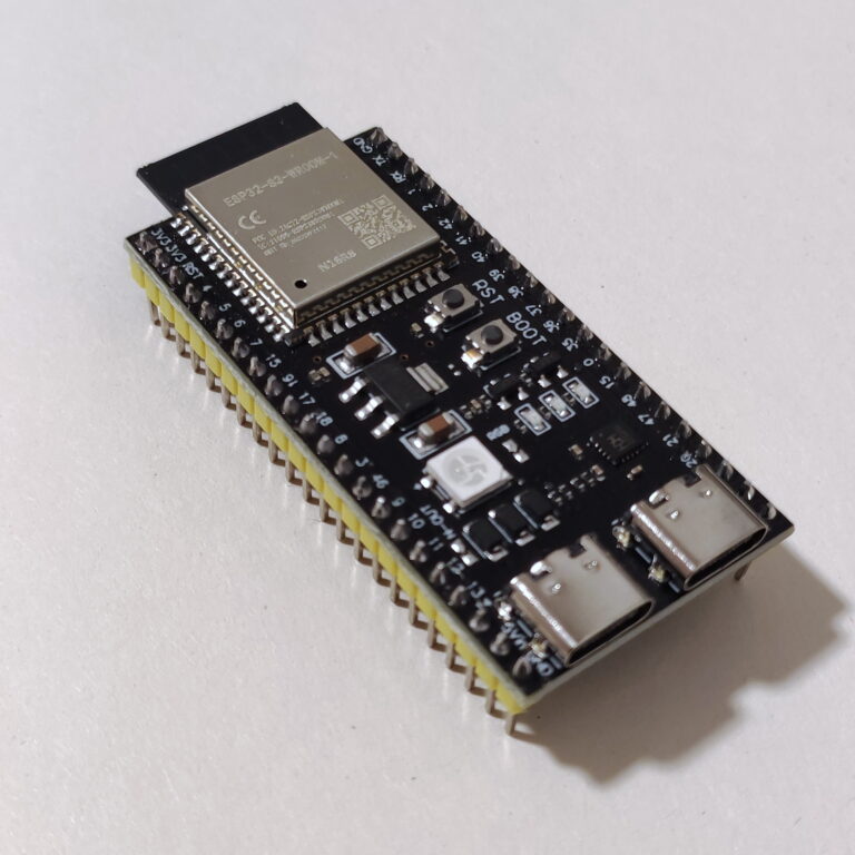
For a solar installation with an independent, manufacturer-documented Modbus RTU meter dedicated to monitoring, a read-only ESPHome ESP32 gateway can make sense. The installer provides an approved connection point and an appropriately rated, isolated RS485 interface. The ESP32 reads the meter registers through ESPHome and publishes them to Home Assistant; Home Assistant uses stable cumulative energy counters for the Energy dashboard. This design does not require the ESP32 to talk to a battery’s BMS CAN bus or change inverter set-points.
The following is a non-deployable structural example, intentionally omitting device-specific wiring, register addresses, UART pins and serial settings. Those values must come from the actual approved meter manual. The example shows component relationships, not an electrical installation recipe:
# Illustration only: not ready to flash or wire.
# Obtain the actual RS485 interface settings and read-only
# register map from the exact meter manufacturer's manual.
uart:
  id: meter_uart
  # tx_pin: ...
  # rx_pin: ...
  # baud_rate: ...

modbus:
  id: meter_bus
  uart_id: meter_uart

modbus_controller:
  - id: independent_meter
    address: 1  # Example slave address only
    modbus_id: meter_bus
    update_interval: 15s

# Add read-only sensors using the verified meter map.
# Never copy inverter/BMS write registers into this project.
Prefer the built-in or manufacturer-supported interface when it already exposes the same measurements. For a supported Victron GX system, the Home Assistant Victron GX integration can discover monitoring devices over local MQTT. If a specialist integrator prefers Modbus TCP, Victron’s GX Modbus TCP manual explains the per-device Unit-ID and register-map concepts. Those are two different paths to system telemetry; there is normally no advantage in exposing the operational BMS bus to the ESP32 too.
Useful follow-up guides already available on esp32.co.uk include the ESP32 SDM120/SDM630 Modbus energy meter walkthrough, the comparison of ESP32 energy monitoring methods and Victron Cerbo GX vs Raspberry Pi Venus OS. Those cover measurement choices and gateways without implying that an arbitrary battery CAN connection is safe to modify.
Troubleshooting: distinguish network, wiring and protocol problems
Troubleshoot in layers and start with observation rather than hardware changes. Record the inverter and battery’s normal status, installed interface type, firmware, logger lights and any vendor error message. If the energy system is producing faults, have the installer diagnose it using approved procedures; do not bypass the BMS or disconnect working operational meter links to “test” a Home Assistant sensor.
| Symptom | Likely investigation | Safer first action |
|---|---|---|
| Inverter works; Home Assistant entity unavailable | IP change, disabled API, credentials, MQTT service | Check device network status and official integration logs |
| RS485 adapter receives no valid values | Wrong register list, bus settings, serial-port ownership | Compare with exact documentation; do not rewire a live control meter |
| Values are negative, enormous or unstable | Wrong signedness, scale factor, endianness, phase mapping | Check approved register map and readings against manufacturer app |
| Battery is missing from gateway display | Unsupported battery profile, model mismatch, cable or firmware | Stop DIY modifications and consult certified installer |
| Loss of battery communication triggers fault | Operational BMS messages interrupted | Restore approved configuration through installer procedures |
| Cloud app works but local API does not | Cloud-only logger, firmware limitation or blocked LAN access | Verify actual local API support rather than assuming connectivity |
| Data stops when internet fails | Cloud dependency, remote DNS or broker placement | Consider supported local gateway; test offline before relying on it |
| Home Assistant energy totals disagree | Power/energy confusion, duplicated meters, sign convention | Compare cumulative import/export kWh at a clear metering boundary |
Test resilience without disturbing safety systems
For a monitoring installation, an internet-only outage test is useful: disconnect the home router’s external internet connection while leaving the LAN and energy equipment operating normally. Check whether sensor updates continue, whether cached values are mistaken for live values, and whether alerts and automations behave sensibly when telemetry disappears. This verifies the dashboard’s local independence without opening electrical cabinets or interfering with battery communication.
Use a data-quality check as well. A 3 kW reading held for a full hour represents roughly 3 kWh, but instantaneous inverter power is not itself an accumulated energy counter. Make sure your Home Assistant entities carry the correct units, measurement characteristics and device classes. Compare grid import/export cumulative totals with the billing meter and solar generation with the manufacturer’s monitored energy totals over a defined interval. The Home Assistant Energy documentation describes dashboard expectations.
Frequently asked questions
Is an RJ45 port on a hybrid inverter always Ethernet?
No. RJ45-style connectors are used for Ethernet, serial signalling, CAN communications and proprietary battery interfaces. Read the specific port label and wiring/function section of the exact product manual, not the socket’s appearance.
Can I connect an ESP32 CAN transceiver directly to a lithium battery BMS?
Not as a generic Home Assistant monitoring shortcut. A live battery-to-inverter bus can be safety-critical, and a transceiver’s presence does not establish compatibility or passive behaviour. Prefer approved gateway telemetry or a documented independent read-only monitor.
Is Modbus TCP more interoperable than Modbus RTU?
Both can be standardised and useful. TCP uses a network transport, while RTU commonly uses RS485 serial signalling. Interoperability depends on the implemented register map and permissions, not just transport. SunSpec models can improve consistency where the device actually supports them.
Can I use a network serial server to turn any RS485 inverter into Home Assistant sensors?
No. The server may merely tunnel serial frames. Without a supported command protocol, register list and permission to access the port, there is nothing reliable to decode. Some operational meters also cannot support an extra master safely.
Why does a battery work with one inverter but not another if both advertise CAN?
The devices may require different message profiles, bit rates, application states, supported battery lists, cable pin-outs and firmware. Contact the battery and inverter suppliers for the explicitly supported pairing; avoid generic “CAN-compatible” claims.
Will changing the data cable affect my system warranty?
Terms vary by manufacturer and jurisdiction, but unapproved modifications can create support and warranty disputes. Obtain written approval for any operational battery/inverter communication hardware changes and retain the commissioning record.
Which option is best for a new smart-home solar installation?
Ask the installer for a supported local gateway or native API from the start, with sufficient network access and future firmware support. Choose a battery/inverter pair based on verified compatibility and safety first. Add an ESP32 or independent meter only where it fills a real monitoring gap.
Final verdict
For most homes: keep the inverter-to-battery BMS connection manufacturer-managed, use a supported gateway to collect telemetry, and connect Home Assistant through a documented local network API. Pick RS485/Modbus for independent meters or explicitly supported inverter readings, CAN only within approved system combinations, and Ethernet/MQTT/JSON where official local integrations exist. There is no one universal “solar communications adapter”. The right choice is the one that fits the exact hardware, preserves protective functions and remains maintainable years later.
Official documentation and further reading
- Victron Energy — connecting products to GX devices
- Victron Energy — CAN-bus BMS cable compatibility
- Victron Energy — Pylontech battery compatibility
- Victron Energy — GX Modbus TCP manual
- Victron Energy — data communications whitepaper
- Home Assistant — Victron GX integration
- Home Assistant — Energy documentation
- ESPHome — Modbus Controller
- Fronius — Solar API open interfaces
- Solis — RS485 communication port guidance
- Solis — CAN communication troubleshooting
- SunSpec Alliance — interoperability specifications
Editorial note, October 2026: capabilities depend on exact product models, firmware revisions and manufacturer support policies. This is a selection and monitoring guide, not authorisation to alter live mains connections, disconnect operational BMS links or write inverter control registers. Engage an appropriately qualified installer for physical commissioning and any change to grid-connected or battery power hardware.