Quick Summary (TL;DR):
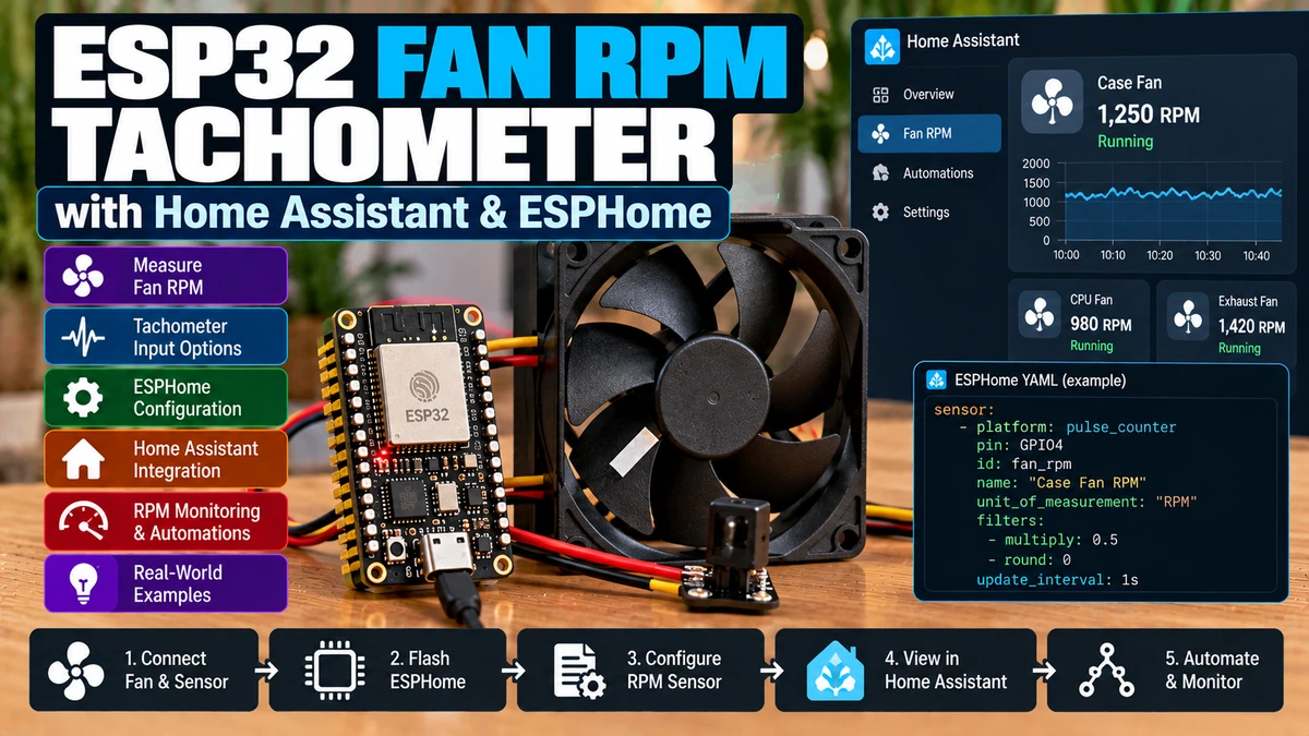
You can monitor the real speed of a 3-wire or 4-wire DC fan with an ESP32AliExpress price and ESPHome by reading the fan’s tachometer / RPM output. On standard PC-style fans, the tach wire is typically an open-collector output: the fan does not drive a HIGH voltage itself, so the ESP32AliExpress price should pull the tach line up to 3.3 V using the internal pull-up or, preferably for a robust installation, an external resistor. Do not pull the tach line up to the 12 V fan supply and connect it directly to an ESP32AliExpress price GPIO. Most 4-wire PWM fans produce two tach pulses per revolution; many 3-wire fans do too, but verify the exact fan datasheet before assuming it. ESPHome’s pulse_meter and pulse_counter sensors both report pulses per minute by default, so for a two-pulse-per-revolution fan RPM = pulses/min ÷ 2, which is simply a multiply: 0.5 filter. For fan RPM, pulse_meter is usually my first choice because it measures the time between pulses and gives smoother/higher-resolution results at low speeds. Set a realistic timeout so a stopped fan reaches 0 RPM promptly instead of waiting for the 5-minute default. Once RPM is in Home Assistant you can detect a stalled fan, verify that PWM speed commands actually change physical speed, alarm if commanded speed is non-zero but tach stays at zero, and track cooling-system health over time. A 2-wire fan has no separate tach wire, so you normally cannot read RPM without an internal FG/test point or an external sensor.
Materials You’ll Need
| Item | Why you need it |
|---|---|
| ESP32AliExpress price development board | Counts tach pulses and sends RPM to Home Assistant |
| 3-wire or 4-wire fan with tach output | Provides the RPM pulse signal |
| Correct fan power supplyAliExpress price | Usually 5 V, 12 V or 24 V depending on fan |
| External pull-up resistor | Pulls open-collector tach line to safe 3.3 V logic |
| Jumper wires / terminal block | Reliable signal and ground connection |
| Multimeter | Checks fan supply, tach idle voltage and common ground |
| ESPHome | pulse_meter / pulse_counter, filtering and stall logic |
| Home Assistant | RPM graphs, alarms and cooling automations |
| Optional MOSFET / PWM interface | If you also want fan speed control |
Fan Wire Types: 2-Wire, 3-Wire and 4-Wire
| Fan type | Typical wires | RPM feedback? |
|---|---|---|
| 2-wire | Power + Ground | No separate tach output |
| 3-wire | Power + Ground + Tach | Yes |
| 4-wire PWM | Power + Ground + Tach + PWM control | Yes |
The RPM guide applies directly to 3-wire and 4-wire fans. A 2-wire fan may still contain an internal Hall/commutation signal, but it is not normally available outside the fan.
Typical 4-Wire PC Fan Pin Functions
| Signal | Purpose |
|---|---|
| GND | Fan and controller reference |
| +12 V | Fan motor power on standard PC fans |
| TACH / SENSE | Open-collector speed feedback |
| PWM | Speed-control command input |
Wire colours vary between manufacturers, especially outside PC fans. Verify the fan pinout before connecting anything.
The Tachometer Signal Is Not an Analog Voltage
The tach wire produces a digital pulse waveform whose frequency is proportional to shaft speed.
Fan rotating

TACH  ────┐    ┌────┐    ┌────┐
          └────┘    └────┘    └────
           pulse    pulse
You count these transitions. You do not read the tach wire with the ESP32 ADC.
Open-Collector Output Explained
A typical PC-fan tach output uses an open-collector transistor inside the fan. The fan can pull the tach line LOW, but it does not actively drive it HIGH.
3.3 V
  │
 pull-up resistor
  │
  ├──────── ESP32 GPIO
  │
TACH wire
  │
internal fan transistor
  │
 GND
When the internal transistor is OFF, the pull-up raises the GPIO to 3.3 V. When it turns ON, the line is pulled toward ground.
Why This Is Perfect for ESP32
Because the tach transistor does not force a HIGH voltage, you can choose a pull-up voltage that is safe for the receiving controller. For ESP32, that means pulling the tach line up to 3.3 V.
Do Not Pull Tach to 12 V
WRONG:
12V ─ pull-up ─ TACH ─ ESP32 GPIO

RIGHT:
3.3V ─ pull-up ─ TACH ─ ESP32 GPIO
The fan motor can still run from 12 V. The tach logic pull-up is a separate low-voltage logic domain.
Common Ground Is Required
The fan power supply ground and ESP32 ground must share a reference unless you deliberately use galvanic isolation.
12V PSU + ───── Fan +12V
12V PSU GND ─── Fan GND
       │
       └──────── ESP32 GND

ESP32 3.3V ─ pull-up ─ Fan TACH ─ ESP32 GPIO
Without common ground, the ESP32 cannot reliably interpret the tach LOW level.
What Pull-Up Resistor Should You Use?
For a normal ESP32 tach input, a value in the 4.7 kΩ to 10 kΩ range is a sensible starting point. Many fans also work with the ESP32 internal pull-up, but an external resistor gives a stronger and more predictable logic HIGH, especially with longer wiring.
Some manufacturer guidance uses lower resistor values for specific fan/tach electrical limits. Always verify the exact fan if you are designing a commercial product.
Can You Use the ESP32 Internal Pull-Up?
Often yes, because the tach output is open collector. For a short bench connection, enabling pullup: true is a convenient first test.
pin:
  number: GPIO25
  mode:
    input: true
    pullup: true
For permanent wiring, I prefer an external pull-up because internal pull-ups are relatively weak and less tightly specified.
How Many Pulses per Revolution?
Standard 4-wire PC fans are specified to generate two tach pulses per revolution. Many 3-wire PC fans use the same convention.
2 pulses = 1 revolution

1000 revolutions/min
→ 2000 tach pulses/min
Do not assume every industrial blower or non-PC fan uses two pulses per revolution. Check the datasheet for PPR, pulses/rev, tach cycles/rev or FG pulse specification.
RPM Formula
RPM = pulses per minute ÷ pulses per revolutionFor a two-PPR fan:
RPM = pulses/min ÷ 2
RPM = pulses/min × 0.5
Frequency Formula
If you are working in pulses per second (Hz):
RPM = frequency(Hz) × 60 ÷ PPR

For 2 PPR:
RPM = Hz × 30| Tach frequency | 2-PPR fan RPM |
|---|---|
| 20 Hz | 600 RPM |
| 40 Hz | 1200 RPM |
| 60 Hz | 1800 RPM |
| 100 Hz | 3000 RPM |
ESPHome pulse_meter vs pulse_counter
| Feature | pulse_meter | pulse_counter |
|---|---|---|
| Measurement method | Measures time between pulses | Counts pulses during an interval |
| Low RPM resolution | Better | More quantised at short intervals |
| Response to each pulse | Yes | Reports on update interval |
| ESP32 hardware PCNT | No same fixed-window model | Uses hardware counter by default |
| Best for fan RPM | Usually my choice | Excellent for stable/fast pulse counting |
Current ESPHome explicitly describes pulse_meter as a drop-in alternative that provides higher resolution at low pulse rates because it measures pulse intervals rather than only counting how many occurred during a fixed time window.
Recommended ESPHome RPM Sensor: pulse_meter
sensor:
  - platform: pulse_meter
    pin:
      number: GPIO25
      mode:
        input: true
        pullup: true
    name: "Fan RPM"
    id: fan_rpm
    unit_of_measurement: "RPM"
    accuracy_decimals: 0
    timeout: 5s
    filters:
      - multiply: 0.5
ESPHome reports pulse_meter in pulses/min by default. For a 2-PPR fan, multiplying by 0.5 produces RPM.
Why I Set timeout: 5s
Current ESPHome’s pulse_meter default timeout is 5 minutes. That is appropriate for some slow utility meters but far too long for fan-stall detection.
Fan stops now
Default pulse_meter timeout
→ could remain non-zero for minutes

timeout: 5s
→ practical zero-RPM detection
For a high-speed fan, even 2–3 seconds may be reasonable. For an extremely slow fan, make sure your timeout remains longer than the normal interval between valid tach pulses.
Example: 300 RPM Minimum Fan Speed
300 RPM ÷ 60 = 5 rev/s
5 rev/s × 2 pulses/rev = 10 pulses/s
→ one pulse every 0.1 s
A 2–5 second timeout gives enormous margin at that speed.
Using pulse_counter Instead
sensor:
  - platform: pulse_counter
    pin:
      number: GPIO25
      mode:
        input: true
        pullup: true
    name: "Fan RPM"
    unit_of_measurement: "RPM"
    accuracy_decimals: 0
    update_interval: 5s
    filters:
      - multiply: 0.5
pulse_counter also reports pulses/min by default. The same 0.5 filter is therefore correct for a 2-PPR fan.
Why pulse_counter Can Be Less Smooth at Low Speed
A fixed-window counter can only count whole pulses. At lower RPM and short reporting intervals, a difference of one pulse creates a visible step in calculated RPM.
pulse_meter measures the interval between pulses, so it usually produces smoother low-speed RPM.
Do Not Put pulse_meter and pulse_counter on the Same GPIO
Current ESPHome documentation explicitly warns that both sensor types cannot be used on the same pin at the same time. Choose one.
Internal Pulse Filter
ESPHome provides an internal_filter to reject very short noise pulses. Both pulse-meter and pulse-counter components default around 13 µs.
For normal PC-fan tach signals, start with the default. Increase filtering only if scope/log evidence shows narrow false pulses and you know the real tach pulse width remains comfortably longer.
Why Excessive Filtering Can Break RPM
Real tach pulse width < filter time
→ real pulse discarded
→ RPM reads too low
Do not copy a 20 ms debounce value from a slow electricity meter into a 3000 RPM fan tach configuration.
pulse_meter EDGE vs PULSE Filter Mode
Current pulse_meter supports EDGE and PULSE filtering modes.
- EDGE compares time between rising edges and rejects edges arriving too quickly.
- PULSE requires a pulse to remain valid for the filter duration and is useful for noisier inputs with bouncing edges.
For a clean fan tach output, the default EDGE mode is normally appropriate.
Use an External Pull-Up for Long Tach Wiring
If the fan is several metres from the ESP32 or runs alongside motor/power wiring, use an external pull-up near the ESP32 rather than relying on the internal pull-up.
Twisting tach with ground and keeping the signal away from high-current PWM/motor conductors can also reduce noise.
Optional Capacitor for Noisy Tach Signals
Some fan manufacturers recommend adding a small filtering capacitor between tach and ground for noisy microcontroller installations. Do this only when you understand the resulting RC time constant and the maximum tach frequency; an oversized capacitor can round the pulses until the ESP32 misses edges.
Maximum Tach Frequency Is Usually Modest
Even a very fast 6000 RPM fan at 2 PPR only produces:
6000 RPM ÷ 60 = 100 rev/s
100 × 2 = 200 pulses/s
→ 200 Hz
That is trivial for ESP32 pulse counting. Most tachometer problems are electrical/wiring problems, not CPU-speed problems.
3-Wire Fan Wiring Example
12V PSU + ───────── fan power
12V PSU GND ─────── fan ground ───── ESP32 GND

ESP32 3.3V ─ 4.7kΩ ─┐
                     ├──── fan tach
ESP32 GPIO25 ────────┘
The fan spins from its normal supply. The ESP32 only observes the tach line.
4-Wire PWM Fan Wiring Example
Fan pin 1 GND  ───── common GND
Fan pin 2 +12V ───── 12V PSU
Fan pin 3 TACH ───── GPIO25 + 3.3V pull-up
Fan pin 4 PWM  ───── suitable open-drain / transistor PWM control stage
The PWM control line is separate from the tach feedback line. Do not confuse “PWM frequency” with tach pulse frequency.
Why 4-Wire Fans Should Keep Constant 12 V Power
A standardized 4-wire fan is designed to receive constant motor supply while the fourth wire carries the speed command. This lets the fan’s internal electronics maintain clean commutation and tach output at reduced speed.
If you repeatedly chop the 12 V power instead, the tach signal and fan electronics may behave differently from the intended PWM-control specification.
Monitoring a Fan You Already Control with ESPHome
RPM feedback becomes most valuable when you also control fan speed. Home Assistant can compare requested speed with actual mechanical speed.
Command = 70%
Expected physical state = fan spinning
Actual RPM = 0
→ stall / disconnected fan / failed supply
Simple Stall Binary Sensor
binary_sensor:
  - platform: template
    name: "Fan Stalled"
    id: fan_stalled
    device_class: problem
    lambda: |-
      return id(fan_command).state > 0.20 && id(fan_rpm).state < 100;
    filters:
      - delayed_on: 5s
      - delayed_off: 2s
In this example, fan_command represents the commanded 0.0–1.0 output level. Adjust the threshold to match your configuration.
Why the Stall Delay Matters
A fan takes time to start, especially from a low PWM duty cycle. Without a delayed-on, Home Assistant may briefly report “stalled” every time the fan starts.
Command rises
→ RPM still zero for 0.5–2s
→ normal startup

RPM zero after 5–10s
→ meaningful failure
Home Assistant Stall Alert
alias: Cooling fan stall warning
triggers:
  - trigger: state
    entity_id: binary_sensor.fan_stalled
    to: "on"
    for: "00:00:10"

actions:
  - action: notify.mobile_app_phone
    data:
      title: "Cooling Fan Fault"
      message: "Fan is commanded on but tachometer reports no RPM."
RPM Too Low Warning
A fan can still rotate but be failing mechanically. Bearings may drag, blades may be obstructed, or the supply may be low.
Expected at 100% ≈ 1800 RPM
Actual = 850 RPM
→ not technically stalled
→ still abnormal
Use a minimum-RPM alarm when the system depends on airflow.
Home Assistant Low-RPM Binary Sensor
template:
  - binary_sensor:
      - name: "Cooling Fan RPM Low"
        device_class: problem
        state: >
          {{ states('sensor.cooling_fan_rpm')|float(0) < 1000
             and is_state('fan.cooling_fan', 'on') }}
        delay_on: "00:00:15"
Compare RPM to Requested Speed
Fan speed is not perfectly linear with PWM duty cycle, but a baseline relationship is useful for diagnostics.
| PWM command | Example healthy RPM |
|---|---|
| 20% | 450 RPM |
| 40% | 800 RPM |
| 60% | 1150 RPM |
| 80% | 1500 RPM |
| 100% | 1800 RPM |
Measure your own fan. Do not use this example table as a specification.
Build a Fan Calibration Curve
- Set fan to 20%.
- Wait for speed to stabilise.
- Record RPM.
- Repeat at 30/40/50…100%.
- Note minimum duty cycle where the fan reliably starts.
- Note minimum duty cycle where it keeps spinning after startup.
The start duty and run duty can be different. A fan may need 35% to start but continue spinning at 20%.
Home Assistant RPM Graphs Are Excellent for Diagnostics
A long-term RPM graph can reveal gradual fan degradation that a simple stall alarm misses.
- RPM falling at same PWM duty
- intermittent zero-RPM spikes
- increasing start time
- speed oscillation
- thermal-control instability
This is particularly useful for server cabinets, amplifiers, inverter cooling, electronics enclosures and ventilation systems.
Add Temperature to the Same Cooling Node
A useful ESP32 cooling node can measure both temperature and fan RPM.
Temperature sensor
      ↓
ESP32 control logic
      ↓ PWM
Fan
      ↓ tach
ESP32 RPM feedback
      ↓
Home Assistant
This creates a closed monitoring loop: Home Assistant knows the thermal condition, command and actual fan response.
Closed-Loop vs Open-Loop Fan Control
| Control | Meaning |
|---|---|
| Open loop | Set 50% PWM and assume fan behaves normally |
| Closed monitored loop | Set PWM and verify actual RPM |
| Closed-loop RPM control | Controller actively adjusts PWM to maintain target RPM |
The guide focuses on monitoring, but the same tach signal can be used for true RPM regulation if you build appropriate control logic.
Can ESPHome Control to a Target RPM?
Yes, with template/PID-style logic or a dedicated fan controller, but target-RPM regulation needs careful tuning and is more complex than simply exposing speed percentage.
For many Home Assistant projects, temperature-based PWM plus RPM fault monitoring is simpler and more robust.
Dedicated Fan Controller: EMC2101
Current ESPHome also supports the EMC2101 I²C fan controller, which combines fan drive capability, temperature measurement and a tachometer speed sensor.
Use a dedicated controller when you want a purpose-built fan-control IC rather than constructing PWM/tach logic directly around ESP32 GPIOs.
When EMC2101 Is Better
- PC-style fan controller PCB
- temperature-controlled enclosure
- clean integrated tach/RPM measurement
- DAC/PWM control required
- you want less low-level GPIO timing/wiring work
When Direct ESP32 Tach Is Better
- you only need RPM monitoring
- fan speed is controlled elsewhere
- one or two fans
- simple ESPHome node
- lowest component count
Multiple Fans on One ESP32
Each tach output needs its own GPIO. Do not tie several open-collector tach wires together if you need individual RPM values.
Fan 1 tach → GPIO25
Fan 2 tach → GPIO26
Fan 3 tach → GPIO27
Current ESPHome pulse_counter can use the ESP32 hardware pulse-counter peripheral, but there are finite hardware channels. For ordinary Home Assistant systems with a few fans, that is not a practical limitation.
Example: Three Fans with pulse_meter
sensor:
  - platform: pulse_meter
    pin:
      number: GPIO25
      mode:
        input: true
        pullup: true
    name: "Intake Fan RPM"
    timeout: 5s
    unit_of_measurement: "RPM"
    accuracy_decimals: 0
    filters:
      - multiply: 0.5

  - platform: pulse_meter
    pin:
      number: GPIO26
      mode:
        input: true
        pullup: true
    name: "Exhaust Fan RPM"
    timeout: 5s
    unit_of_measurement: "RPM"
    accuracy_decimals: 0
    filters:
      - multiply: 0.5

  - platform: pulse_meter
    pin:
      number: GPIO27
      mode:
        input: true
        pullup: true
    name: "Cabinet Fan RPM"
    timeout: 5s
    unit_of_measurement: "RPM"
    accuracy_decimals: 0
    filters:
      - multiply: 0.5
Fan Stopped: What Does the Tach Line Do?
With an open-collector tach output, a stopped rotor can leave the tach transistor either ON or OFF depending on rotor position. You should not infer “stopped” from whether the logic level is HIGH or LOW.
Instead, infer stopped from the absence of pulse transitions. That is why the pulse-meter timeout is important.
Why a Simple GPIO Binary Sensor Is Not Enough
A binary sensor only tells you the instantaneous tach level. RPM requires measuring transition rate or interval.
GPIO state HIGH
≠ fan running

GPIO state LOW
≠ fan stopped

Repeated edges over time
= RPM information
Tach Signal Polarity Does Not Affect RPM if You Count One Edge
You can count rising or falling edges. What matters is that you count one consistent edge per tach cycle. Do not count both rising and falling edges unless you also double the pulses-per-revolution conversion.
pulse_counter Edge Configuration
If you explicitly customize count_mode, use one edge as INCREMENT and disable the other for a normal PPR calculation.
count_mode:
  rising_edge: INCREMENT
  falling_edge: DISABLE
Counting both edges would turn a two-cycle-per-revolution tach into four counted transitions per revolution.
Why Your RPM Reads Exactly Double
- You counted both rising and falling edges.
- Your fan is 1 PPR but YAML assumes 2 PPR.
- Noise creates an extra edge per real pulse.
First verify the pulses-per-revolution specification and edge-count mode.
Why Your RPM Reads Exactly Half
- Fan generates 4 PPR but YAML assumes 2 PPR.
- One polarity/edge is being lost due to poor signal level.
- Over-aggressive filtering rejects real pulses.
A clean exact factor-of-two error is usually math/configuration, not random electrical noise.
Why RPM Jumps Randomly High
Short noise spikes can be counted as extra tach edges.
- use external pull-up
- shorten/twist tach wiring with ground
- separate from fan power/PWM switching wires
- check grounding
- use a suitable internal_filter
- add modest RC filtering only when needed
Why RPM Randomly Drops to Zero
- loose tach connection
- weak pull-up
- common ground missing/intermittent
- fan actually stops at low PWM
- pulse-meter timeout too aggressive for very slow fan
- GPIO conflict/boot pin misuse
Fan Spins but Tach Always Reads Zero
- Wrong wire identified as tach.
- No pull-up on open-collector output.
- No common ground.
- Wrong ESP32 GPIO.
- Fan is 2-wire and has no tach signal.
- Fan tach output damaged.
Measure tach idle voltage with a multimeter. With a 3.3 V pull-up and fan connected, the line should not sit permanently at an invalid floating voltage.
Use an Oscilloscope or Logic Analyzer if Available
A scope immediately answers the critical questions:
- Is the tach waveform present?
- What is its HIGH voltage?
- What is its frequency?
- Are there ringing/noise spikes?
- Does PWM switching corrupt the tach signal?
For difficult fan installations, ten seconds on a scope can replace an hour of YAML guessing.
Check RPM Math Manually
If the tach frequency is 60 Hz and the fan is 2 PPR:
60 pulses/s × 60 = 3600 pulses/min
3600 ÷ 2 = 1800 RPM
Compare that with ESPHome. If the scope and formula say 1800 but Home Assistant says 3600, your filter/edge counting is wrong.
2-Wire Fan: Can You Measure RPM Anyway?
Not from the two external power wires alone using normal tach counting. A basic 2-wire fan exposes no dedicated speed signal.
Options include:
- replace it with a 3-/4-wire fan
- use an optical reflective sensor
- use a Hall sensor and magnet
- access an internal FG/test point only if you know the fan electronics
- infer operation from current/airflow rather than true RPM
Replacing the fan is usually the cleanest Home Assistant solution.
Optical RPM Sensor Alternative
An optical interrupter/reflective sensor can create one pulse per blade marker or revolution. The ESPHome pulse-meter approach is the same; only the PPR math changes.
1 reflective marker per revolution
→ 1 PPR
→ RPM = pulses/min × 1.0
Hall Sensor Alternative
A magnet on the rotor plus a Hall switch can provide a clean tach pulse on fans or pumps without built-in tach output.
Again, calculate the actual PPR from the number of magnets/pulses generated per revolution.
Pump and Motor Tachometers
The same ESPHome technique works for pumps, blowers and rotating equipment if the feedback signal is electrically compatible with ESP32 and has a known PPR.
Industrial 12/24 V sensor outputs may require level shifting, optocoupling or transistor interfaces. Do not assume every “tach” output is open collector at ESP32-safe voltage.
Home Assistant Dashboard Suggestions
- Current RPM gauge
- 24-hour RPM history graph
- Fan command percentage
- Temperature
- Fan Stalled problem sensor
- Low RPM warning
Putting command, RPM and temperature on the same graph is excellent for cooling diagnostics.
Example Cooling Dashboard Interpretation
Temperature rises
→ PWM command rises
→ RPM rises
→ temperature stabilises

If PWM rises but RPM does not
→ fan/system fault
Complete Basic ESPHome Tach Configuration
esphome:
  name: fan-rpm-monitor
  friendly_name: Fan RPM Monitor

esp32:
  board: esp32dev
  framework:
    type: esp-idf

logger:

api:

ota:
  - platform: esphome

wifi:
  ssid: !secret wifi_ssid
  password: !secret wifi_password

sensor:
  - platform: pulse_meter
    pin:
      number: GPIO25
      mode:
        input: true
        pullup: true
    name: "Cooling Fan RPM"
    id: cooling_fan_rpm
    unit_of_measurement: "RPM"
    icon: "mdi:fan"
    accuracy_decimals: 0
    internal_filter: 13us
    timeout: 5s
    filters:
      - multiply: 0.5
      - throttle_average: 2s
The throttle_average reduces update traffic while still averaging the rapid pulse-meter updates. Adjust it to the response speed you want.
Why throttle_average Can Help
pulse_meter can publish whenever pulses arrive. At normal fan speed that can generate more internal updates than Home Assistant needs.
A short throttle/average period gives a clean dashboard value without losing useful fault response.
Do Not Over-Smooth Stall Detection
If you average RPM over 60 seconds, a stopped fan may take far too long to appear abnormal. Use modest smoothing and a separate delayed fault sensor.
A Better Stall Architecture
pulse_meter timeout: 3–5s
RPM sensor smoothing: 1–3s
stall binary sensor delayed_on: 5–10s

→ quick zero detection
→ no startup false alarm
PWM Control + Tach Monitoring
If you also control fan speed with ESPHome, keep control and feedback as separate entities.
fan.cooling_fan
→ command 0–100%

sensor.cooling_fan_rpm
→ measured physical speed

binary_sensor.cooling_fan_stalled
→ health
That makes debugging obvious: command says what you requested, RPM says what actually happened.
Do Not Use RPM as a Safety-Certified Interlock
ESP32/Home Assistant tach monitoring is excellent for diagnostics and automation, but it should not replace required hardware thermal protection or safety interlocks in equipment where fan failure can create fire, injury or equipment hazards.
Keep independent thermal cut-outs and manufacturer protection systems intact.
Best Use Cases
| Project | Why RPM helps |
|---|---|
| AV amplifier cabinet | Detect failed cooling fan |
| Server/network rack | Verify airflow fans are actually rotating |
| 3D printer/electronics enclosure | Detect cooling faults |
| Solar/inverter electronics cabinet | Monitor thermal ventilation |
| Greenhouse ventilation | Verify commanded fan operation |
| DIY air purifier | Track filter/fan mechanical performance |
| Home Assistant HVAC project | Feedback for variable-speed fan control |
When RPM Monitoring Is Overkill
If the fan is non-critical, always runs at full speed and a failed fan would be obvious, a tach input may not add much value.
Use RPM monitoring when the fan is hidden, variable-speed, important for cooling, or part of an automated system.
Troubleshooting Flow
Fan spinning?
 └─ NO → solve fan power/control first
 └─ YES
     Tach wire identified?
      └─ NO → verify fan pinout
      └─ YES
          3.3V pull-up + common ground?
           └─ NO → fix wiring
           └─ YES
               pulses visible?
                └─ NO → fan/output/wiring issue
                └─ YES
                    RPM wrong by factor → PPR/math/edge mode
                    RPM noisy → pull-up/filter/routing/noise
My Recommended Setup
12V 4-wire fan
├─ 12V supply direct to fan
├─ PWM control through proper interface
└─ Tach open collector
      ↓ 3.3V pull-up
ESP32 GPIO25
      ↓
ESPHome pulse_meter
      ↓ ×0.5 for 2 PPR
Fan RPM
      ↓
Home Assistant
├─ graph
├─ low-RPM warning
└─ stall notification
Final Recommendation
Fan tachometer monitoring is one of the simplest ways to make an ESP32 cooling project much more trustworthy. Instead of assuming that a PWM command means the fan is spinning, Home Assistant can verify the real mechanical response.
For a standard 3-/4-wire PC-style fan, use the tach open-collector output with a 3.3 V pull-up, share ground with the fan supply, and read the pulses on an ESP32 GPIO. For a standard two-pulse-per-revolution fan, convert ESPHome’s pulses/min to RPM with multiply: 0.5.
Use pulse_meter when you want smooth low-speed readings and set its timeout to a few seconds so a stopped fan reaches zero quickly. Use pulse_counter if you prefer fixed-interval hardware-assisted counting; both work well when configured correctly.
The most useful final setup exposes three separate concepts: requested fan speed, measured RPM, and fan-fault state. That gives Home Assistant enough information to spot a disconnected fan, stalled rotor, failing bearing or cooling system that is no longer responding as expected.
Related ESP32 Guides
- ESP32 PWM Fan Speed Control with Home Assistant
- ESP32 + DS18B20 with Home Assistant
- ESPHome DS18B20 Multiple Sensors & Long Wires
- ESP32 Smart Thermostat with Home Assistant
Datasheets & External Resources
All external manufacturer/framework references are collected here so the main article keeps readers inside esp32.co.uk.
- ESPHome Pulse Meter Sensor — current pulse-interval measurement, default pulses/min output, filtering and timeout.
- ESPHome Pulse Counter Sensor — ESP32 hardware pulse counting, edge modes, filtering and pulses/min conversion.
- ESPHome EMC2101 Fan Controller — dedicated fan controller with tachometer/RPM sensor support.
- Noctua Microcontroller Fan RPM Guide — open-collector tach output, pull-up guidance and two pulses per revolution.
- Noctua PWM Fan Specifications — tach waveform, open-collector electrical limits and PWM fan interface details.