
Quick Summary (TL;DR):
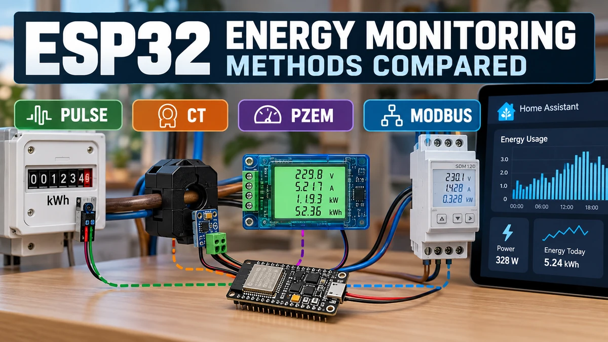
There is no single “best” ESP32AliExpress price energy-monitoring method because the four common approaches solve different problems. A pulse reader is the cheapest and safest way to read whole-home energy from an existing utility meter; its accumulated kWh effectively follows the meter’s own metrology, but it usually cannot tell you voltage, current, power factor or individual circuits. A CT clampAliExpress price is the best non-invasive way to monitor a specific circuit or whole-home current, but a CT alone measures current rather than true active power, so multiplying amps by 230 V is only an estimate unless you also measure voltage and phase. A PZEM-004TAliExpress price is the best low-cost DIY option when you want real voltage, current, watts, power factor, frequency and kWh from a single-phase circuit, but it requires mains-connected installation and is not the same class of installation as a certified DIN-rail meter. A Modbus DIN-rail meter such as an SDM120 or SDM630 is the best permanent solution when you need robust true-power measurement, import/export data, three-phase monitoring, long cable runs and professional switchboard installation. For most Home Assistant users: pulse reader for whole-home billing visibility, CT clampAliExpress price for easy circuit monitoring, PZEM for cheap detailed DIY metering, and Modbus for the serious permanent installation.
Materials You’ll Need
| Method | Typical hardware |
|---|---|
| Pulse meter | ESP32AliExpress price, optical/phototransistor sensor, USB power, light shield/holder |
| CT clamp | ESP32, suitable CT, ADC/burden/bias circuit or voltage-output CT |
| PZEM | ESP32, PZEM-004T v3.0, suitable current sensor/shunt version, insulated enclosure |
| Modbus DIN meter | ESP32, isolated or suitable RS-485 transceiver, SDM120/SDM630-class meter, twisted pair |
| Home Assistant + ESPHome | For local dashboards, Energy dashboard and automations |
| Multimeter | Useful for low-voltage debugging and verification |
Important safety note: a pulse reader can normally be installed without opening mains wiring. A CT clamp does not make an electrical connection to the conductor, but accessing conductors inside a distribution board can still expose dangerous voltages. PZEM and DIN-rail Modbus meters require direct mains wiring. Permanent mains work should be installed in a suitable enclosure and handled by a qualified electrician where required.
The Four Methods in One Table
| Feature | Pulse reader | CT clamp | PZEM-004T | DIN Modbus meter |
|---|---|---|---|---|
| Electrical connection to mains | No | No direct connection to CT itself | Yes | Yes |
| Whole-home energy | Excellent if meter LED accessible | Yes | Possible, model/current limit dependent | Excellent |
| Individual circuits | No | Excellent | Excellent | Excellent |
| True active power (W) | Derived from utility-meter pulses | Not from CT alone | Yes | Yes |
| Voltage | No | No | Yes | Yes |
| Current | No | Yes | Yes | Yes |
| Power factor | No | No with CT only | Yes | Yes |
| Frequency | No | No | Yes | Yes |
| Import/export direction | Depends on meter pulse behaviour | No with CT only | Usually limited/not ideal | Yes on suitable bidirectional meters |
| Three-phase | Meter total only if pulse represents total | Use one CT per phase | Not the normal PZEM-004T use | Yes with meters such as SDM630 |
| Installation difficulty | Very low | Low–medium | Medium–high | High |
| Typical cost | Lowest | Low | Low–medium | Medium–high |
| Best use | Billing/whole-home visibility | Non-invasive circuit monitoring | Low-cost detailed DIY meter | Permanent professional metering |
What Are You Actually Trying to Measure?
Before choosing hardware, decide which electrical quantity you actually need. “Energy monitoring” can mean several very different things.
| Quantity | Meaning | Unit |
|---|---|---|
| Voltage | Electrical potential | V |
| Current | Instantaneous RMS current flow | A |
| Active power | Power actually doing useful work | W |
| Apparent power | RMS voltage × RMS current | VA |
| Reactive power | Oscillating energy associated with reactive loads | var |
| Power factor | Relationship between active and apparent power | 0–1 |
| Energy | Power accumulated over time | Wh / kWh |
| Frequency | AC mains frequency | Hz |
A CT clamp by itself gives you current. A PZEM or proper energy meter simultaneously measures voltage and current and calculates real power. A pulse reader is different again: it is reading the output of an existing certified meter that has already done the electrical measurement internally.
Method 1: Electricity-Meter Pulse Reader
Many electronic utility meters have a front-panel LED marked with a constant such as 1000 imp/kWh, 2000 imp/kWh or 10000 imp/kWh. The LED flashes in proportion to accumulated energy. An ESP32 can detect those flashes with a phototransistor, photodiode or optical module and convert pulse timing into power and energy.
Utility meter LED
      ↓
Optical sensor
      ↓
ESP32 pulse_meter
      ↓
Home Assistant
  ├─ live power
  └─ total energy
Why Pulse Reading Can Be Surprisingly Accurate
The ESP32 is not estimating current or trying to reproduce the utility meter’s analogue front end. It is simply counting pulses generated by the meter itself. For accumulated energy, this means the result can track the meter extremely well apart from pulse resolution, missed pulses and any interpretation rules used by the meter.
If the meter is marked 1000 imp/kWh, one flash represents:
1 kWh / 1000 pulses = 0.001 kWh per pulse
                     = 1 Wh per pulse
At 10,000 imp/kWh, each pulse represents only 0.1 Wh, giving finer time resolution.
How Instantaneous Power Is Calculated from Pulses
If you measure the time between two pulses, average power is simply the energy represented by one pulse divided by the elapsed time.
Power (W) = 3,600,000 / (imp_per_kWh × seconds_between_pulses)For a 1000 imp/kWh meter, one pulse every 3.6 seconds corresponds to approximately 1000 W. One pulse every 36 seconds corresponds to approximately 100 W.
The Weakness of Pulse Monitoring: Low-Load Latency
At low power, flashes become infrequent. A meter with 1000 imp/kWh at a constant 20 W produces only about one pulse every three minutes. That means the accumulated energy remains correct, but the “live power” display reacts slowly.
ESPHome’s pulse_meter component is a good fit because it measures the time between pulses rather than only counting how many occurred in a fixed time window. That gives better low-rate resolution than a basic fixed-window pulse counter.
What a Pulse Reader Cannot Tell You
- Voltage
- Current
- Power factor
- Frequency
- Which circuit caused the load
- Phase-by-phase information
- Import/export direction unless the meter’s pulse output specifically represents it
A pulse reader tells you what the meter chooses to encode in that pulse stream. On a normal household import meter this is often enough for excellent whole-home consumption monitoring, but it is not a general-purpose electrical analyser.
Best Uses for a Pulse Reader
- Whole-home consumption without touching mains wiring
- Home Assistant Energy dashboard
- Cross-checking bills and daily consumption
- Low-cost rented-property monitoring where panel modifications are undesirable
- Situations where the utility meter is accessible but the distribution board should not be modified
Pulse Reader: Main Advantages and Disadvantages
| Advantages | Disadvantages |
|---|---|
| No electrical mains connection | Only works if a suitable pulse LED/output is accessible |
| Very low cost | No voltage/current/PF/frequency data |
| Accumulated kWh follows the utility meter | Low-load power can update slowly |
| Easy ESPHome integration | Ambient light can cause false pulses |
| Excellent whole-home solution | Cannot identify individual circuits |
Method 2: CT Clamp
A current transformer (CT) measures AC current by magnetically coupling to a conductor. A split-core CT can be clipped around an existing cable conductor without making an electrical connection to it.
The critical detail is that the CT must go around one current-carrying conductor, not an entire live-and-neutral cable together. If both conductors pass through the same CT, their magnetic fields largely cancel and the reading approaches zero.
ONE conductor through CT → current measured

Live + Neutral together through CT → fields cancel → near-zero reading
Current-Output vs Voltage-Output CTs
CT sensors are sold in two broad forms.
| CT type | What comes out | What the ESP32 needs |
|---|---|---|
| Current-output CT | Small AC current | External burden resistor + bias/ADC conditioning |
| Voltage-output CT | Low AC voltage | Burden is already inside; still needs suitable ADC/bias arrangement |
The popular SCT-013 family exists in multiple variants, so the exact model matters. Do not copy a burden-resistor value from another project unless the CT ratio/output is identical.
Why the ESP32 ADC Needs a Bias
A CT produces an AC waveform centred around zero. A normal ESP32 ADC cannot measure a negative voltage, so a conditioning circuit typically shifts the waveform to roughly half the ADC supply.
CT waveform:      -AC  0  +AC
                     ↓ bias
ESP32 ADC sees:  ~1.65 V ± waveform
ESPHome’s ct_clamp component samples the waveform and calculates RMS current while effectively removing the DC offset introduced by the bias circuit.
The Most Important CT Limitation: Current Is Not Power
A CT alone measures current. It does not know the instantaneous mains voltage waveform or the phase relationship between voltage and current.
The common shortcut is:
Estimated apparent power ≈ 230 V × currentFor a 5 A load this gives approximately 1150 VA. But if the real voltage is 236 V and the load has a power factor of 0.65, actual active power is much lower than 1150 W.
Active power ≈ Vrms × Irms × power factor

Example:
236 V × 5 A × 0.65 ≈ 767 W
This is why a basic CT-only project is excellent for relative load monitoring and current measurement but should not automatically be treated as a revenue-grade wattmeter.
Can a CT Clamp Detect Solar Import vs Export?
Not by itself. The magnitude of the current waveform looks similar whether power is flowing into or out of the house. To determine direction and true active power, the system needs a voltage reference and phase information, or a dedicated metering IC/meter designed for bidirectional energy measurement.
When a CT Project Becomes a Real Power Meter
A more advanced system samples both current and an isolated representation of the mains voltage waveform at the same time.
CT clamp → current waveform ─┐
                            ├→ simultaneous sampling → real power / PF
isolated voltage reference ─┘
At that point the project starts to resemble a dedicated energy-meter design. For permanent whole-home metering, a purpose-built metering IC or DIN-rail meter often becomes more sensible than expanding a basic CT circuit indefinitely.
Best Uses for CT Clamps
- Monitoring one appliance circuit
- Whole-home current monitoring where pulse output is unavailable
- Comparing loads without cutting conductors
- Detecting whether a heater, pump, compressor or EV charger is running
- Multi-circuit dashboards using several CT channels
CT Clamp: Main Advantages and Disadvantages
| Advantages | Disadvantages |
|---|---|
| No direct electrical connection to measured conductor | Requires access to a single conductor |
| Excellent for individual circuits | CT alone does not measure true active power |
| Low cost | Needs calibration and analogue design |
| Scales to many channels | ESP32 ADC quality/layout can affect low-current accuracy |
| Good for load signatures | Cannot determine direction without voltage phase reference |
Method 3: PZEM-004T
The PZEM-004T v3.0 sits between a hobby CT circuit and a professional DIN-rail meter. It is a low-cost dedicated AC energy-measurement module that measures the voltage and current waveforms internally and exposes calculated values digitally.
- Voltage
- Current
- Active power
- Active energy
- Frequency
- Power factor
This is a major upgrade over a CT-only project because the PZEM has the information needed to calculate real active power, not merely current or apparent-power estimates.
PZEM-004T Versions
| Version | Typical use |
|---|---|
| PZEM-004T 10 A | Direct/shunt measurement for lower-current single-phase loads |
| PZEM-004T 100 A | External current transformer for higher-current circuits |
The common v3.0 documentation specifies an 80–260 V voltage range, 45–65 Hz frequency range and active-energy accumulation up to 9999.99 kWh. Manufacturer specifications commonly quote about 0.5% measurement accuracy for voltage/current/power/energy and 1% for power factor, but those should be treated as module specifications rather than proof of utility billing certification.
Important: PZEM Also Uses Modbus
The word Modbus creates confusion in this comparison because the PZEM-004T v3.0 itself uses a Modbus-RTU-style register protocol over its serial interface.
PZEM-004T
  electrical meter module
  + TTL serial interface
  + Modbus-style register protocol

SDM120 / SDM630 class meter
  DIN-rail energy meter
  + RS-485 physical layer
  + Modbus RTU
  + professional switchboard form factor
So “PZEM vs Modbus” is not really a protocol comparison. It is a comparison between a cheap embedded metering module and a DIN-rail RS-485 energy meter.
PZEM Communication with ESP32
The ESP32 normally communicates with PZEM-004T v3.0 using a hardware UART. Multiple PZEM devices can be assigned different slave addresses, although practical multi-drop wiring deserves more care than a proper RS-485 bus.
ESPHome and Arduino libraries can expose the electrical measurements directly to Home Assistant, making PZEM one of the easiest ways to add detailed real-power data without writing a metering algorithm.
PZEM Safety and Installation
The PZEM is not an external sensor that can simply be taped to a cable. Its voltage-measurement section is connected to mains, and the module must be installed with appropriate insulation, terminals, enclosure, clearances and protection.
The 100 A external-CT version reduces the need to pass the full load current through the measurement PCB, but the module still needs a mains voltage connection for measurement and operation.
Where PZEM Is Better Than a Basic CT Clamp
| Measurement | Basic CT | PZEM-004T |
|---|---|---|
| Current | Yes | Yes |
| Voltage | No | Yes |
| True active power | No | Yes |
| Power factor | No | Yes |
| Frequency | No | Yes |
| Accumulated energy | Derived/estimated | Internal meter counter |
Where PZEM Is Weaker Than a DIN-Rail Modbus Meter
- Less convenient/professional enclosure and terminal format
- Normally aimed at single-phase DIY use
- Not the natural choice for three-phase systems
- Short TTL-style serial interface is less robust than differential RS-485 over long cable runs
- Certification and metering-class options are not comparable with certified DIN-rail meter families
- Bidirectional solar import/export measurement is not its strongest use case
Best Uses for PZEM
- Detailed monitoring of one single-phase appliance/circuit
- ESP32 + Home Assistant projects where watts and power factor matter
- Low-cost workshop or lab energy monitor
- Laundry/heat-pump/pump load signatures
- DIY sub-metering where certified billing is not required
PZEM: Main Advantages and Disadvantages
| Advantages | Disadvantages |
|---|---|
| Very low cost for true power data | Mains-connected installation |
| Voltage/current/watts/PF/frequency/kWh | Not as mechanically robust as DIN-rail meter |
| Easy ESP32 UART integration | Single-phase focus |
| No analogue ADC calibration on ESP32 side | Not the natural choice for certified billing |
| Good Home Assistant data set | TTL-style interface less robust than RS-485 |
Method 4: DIN-Rail Modbus Energy Meter
A DIN-rail Modbus energy meter is the most “professional” option in this comparison. Devices such as the Eastron SDM120 family for single-phase systems and SDM630 family for three-phase systems are designed to live in a distribution board and expose metering data over RS-485 Modbus RTU.
A suitable model can provide:
- Voltage
- Current
- Active power
- Apparent power
- Reactive power
- Power factor
- Frequency
- Import energy
- Export energy
- Demand values
- Per-phase values on three-phase models
Some meter variants are available with MID approval and specified metering accuracy classes, which moves them into a completely different category from a DIY analogue circuit.
Why RS-485 Matters
RS-485 uses a differential A/B pair rather than single-ended TTL serial. It is designed for electrically noisy environments, longer cable runs and multi-device buses.
ESP32 UART
    ↓
RS-485 transceiver
    ↓ A/B twisted pair
 ┌────────────┬────────────┬────────────┐
SDM120 #1   SDM120 #2   SDM630 / other Modbus device
Each slave has an address, so one ESP32 gateway can poll multiple meters or other Modbus equipment on the same bus, provided baud rate, parity, termination and addressing are designed correctly.
SDM120: Typical Single-Phase Use
The SDM120-Modbus class is a compact single-phase DIN meter. Current Eastron variants provide voltage, current, watts, power factor, frequency and energy data over RS-485, with some models supporting bidirectional import/export measurement and MID approval.
This makes an SDM120-style meter ideal for a heat pump, EV charger, solar feed, apartment sub-circuit or other permanent single-phase load where the installation should look like normal switchboard equipment.
SDM630: Typical Three-Phase Use
For three-phase supplies, an SDM630-class meter can expose per-phase voltages/currents plus total active/reactive/apparent power and accumulated import/export energy. That is far beyond what one PZEM-004T or one CT clamp can provide.
Three-phase energy monitoring is exactly where a proper meter becomes compelling because correct total power depends on measuring all phases and their electrical relationships consistently.
ESPHome Modbus Controller
ESPHome’s modbus_controller component can poll register maps directly. The official ESPHome documentation even includes an SDM120 example reading total active energy as a 32-bit floating-point value.
ESP32
  UART
   ↓
RS-485 transceiver
   ↓
SDM meter
   ↓ Modbus registers
ESPHome
   ↓
Home Assistant
The Real Difficulty with Modbus Is Not the Protocol
Once communication works, Modbus is simple: read registers and decode values. Most problems come from mismatched configuration.
- Wrong slave address
- Wrong baud rate
- Wrong parity/stop-bit settings
- A/B wires reversed
- Missing or inappropriate bus termination
- Wrong register type
- Wrong register offset
- Float byte/word-order mismatch
- Using the register map for a different meter revision
This is why the meter manual matters more than copying a random YAML snippet.
Best Uses for DIN Modbus Meters
- Permanent whole-home monitoring
- Solar import/export
- Three-phase supplies
- Heat pumps and EV chargers
- Professional sub-metering
- Long RS-485 cable runs
- Multiple energy meters on one ESP32 gateway
- Installations where certified/MID-approved meter variants matter
DIN Modbus: Main Advantages and Disadvantages
| Advantages | Disadvantages |
|---|---|
| Most complete measurement set | Highest hardware/installation cost |
| Professional DIN-rail form factor | Requires mains-panel installation |
| Robust RS-485 communications | Register maps/configuration add complexity |
| Excellent bidirectional/multi-phase options | More hardware than a simple DIY sensor |
| Certified meter variants available | Usually requires electrician for permanent install |
Accuracy: Which Method Wins?
“Accuracy” needs to be separated into energy accuracy, instantaneous-power accuracy and installation/calibration error.
| Method | Practical accuracy view |
|---|---|
| Pulse reader | Excellent accumulated-energy agreement with the existing utility meter if every pulse is captured correctly |
| CT clamp | Strong for current after calibration; power accuracy limited without voltage/PF measurement |
| PZEM-004T | Good low-cost true-power measurement; manufacturer commonly specifies ~0.5% for core quantities |
| DIN Modbus meter | Best defined/traceable option; choose model/accuracy class/certification appropriate to the job |
For checking your electricity bill, a pulse reader is often more useful than a beautifully calibrated DIY CT because it is literally tracking the billing meter’s energy output. For engineering analysis of a circuit, however, a meter that exposes voltage, current and PF is much more informative.
Update Speed: Which Feels Most ‘Real Time’?
| Method | Typical behaviour |
|---|---|
| Pulse reader | Fast at high loads, slow at low loads because it waits for pulses |
| CT clamp | Very responsive; sample/update interval is under your control |
| PZEM | Regular digital polling; usually plenty fast for Home Assistant |
| Modbus meter | Regular polling; typically 1–10 s is more than enough for dashboards |
If you want to detect that a washing machine just switched from heating to spinning, CT/PZEM/Modbus data is usually more responsive than a low-resolution meter pulse stream.
Safety: Which Method Is Least Invasive?
| Rank | Method | Safety / installation view |
|---|---|---|
| 1 | Optical pulse reader | Normally never touches mains wiring |
| 2 | CT clamp | No electrical connection, but panel access may still be hazardous |
| 3 | PZEM | Direct mains voltage connection; enclosure and wiring matter |
| 4 | DIN Modbus meter | Direct switchboard installation; professional installation strongly preferred |
“Non-invasive CT” does not mean “risk-free installation.” Opening a consumer unit to place the CT can expose live conductors even though the CT itself is isolated.
Best Method for Home Assistant Energy Dashboard
All four methods can ultimately feed Home Assistant, but they differ in how directly they produce a valid cumulative-energy sensor.
| Method | Home Assistant Energy dashboard |
|---|---|
| Pulse reader | Excellent — naturally counts meter energy |
| CT clamp | Needs power estimation and integration to kWh; quality depends on method |
| PZEM | Excellent — exposes internal cumulative energy |
| Modbus meter | Excellent — import/export kWh often available directly |
For solar or bidirectional grid monitoring, a meter that exposes separate import/export registers is far cleaner than trying to infer direction from a basic CT.
Best Method for Solar
Best: bidirectional DIN-rail Modbus meter.
Solar creates a directional-power problem. At different times the house can import from the grid or export to it. A current-only CT does not know direction, and a utility pulse LED may represent only one energy register depending on the meter.
A bidirectional Modbus meter can expose import watts/kWh and export watts/kWh directly. That is the most useful data model for Home Assistant solar dashboards.
PZEM can still be excellent for monitoring the output of a single inverter/circuit where power flow is known, but it is not my first choice for net-grid import/export metering.
Best Method for an EV Charger
If the EV charger is on its own circuit, a CT clamp is excellent for detecting current and charging state. If you want accurate kWh delivered to the car, voltage, power factor and long-term energy totals, PZEM or DIN Modbus is better.
For a permanent high-current installation, a DIN-rail meter is generally the cleanest solution because the hardware is designed to live in the distribution board.
Best Method for a Heat Pump
Heat pumps are a particularly good use case for detailed power monitoring because compressor speed, defrost cycles, immersion backup heating and circulation pumps create distinct power signatures.
A CT clamp is excellent for detecting those patterns. A PZEM adds true watts and power factor. A Modbus meter becomes attractive if you also want certified-style energy totals or the heat-pump installation already has RS-485 infrastructure.
Best Method for Appliance Cycle Detection
CT clamp or PZEM.
For a washing machine, dryer, dishwasher or pump, you care more about fast power signatures than about billing-grade accumulated kWh. PZEM gives the richest cheap data, while a CT is electrically simpler if approximate power is sufficient.
Best Method for Whole-Home Monitoring
There are two very different “best” answers.
- Cheapest/safest whole-home solution: optical utility-meter pulse reader.
- Best technically complete whole-home solution: suitable DIN-rail Modbus meter.
The pulse reader wins if the goal is simply “how much energy is my home using?” The Modbus meter wins if the goal is “show me voltage, current, real power, power factor, import/export and phase detail continuously.”
Best Method for Multi-Circuit Monitoring
CT clamps scale very naturally to many circuits because one small sensor can be clipped around each circuit conductor. A multi-channel ADC/metering board can then monitor multiple branches from one ESP32.
Installing a DIN energy meter on every circuit becomes expensive and consumes DIN-rail space, while multiple PZEM modules become mechanically messy. CTs therefore remain an excellent architecture for circuit-level energy dashboards even if a separate Modbus meter handles the whole-home reference measurement.
The Hybrid Approach Is Often Best
There is no rule saying a house must use only one method. In fact, the most useful Home Assistant setup often combines them.
Utility meter pulse reader
  → trusted whole-home kWh reference

CT clamps
  → individual circuits / appliances

Modbus meter
  → solar import/export / three-phase / high-value circuit

Home Assistant
  → combines everything
The whole-home pulse stream can even act as a sanity check against the sum of several CT/PZEM/Modbus measurements.
Cost vs Information
| Method | Relative cost | Information richness | Best value when… |
|---|---|---|---|
| Pulse reader | Very low | Low | You mainly want whole-home kWh/power |
| CT clamp | Low | Medium | You need circuit current/load detection |
| PZEM | Low–medium | High | You want cheap true electrical measurements |
| DIN Modbus | Medium–high | Very high | You want permanent/professional metering |
ESP32 Requirements
None of these methods requires a particularly powerful ESP32. The measurement hardware is doing most of the specialised work.
| Method | ESP32 requirement |
|---|---|
| Pulse | One digital GPIO with reliable interrupt/pulse measurement |
| CT | Good ADC input or external ADC; classic ESP32 ADC1 pins are commonly preferred |
| PZEM | One hardware UART |
| Modbus | One hardware UART + RS-485 transceiver |
An ESP32-C3 can handle pulse/PZEM/Modbus projects easily. A classic ESP32 remains attractive for CT projects because it offers many ADC1 options and is extremely well documented. The choice of measurement front end matters far more than whether the MCU is 160 MHz or 240 MHz.
ESPHome Support
| Method | ESPHome path |
|---|---|
| Pulse reader | pulse_meter |
| CT clamp | adc + ct_clamp |
| PZEM-004T v3 | Dedicated PZEM sensor component / UART |
| DIN Modbus | uart + modbus + modbus_controller |
This is one reason ESP32 energy monitoring works so well with Home Assistant: all four architectures can stay completely local without depending on a vendor cloud.
Common Mistake: Calling CT VA ‘Watts’
If a basic CT project calculates current × 230, call it estimated power or apparent power unless you have justified the power-factor assumption. Resistive heaters may be close to PF=1; motors, switch-mode supplies and variable-speed equipment may not be.
Common Mistake: Installing a CT Around Live and Neutral
The magnetic fields cancel. A CT needs one conductor. This is one of the most common reasons a new CT project reads almost zero.
Common Mistake: Treating a PZEM Like a Low-Voltage Sensor
The ESP32-facing serial connection is low voltage, but the PZEM measurement section is connected to mains. It belongs in an appropriate enclosure with safe clearances and terminals, not loose on a breadboard beside exposed mains wiring.
Common Mistake: Assuming Every Modbus Meter Uses the Same Registers
Even within one manufacturer family, register maps, data types and firmware options can differ. Always use the manual for the exact meter model and revision. The ESP32 code may be perfect while the register address is wrong.
Common Mistake: Ignoring Pulse Resolution
A 1000 imp/kWh pulse meter can be extremely good for energy totals but look “slow” at low loads. That is physics, not an ESP32 failure. At low consumption, the meter simply takes longer to accumulate enough energy to emit the next pulse.
My Recommendation by User Type
| User | Recommended method |
|---|---|
| Home Assistant beginner | Pulse reader if utility LED available |
| DIY electronics enthusiast | PZEM-004T for rich data at low cost |
| Non-invasive multi-circuit monitor | CT clamps |
| Solar / import-export system | Bidirectional Modbus meter |
| Three-phase home/workshop | Three-phase Modbus meter |
| Permanent professional installation | DIN-rail Modbus meter |
| Appliance load detection | CT or PZEM |
| Billing cross-check | Utility meter pulse reader |
Decision Flow
Can you access a utility-meter pulse LED and only need whole-home energy?
 └─ YES → Pulse reader
 └─ NO
     Need to avoid electrical connection to the circuit?
      └─ YES → CT clamp
      └─ NO
          Need a cheap single-phase DIY meter with V/A/W/PF/kWh?
           └─ YES → PZEM-004T
           └─ NO
               Need bidirectional, three-phase, robust RS-485 or certified meter options?
                └─ YES → DIN-rail Modbus meter
Final Recommendation
If I were building an ESP32 energy-monitoring system today, I would not try to force one sensor type to do everything.
Pulse reader = simplest whole-home truth source
CT clamp    = easiest non-invasive circuit sensor
PZEM        = cheapest detailed true-power meter
Modbus DIN  = best permanent/professional meter
The pulse reader is underrated because it is so simple: for whole-home accumulated energy it can follow the same utility meter used for billing without touching mains wiring. The CT clamp is unbeatable for easy circuit-level monitoring, but do not confuse RMS current with true watts. The PZEM-004T gives an extraordinary amount of electrical information for very little money and is ideal for serious DIY projects. The DIN-rail Modbus meter is what I would choose when the installation is permanent, three-phase, solar/bidirectional, or intended to behave like proper electrical infrastructure.
For a sophisticated Home Assistant installation, the best architecture may be a hybrid: one pulse or Modbus whole-home reference, plus CTs or PZEM modules on the circuits that matter most.
Related ESP32 Guides
- ESP32 Electricity Meter Pulse Reader for Home Assistant
- ESP32 CT Clamp Energy Monitor for Home Assistant
- ESP32 PZEM-004T Energy Monitor (ESPHome & MQTT)
- Home Assistant Modbus/RS-485 Gateway for Energy Meters & Heat Pumps
Datasheets & External Resources
All external manufacturer/framework references are collected here so the main article keeps readers inside esp32.co.uk.
- ESPHome Pulse Meter Sensor — pulse timing/counting component used for electricity-meter LED readers.
- ESPHome CT Clamp Sensor — official RMS-current sampling and calibration documentation.
- ESPHome Modbus Controller — RS-485/Modbus register polling, including an SDM120 example.
- PZEM-004T v3.0 Arduino Library & Specifications — community-maintained implementation and PZEM v3 measurement/protocol details.
- Eastron SDM120-M Modbus Meter — current single-phase DIN-rail meter specifications and bidirectional/MID options.
- Eastron Energy Meter Product Family — SDM series single- and three-phase energy meters.