
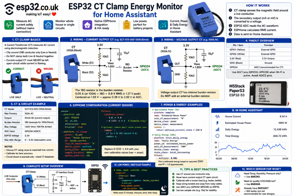
An ESP32 + CT current clamp + ESPHome can monitor AC current without electrically connecting the ESP32 to mains voltage. ESPHome’s native ct_clamp component samples the CT waveform, calculates RMS current and exposes it directly to Home Assistant. For a classic ESP32, use an ADC1 pin such as GPIO34 so Wi-Fi does not interfere with measurement. A current-output CT such as the SCT-013-000 needs an external burden resistor and 1.65 V bias circuit, while voltage-output CTs already contain their burden resistor. A CT alone measures current, not true active power: multiplying current by 230 V gives approximate apparent power, while accurate watts, power factor and import/export direction require simultaneous voltage measurement. (ESPHome – Smart Home Made Simple)
What is a CT clamp?
A current transformer, usually shortened to CT, measures alternating current by sensing the magnetic field around a conductor.
Split-core CTs are particularly convenient because they can open and clip around an existing insulated conductor. They are commonly used for monitoring:
- whole-house consumption
- individual circuits
- EV chargers
- heat pumps
- electric heaters
- solar inverter feeds
- workshop equipment
- server racks
The CT must normally surround one current-carrying conductor only. If both live and neutral pass through the clamp, their opposing magnetic fields largely cancel and the reading approaches zero. (OpenEnergyMonitor Documentation)
Important electrical safety
Although a split-core CT provides electrical isolation and does not normally make a metallic connection to the mains conductor, installing one inside a distribution board places the installer close to hazardous mains wiring. Power should be isolated before installation and work inside a consumer unit or panel should be carried out by someone competent to work safely on mains equipment. (Schneider Electric)
There is another less obvious CT-specific hazard.
A current-output CT must never be left open-circuit while current is flowing through its primary conductor. A current transformer can generate a dangerously high secondary voltage if its output is disconnected. Connect the burden/meter circuitry before placing the CT around an energised conductor, and remove the CT before disconnecting its secondary circuit. (Schneider Electric)
Voltage-output CTs have their burden resistor built in and do not have the same open-secondary issue. (OpenEnergyMonitor Documentation)
What this project measures
The basic ESP32 project measures:
RMS AC current in amps
For example:
House Current
7.42 A
From that current, an approximate power figure can be calculated:
Power ≈ Voltage × CurrentSo with an assumed 230 V supply:
230 V × 7.42 A
≈ 1707 VA
That is technically apparent power, not necessarily real power. Apparent power is Vrms × Irms; real power also depends on the relationship between the instantaneous voltage and current waveforms. (OpenEnergyMonitor Documentation)
For a nearly resistive heater, kettle or immersion heater, the two values can be very close.
For:
- motors
- refrigerators
- switch-mode power supplies
- electronic lighting
- inverter equipment
the difference can be significant.
CT clamp monitor vs real energy meter
This distinction matters if the project will feed Home Assistant’s Energy dashboard.
A current-only monitor can provide an excellent indication of:
Current
Load changes
When an appliance starts
Approximate apparent power
Approximate energy consumption
But it cannot directly determine:
Actual mains voltage
Power factor
True active power
Import vs export
To calculate true real power, voltage and current must be sampled together so instantaneous power can be calculated and averaged. (OpenEnergyMonitor Documentation)
For billing-grade or accurate solar import/export monitoring, use a proper voltage reference or a dedicated energy-metering solution such as an ATM90E26/ATM90E32-class device rather than relying on current × nominal voltage.
Choosing the CT clamp
The first thing to check is what comes out of the CT.
The YHDC SCT013 family, for example, is available with several output types, including:
- current output such as 100 A : 50 mA
- 1 V voltage output
- 0.333 V voltage output
YHDC currently lists 50 mA, 1 V and 0.333 V output options across the SCT013 range. (PowerUC Electronics)
These versions require different interface circuits.
Current-output CT
Example:
SCT-013-000: 100 A → 50 mA
This version requires an external burden resistor to convert secondary current into a voltage the ESP32 can measure. The SCT-013-000 is documented as a 100 A / 50 mA current-output device without an internal burden resistor. (OpenEnergyMonitor Documentation)
Voltage-output CT
Example:
100 A → 1 VThe burden resistor is already inside the clamp.
Do not add another normal burden resistor across a voltage-output CT unless the manufacturer’s circuit specifically requires it.
Why the signal needs a DC bias
A CT produces an AC waveform:
      +V
       /
      /
0V --    ----
            /
           /
      -V
An ESP32 ADC cannot accept a signal swinging below ground.
The AC waveform therefore needs to be shifted upward so that it oscillates around approximately half the ESP32’s supply voltage:
3.3 V
       /
      /
1.65 ----------
              /
             /
0 V
A simple resistor divider generates the 1.65 V bias.
Example bias circuit
A common circuit uses:
               3.3 V
                 │
                10k
                 │
                 ├──────── VBIAS ≈ 1.65 V
                 │
                10k
                 │
                GND

VBIAS ─────── 10 µF ───── GND
The capacitor stabilises the midpoint so the CT waveform is centred on a reasonably quiet 1.65 V reference.
Wiring a 100 A : 50 mA current-output CT
For a classic SCT-013-000-style 100 A / 50 mA CT, the circuit can look like this:
                       3.3 V
                         │
                        10k
                         │
             ┌──────── VBIAS
             │           │
             │          10k
             │           │
             │          GND
             │
             ├── 10µF ── GND
             │
             │
CT lead 1 ───┘

CT lead 2 ──────── GPIO34
             │
            18Ω
             │
             └────────── VBIAS
The 18 Ω resistor is the burden resistor in this specific example.
It is not a universal SCT-013 resistor value.
At the CT’s 100 A full-scale rating:
Secondary current = 50 mA RMS

V = I × R

0.05 × 18
= 0.90 V RMS
Its peak value is approximately:
0.90 × 1.414
≈ 1.27 V peak
With a 1.65 V bias, the ADC waveform therefore moves approximately between:
1.65 - 1.27 = 0.38 V

and

1.65 + 1.27 = 2.92 V
That gives useful headroom for the ESP32 ADC.
Use a reasonably accurate burden resistor, for example 1% tolerance, because its value directly affects current calibration.
Don’t blindly copy the 18 Ω resistor
The correct burden depends on:
- CT current ratio
- maximum current
- ADC voltage range
- bias voltage
- desired headroom
A 30 A CT, 50 A CT and 100 A CT may all require different values.
Likewise, a:
100 A / 1 VCT is fundamentally different from:
100 A / 50 mABefore building the circuit, identify the exact CT model and its output type.
Wiring a 1 V output CT
A CT with an internal burden is easier.
Conceptually:
             3.3 V
               │
              10k
               │
      ┌───── VBIAS
      │        │
      │       10k
      │        │
      │       GND
      │
      ├─10µF──GND
      │
CT ───┤
      │
      └──────── GPIO34
The exact interface depends on whether the breakout/module already includes bias and protection components.
Some ready-made ESPHome CT interface boards already contain everything between the CT jack and ADC input.
Why use GPIO34?
On the original ESP32, the safest analog inputs for a Wi-Fi project are the ADC1 pins GPIO32–GPIO39.
ESPHome documents the original ESP32 ADC arrangement as:
ADC1:
GPIO32–GPIO39

ADC2:
GPIO0, 2, 4, 12–15, 25–27
ADC2 cannot normally be used while Wi-Fi is configured, so an ADC1 input such as GPIO34 is a good choice for a Home Assistant node. (ESPHome – Smart Home Made Simple)
GPIO34 is also input-only, which is perfectly fine because the CT signal only needs to be measured.
ESPHome CT clamp configuration
ESPHome includes a dedicated:
platform: ct_clampsensor.
It takes measurements from a voltage-sampling source such as:
and calculates the AC RMS component. (ESPHome – Smart Home Made Simple)
A simple starting configuration is:
sensor:
  - platform: adc
    pin: GPIO34
    id: ct_adc
    attenuation: auto
    internal: true

  - platform: ct_clamp
    sensor: ct_adc
    name: "House Current"
    id: house_current
    unit_of_measurement: "A"
    device_class: current
    state_class: measurement
    sample_duration: 500ms
    update_interval: 10s
attenuation: auto allows ESPHome to select across the ESP32 ADC ranges. ESPHome currently documents an approximate usable auto-attenuation range of about 0.075–3.12 V, although the exact limits vary between chips. (ESPHome – Smart Home Made Simple)
Why sample for 500 ms?
ESPHome’s ct_clamp defaults to a 200 ms sample duration.
On a 50 Hz system that already covers ten complete mains cycles. Longer sample periods can improve consistency, although they also require more processing time. (ESPHome – Smart Home Made Simple)
A practical starting point is:
sample_duration: 500ms
update_interval: 10s
There is usually little benefit in publishing household energy readings dozens of times per second to Home Assistant.
Calibration is mandatory
Even if the CT ratio and burden resistor are theoretically correct, the complete measurement chain includes:
- CT ratio tolerance
- burden resistor tolerance
- ESP32 ADC characteristics
- wiring
- component tolerances
- clamp positioning
So the final system should be calibrated against a known measurement.
ESPHome specifically recommends using calibrate_linear with a known current load. (ESPHome – Smart Home Made Simple)
Suppose the ESPHome logs show:
CT value = 0.1333while a trusted meter shows:
4.00 AThe ESPHome documentation gives this style of calibration:
filters:
  - calibrate_linear:
      - 0.0 -> 0.0
      - 0.1333 -> 4.0
The 0.1333 value above is only an example from ESPHome’s documentation. Replace it with the reading from the actual circuit and reference meter. (ESPHome – Smart Home Made Simple)
Complete calibrated current sensor example
sensor:
  - platform: adc
    pin: GPIO34
    id: ct_adc
    attenuation: auto
    internal: true

  - platform: ct_clamp
    sensor: ct_adc
    name: "House Current"
    id: house_current

    sample_duration: 500ms
    update_interval: 10s

    unit_of_measurement: "A"
    device_class: current
    state_class: measurement
    accuracy_decimals: 2

    filters:
      - calibrate_linear:
          - 0.0 -> 0.0

          # EXAMPLE ONLY:
          # Replace with your actual measured calibration point
          - 0.1333 -> 4.0

      # Remove tiny ADC/CT noise around zero
      - lambda: |-
          if (x < 0.10) {
            return 0.0;
          }
          return x;
The final small-current threshold is optional. Set it only after observing the noise floor of the actual installation.
Calibration with a known appliance
A resistive appliance makes a useful test load because its current is relatively stable.
Possible examples include:
- electric heater
- kettle
- incandescent lamp load
A clamp meter can provide the reference current.
Measure:
Reference meter = 8.25 A
ESPHome before calibration = 7.71 A
Then use those values as the calibration point.
For higher accuracy, calibrate at more than one load level rather than relying on only a single point.
Calculating approximate power
A current-only monitor can create an estimated power sensor.
For a 230 V example:
  - platform: template
    name: "Estimated House Power"
    id: estimated_house_power

    unit_of_measurement: "W"
    device_class: power
    state_class: measurement
    accuracy_decimals: 0

    update_interval: 10s

    lambda: |-
      return id(house_current).state * 230.0;
This assumes:
Voltage = 230 V
Power factor = 1.0
So it should be labelled estimated.
Without voltage waveform measurement, the ESP32 is really calculating apparent power from an assumed voltage. OpenEnergyMonitor likewise notes that apparent power can be estimated from a nominal supply voltage when only RMS current is available. (OpenEnergyMonitor Documentation)
Better approximate power with an assumed power factor
If a known appliance has a reasonably consistent power factor, the estimate can include it:
Power ≈ Voltage × Current × PFFor example:
lambda: |-
  return id(house_current).state * 230.0 * 0.95;
But this does not solve the problem for whole-house monitoring because the combined power factor changes as different appliances turn on and off. Real power requires simultaneous voltage and current measurements. (OpenEnergyMonitor Documentation)
Calculating daily energy
Once there is a power entity, ESPHome can integrate it over time using total_daily_energy.
ESPHome converts power readings in W or kW into accumulated Wh or kWh and resets the daily total using a configured time source. (ESPHome – Smart Home Made Simple)
Add:
sensor:
  - platform: total_daily_energy
    name: "Estimated Daily Energy"
    power_id: estimated_house_power

    unit_of_measurement: "kWh"
    device_class: energy
    state_class: total_increasing
    accuracy_decimals: 3

    filters:
      - multiply: 0.001

time:
  - platform: homeassistant
    id: homeassistant_time
This value can be displayed in Home Assistant as estimated daily consumption.
Remember that integrating approximate power produces approximate energy.
Lifetime energy instead of daily energy
ESPHome’s generic integration sensor can integrate power continuously rather than resetting at midnight. (ESPHome – Smart Home Made Simple)
For example:
  - platform: integration
    name: "Estimated Total Energy"
    sensor: estimated_house_power
    time_unit: h

    unit_of_measurement: "kWh"
    device_class: energy
    state_class: total_increasing

    filters:
      - multiply: 0.001
ESPHome can optionally restore integrated values after restart, although its documentation warns that persistent writes can contribute to flash wear. (ESPHome – Smart Home Made Simple)
Home Assistant entities
With the configuration above, Home Assistant can show:
House Current
8.24 A

Estimated House Power
1895 W

Estimated Daily Energy
12.438 kWh

Estimated Total Energy
846.72 kWh
These can then be used in:
- dashboards
- history graphs
- alerts
- automations
- appliance detection
- high-load warnings
High-current alert
A useful automation could be:
House Current > 50 A
for 30 seconds
→ send notification
This is useful for identifying unexpectedly high loads, but it is not a substitute for circuit breakers or any electrical protection device.
The ESP32 energy monitor is monitoring equipment, not safety equipment.
Detecting appliance operation
A CT clamp can also be used on one dedicated circuit rather than the whole house.
For example:
Current < 0.2 A
→ appliance OFF

Current > 2 A
→ appliance ON
This can create Home Assistant binary sensors for:
- immersion heaters
- ovens
- pumps
- washing machines
- air conditioners
- workshop tools
It can sometimes be more reliable than relying on whether a smart plug happens to be connected.
CT clamp around live and neutral gives almost zero
This is the most common installation mistake.
A CT must normally surround:
Live only
or, on an appropriate single-phase circuit:
Neutral only
If it surrounds the complete twin-core cable, equal current flows in opposite directions and the magnetic fields cancel. (OpenEnergyMonitor Documentation)
Correct:
       ┌──── CT ────┐
LIVE ──┤            ├────
       └────────────┘

NEUTRAL ─────────────────
Wrong:
       ┌──── CT ────┐
LIVE ──┤            ├────
NEUTRAL┤            ├────
       └────────────┘
Reading stays above zero when everything is off
Small values can come from:
- ADC noise
- bias noise
- electromagnetic interference
- CT pickup
- quantisation
- poor grounding
First observe the stable no-load reading.
Then apply a small threshold such as:
filters:
  - lambda: |-
      if (x < 0.10) return 0.0;
      return x;
Do not make the threshold excessively large or legitimate low-power loads will disappear.
Reading is inaccurate at low current
A 100 A CT spends only a tiny fraction of its full-scale output measuring a 0.2 A load.
For better low-current resolution, choose a CT whose current rating is reasonably close to the circuit being measured. OpenEnergyMonitor similarly recommends choosing CT ratings that suit the monitored circuit—for example, using smaller-rated CTs on lower-current branch circuits rather than using a 100 A CT everywhere. (OpenEnergyMonitor Documentation)
For example:
16 A circuit
→ 20 A CT can be preferable

32 A EV charger
→ 50 A CT

Whole-house 100 A supply
→ 100 A CT
This uses more of the ADC’s available range.
ESP32 ADC vs ADS1115
The internal ESP32 ADC is inexpensive because it requires no extra hardware, and ESPHome applies manufacturer-supported calibration to its ADC readings. ESPressif notes that the true ADC reference varies between chips, which is why calibration is important. (Espressif Systems)
For a more measurement-focused design, an ADS1115 external ADC is another option. ESPHome explicitly supports voltage-sampler sources such as ADS1115 for the ct_clamp component. (ESPHome – Smart Home Made Simple)
Advantages can include:
- more predictable ADC behaviour
- higher resolution
- easier multi-channel designs
- reduced dependence on the ESP32’s internal ADC characteristics
For a simple single CT project, the internal ESP32 ADC is usually sufficient once calibrated.
Monitoring several circuits
Multiple CT channels can be added.
For example:
CT1 → Whole House
CT2 → Heat Pump
CT3 → EV Charger
CT4 → Kitchen
Each needs its own analogue measurement channel and appropriate signal-conditioning circuit.
An external multi-channel ADC can become attractive here because it keeps the analogue measurement hardware together rather than consuming multiple ESP32 ADC pins.
Three-phase monitoring
A three-phase installation generally requires a CT for each phase if the goal is to understand the complete load accurately.
Conceptually:
L1 → CT1
L2 → CT2
L3 → CT3
A current-only system can report the RMS current on each phase.
Accurate total real power, however, again requires appropriate voltage information and phase-aware measurement. OpenEnergyMonitor treats three-phase real-power monitoring separately for this reason. (OpenEnergyMonitor Documentation)
Can this measure solar import and export?
Not correctly with only one current waveform.
RMS current has magnitude but does not tell the ESP32 whether energy is flowing:
Grid → Houseor:
House → GridDetermining power direction requires the relationship between the voltage and current waveforms. Real power changes sign according to the direction of energy flow, while RMS current and apparent power remain positive. (OpenEnergyMonitor Documentation)
For a solar installation, use a monitor capable of simultaneous voltage and current measurement if import/export direction matters.
How to make it a real power meter
The next level adds an isolated AC voltage reference.
Conceptually:
CT clamp
→ current waveform

Isolated AC voltage transformer
→ voltage waveform

ESP32 / energy-meter IC
→ sample both simultaneously

→ Vrms
→ Irms
→ Real Power
→ Apparent Power
→ Power Factor
→ Energy
→ Import / Export
An isolated AC-AC transformer can provide a safe low-voltage representation of the mains voltage waveform while maintaining galvanic isolation. (OpenEnergyMonitor Documentation)
For a permanent whole-home meter, a dedicated metering IC or commercial DIN-rail meter with Modbus is often a better choice than pushing the basic CT-clamp circuit beyond its intended purpose.
Recommended first build
For a simple Home Assistant monitor using a classic ESP32:
| Part | Suggested choice |
|---|---|
| MCU | ESP32 DevKit |
| ADC pin | GPIO34 |
| CT | Appropriate split-core CT |
| Current-output example | 100 A : 50 mA |
| Burden example | 18 Ω for the specific 100 A : 50 mA circuit described above |
| Bias divider | 10 kΩ + 10 kΩ |
| Bias capacitor | 10 µF |
| ESPHome component | ct_clamp |
| Sample duration | 500 ms |
| Update interval | 10 s |
For a voltage-output CT, omit the external burden and follow the electrical requirements of that exact CT model.
Final recommendation
An ESP32 CT clamp monitor is an excellent low-cost Home Assistant project when the main requirement is:
“How much AC current is this circuit drawing?”
ESPHome already provides the difficult RMS sampling logic through its native ct_clamp component, including configurable sample duration and straightforward linear calibration. (ESPHome – Smart Home Made Simple)
The most important rules are:
- clamp around one conductor, not the whole cable
- identify whether the CT is current-output or voltage-output
- never leave a current-output CT open-circuit while it surrounds an energised conductor
- bias an AC signal correctly before feeding an ESP32 ADC
- use an ADC1 GPIO on the original ESP32 when Wi-Fi is active
- calibrate against a trusted current measurement
- treat
230 V × currentas an estimate, not billing-grade real power
For Home Assistant load monitoring, appliance detection and general energy-awareness projects, that is often all that is required.
For accurate watts, power factor, solar import/export or billing-quality energy, add real voltage measurement or move to a dedicated energy-metering IC or meter.