
The SSD1306 OLED displayPriceAliExpress price is a compact monochrome screen for ESP32 sensor readouts, menus, status panels and small graphics. Popular versions include 0.96-inch 128×64 and 0.91-inch 128×32 modules. Despite their similar appearance, a common four-pin I²C module, a seven-pin SPI module, and an Adafruit configurable breakout are not wired or configured in the same way.
In this esp32.co.uk/ article, we compare the actual board functions, identify I²C address settings, explain the Adafruit rear jumpers, and provide a complete Arduino IDE example using the Adafruit SSD1306 and Adafruit GFX libraries. Connection illustrations use pin-to-pin tables rather than misleading AI-drawn wires. Each companion image is specified with visible esp32.co.uk/ branding.
Quick answer: for a verified 3.3 V-compatible four-pin I²C OLED and a classic ESP32-WROOM DevKit, connect VCC→3V3, GND→GND, SDA→GPIO21 and SCL→GPIO22. Scan the I²C bus and initialize at its detected address, usually 0x3C on generic modules. Some Adafruit 128×64 examples use 0x3D. Screen resolution by itself does not determine the address.
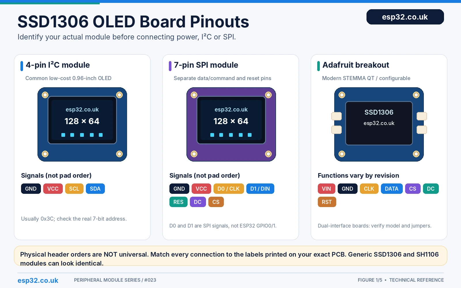
SSD1306 specifications and breakout-board differences
| Property | SSD1306 reference |
|---|---|
| Controller | Solomon Systech SSD1306, or a compatible part; check for SH1106 substitutes |
| Pixel options | Common 128×64 and 128×32 monochrome configurations |
| Bus | I²C or SPI depending on the breakout configuration |
| I²C address | 7-bit 0x3C or 0x3D, set by board hardware |
| Graphics buffer | 128×64 = 1,024 bytes; 128×32 = 512 bytes in the MCU library buffer |
| Power | Low-voltage raw controller; breakout VIN/VCC rating varies by manufacturer |
| Current | Depends on brightness and illuminated pixels, not a fixed load |
| Display type | Self-emitting OLED; no separate LEDPrice backlight supply |
| Libraries | Adafruit SSD1306 + GFX; U8g2 is an alternative for fonts and other controllers |
The driver creates a 1-bit pixel image; each pixel is either off or on, even when a physical display emits blue, white, yellow or a mix of panel zones. It supports text, simple plots, icons and custom monochrome bitmaps. The Adafruit library allocates the corresponding framebuffer on the ESP32 and transmits the buffer when display.display() is called.
Four-pin I²C module pinout
A typical inexpensive 0.96-inch I²C board carries GND, VCC, SCL, SDA. Some batches reverse the power positions or the order of the signals. The table lists functional names, not a universal left-to-right header order. Supplying power through the wrong pad can destroy the module, even if a random online diagram looks reassuring.
| Printed pin | Function | ESP32 connection |
|---|---|---|
| GND | Ground return | GND |
| VCC | Power input: use 3.3 V only when the board supports it | 3V3 |
| SCL/SCK | I²C serial clock | GPIO22 |
| SDA | I²C serial data | GPIO21 |
Logic warning: the SSD1306 silicon is a low-voltage part. Some complete modules have a regulator and allow 5 V on VCC; that does not necessarily mean their I²C pull-ups are safe for an ESP32. Use a verified 3.3 V-compatible breakout and a 3.3 V I²C bus. If a module claims 5 V compatibility, confirm both power and signal-level specifications.
Adafruit #326 / #938: different functions from basic four-pin boards
Adafruit’s 0.96-inch 128×64 #326 and 1.3-inch 128×64 #938 are manufacturer-specific breakouts. Current STEMMA QT versions add a regulator, digital-level circuitry and automatic reset. Their configurable boards provide functions including VIN, 3Vo, GND, CLK, DATA, RST, DC, CS and an address-selection option (sometimes marked A0). Position and jumper artwork vary by revision.
| Breakout marking | I²C role | SPI role |
|---|---|---|
| VIN | Power input; 3.3 V is suitable with ESP32 | Same power input |
| 3Vo | Onboard regulated 3.3 V output, not VIN | Same output |
| GND | Ground | Ground |
| CLK / SCK | I²C SCL | SPI SCLK |
| DATA / SDI | I²C SDA | SPI MOSI |
| A0 / ADDR | Board-specific 0x3C/0x3D selection | Not an ESP32 analogue pin |
| DC | No separate I²C data/command wire | Data/command control |
| CS | No I²C chip-select wire | SPI chip select, active low |
| RST | Optional if auto-reset circuit is fitted | Reset where required |
The two STEMMA QT connectors on equipped Adafruit boards carry the same I²C bus; they are not two independently addressed display ports. The newer Adafruit breakouts are generally configured for I²C at the factory, while older versions may ship in SPI mode. Adafruit documents specific mode jumpers on each PCB revision. Never cut or bridge pads based only on a generic photograph.
Seven-pin SPI display pinout
Many generic SPI SSD1306 modules expose seven functions such as GND, VCC, D0, D1, RES, DC, CS. Here D0 means SPI clock, and D1 means serial data input (MOSI). They are not references to ESP32 GPIO0 or GPIO1. The ESP32 normally does not need an OLED MISO connection for this write-only display.
| SPI module pin | Signal function | Classic ESP32 example |
|---|---|---|
| GND | Common ground | GND |
| VCC | Compatible module power | 3V3 |
| D0 / CLK | SPI SCLK | GPIO18 |
| D1 / SDA / DIN | SPI MOSI | GPIO23 |
| RES / RST | Active-low reset | GPIO16 |
| DC / A0 | Data versus command | GPIO17 |
| CS | Active-low chip select | GPIO5 |
An OLED sold with only four I²C connections generally cannot become a seven-pin SPI module through code alone. The necessary SPI control signals must be physically available on the PCB. For an Adafruit dual-interface breakout, follow its documented interface-jumper procedure rather than copying the jumper positions of a generic display.
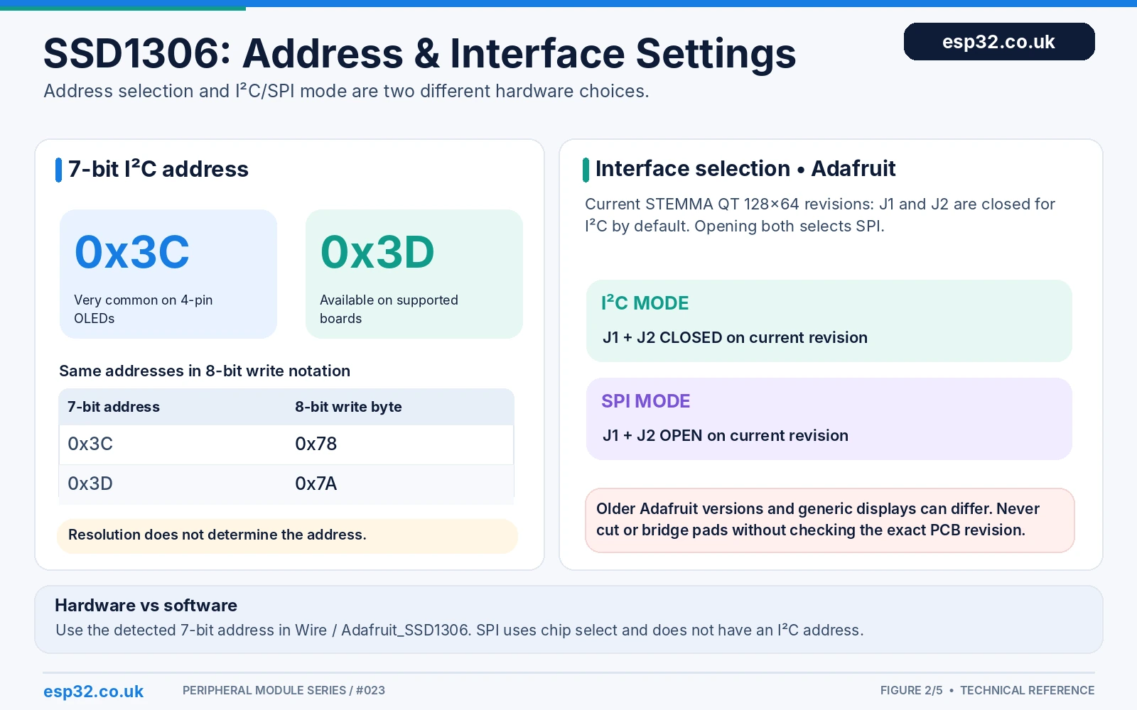
I²C address 0x3C versus 0x3D and solder-pad settings
The SSD1306 has two normal seven-bit I²C addresses, determined by the controller’s SA0 state. The physical board implements that state through a solderPriceAliExpress price bridge, resistor or fixed connection. A generic 128×64 board commonly answers at 0x3C; Adafruit’s examples often use 0x3D for a 128×64 panel. Neither address is an automatic consequence of pixel resolution.
| Label / value | Meaning |
|---|---|
| 0x3C | Common seven-bit SSD1306 address |
| 0x3D | Alternative seven-bit SSD1306 address |
| 0x78 / 0x7A | Eight-bit write-address notations; do not use these in Wire.beginTransmission() |
| ADDR / A0 on a documented board | I²C address select; exact bridged state varies by module |
| J1 / J2 on certain Adafruit revisions | Select I²C versus SPI; not necessarily the address jumpers |
For some modern Adafruit boards, converting from factory I²C to SPI requires opening or cutting the two marked mode jumpers. Some older boards use a different jumper arrangement and default mode. A power LED jumper is another entirely different function. Confirm what each pad does from the exact manufacturer and revision before touching a soldering ironAliExpress price.
ESP32 I²C scanner: check the address before anything else
The following short scanner probes both normal SSD1306 addresses on an ESP32. It can confirm that something acknowledges the bus, but it cannot prove the exact OLED controller; SH1106 modules can appear at the same addresses.
#include <Arduino.h>
#include <Wire.h>
void setup() {
  Serial.begin(115200);
  Wire.begin(21, 22);  // SDA, SCL on classic ESP32
  Wire.setClock(100000);
  for (uint8_t addr : {uint8_t(0x3C), uint8_t(0x3D)}) {
    Wire.beginTransmission(addr);
    if (Wire.endTransmission() == 0)
      Serial.printf("Display/I2C device at 0x%02X\n", addr);
  }
}
void loop() {}
If neither address responds, verify the interface mode, voltage, shared ground, pin order and bus pull-ups. Keep the clock at 100 kHz while troubleshooting. An I²C scanner may still report a device even if the display glass, controller initialization or graphics library is wrong.
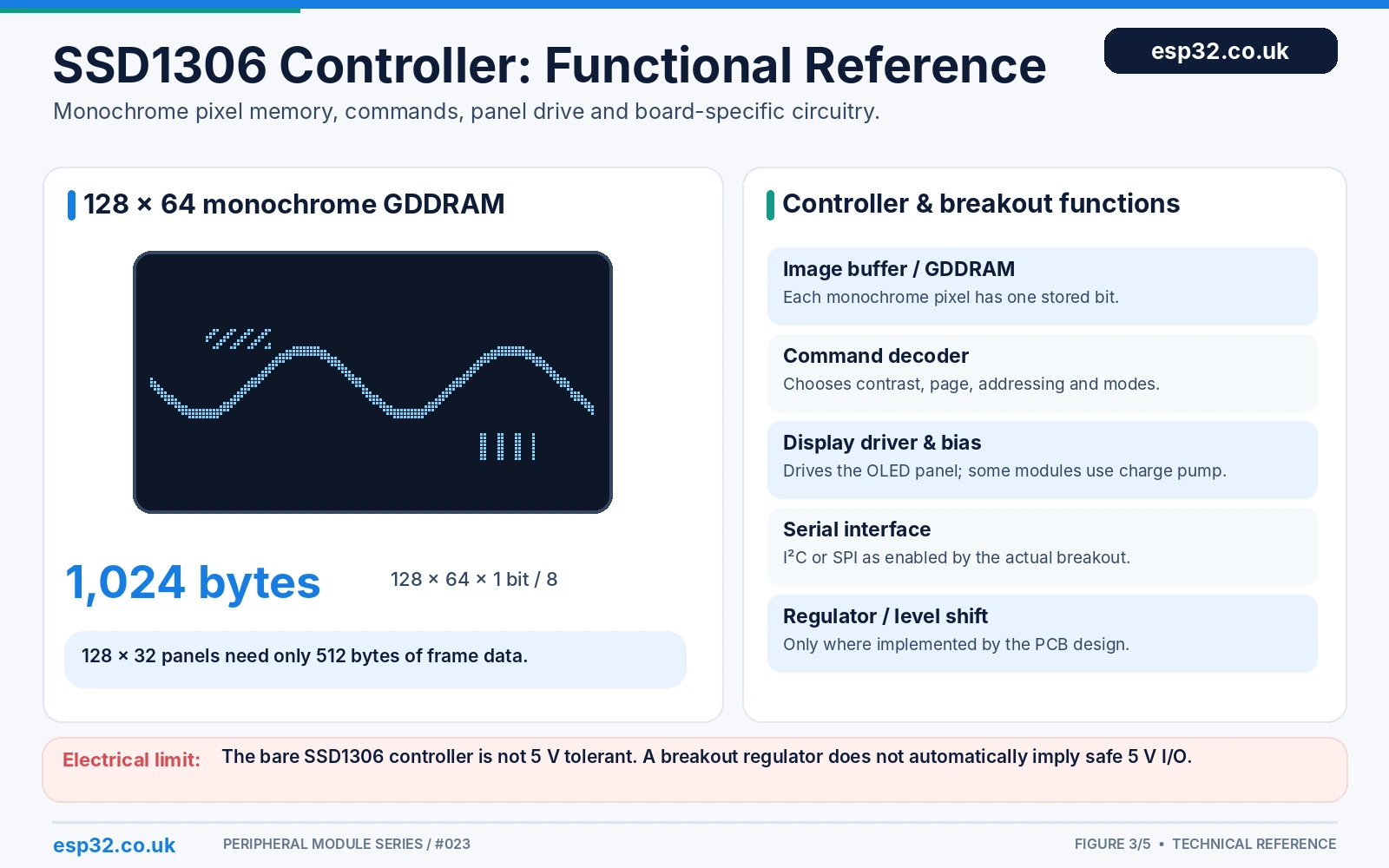
Functional reference: controller, frame RAM and voltage domains
The SSD1306 contains row/column output drivers, command decoding, display data RAM (GDDRAM) and panel-voltage generation circuitry. The breakout adds power handling and sometimes reset, regulator or level shifting components. A bare controller’s voltage limits are not interchangeable with the larger-looking VIN label on an Adafruit board.
| Block | Function |
|---|---|
| Logic supply | Low-voltage controller power; verify bare chip requirements |
| Panel supply / charge pump | Higher OLED panel bias produced or managed as specified by module design |
| GDDRAM | 128×64 monochrome image = 1,024 bytes; 128×32 = 512 bytes |
| I²C interface | SDA, SCL and 0x3C/0x3D address selection |
| SPI interface | SCLK, MOSI, CS, DC and reset as implemented by PCB |
| Breakout support | Capacitors, pull-ups, voltage regulator and reset vary by manufacturer |
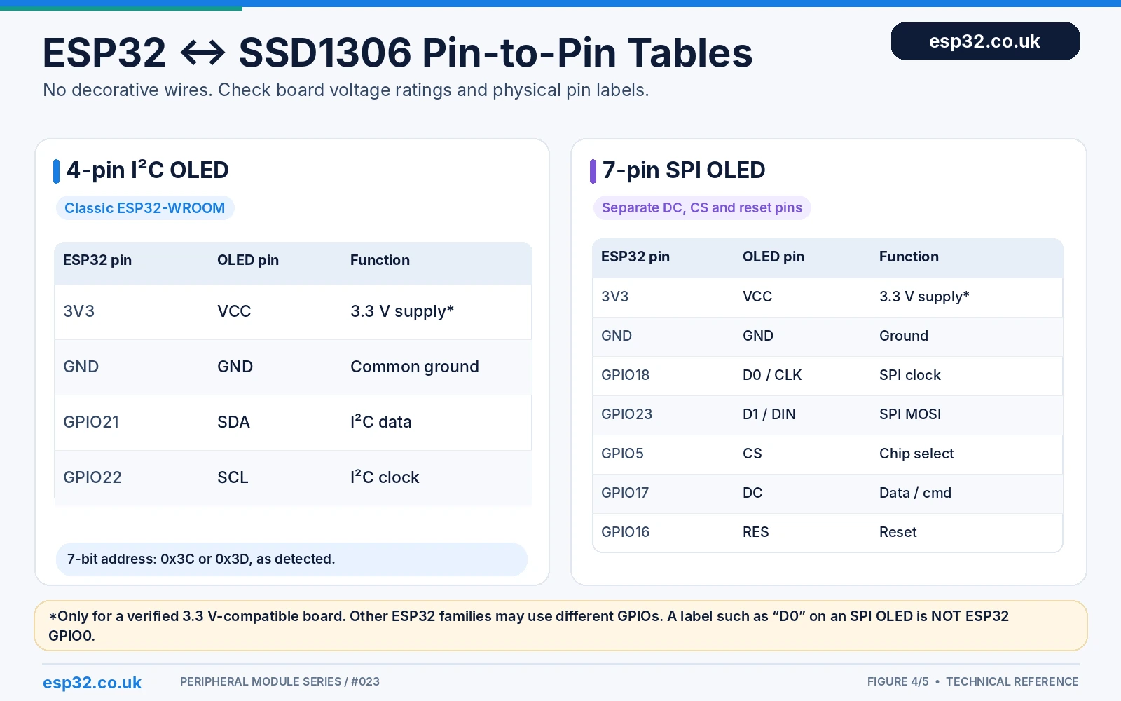
ESP32 connection tables: I²C and SPI side by side
The following pin choices are for a classic ESP32-WROOM DevKit; newer ESP32-C3, C6 and S3 boards can require different pins. The SPI table is for an actual seven-pin SPI board and does not apply to four-pin I²C-only modules.
| ESP32 pin | Four-pin I²C OLED | Function |
|---|---|---|
| 3V3 | VCC | Supply if module supports 3.3 V |
| GND | GND | Common ground |
| GPIO21 | SDA | Data |
| GPIO22 | SCL | Clock |
| ESP32 pin | Seven-pin SPI OLED | Function |
|---|---|---|
| 3V3 | VCC | Supply |
| GND | GND | Ground |
| GPIO18 | D0/CLK | SPI SCLK |
| GPIO23 | D1/DIN | SPI MOSI |
| GPIO5 | CS | Chip select |
| GPIO17 | DC | Data / command |
| GPIO16 | RES/RST | Reset |
Do not connect a separate 5 V pull-up to ESP32 GPIOs. On an I²C module, SCL and SDA share the bus with any other I²C sensors provided addresses are unique and the voltage/pull-up network is compatible. A 0x3C screen and a 0x3D screen can coexist, but two identical 0x3C displays require separate buses or an I²C multiplexer if independent access is needed.
Arduino IDE: complete SSD1306 128×64 I²C example
Install Adafruit SSD1306 and Adafruit GFX Library in Arduino IDE Library Manager, along with any prompted dependency. This example scans 0x3C and 0x3D, then draws a simple ESP32 status panel and sends the framebuffer to the OLED once per second. The display dimensions are explicitly 128×64; change them for a 128×32 variant.
#include <Arduino.h>
#include <Wire.h>
#include <Adafruit_GFX.h>
#include <Adafruit_SSD1306.h>

constexpr int SDA_PIN = 21;
constexpr int SCL_PIN = 22;
constexpr int OLED_W = 128;
constexpr int OLED_H = 64;

Adafruit_SSD1306 oled(OLED_W, OLED_H, &Wire, -1);
uint8_t address = 0;

uint8_t locateOLED() {
  const uint8_t candidates[] = {0x3C, 0x3D};
  for (uint8_t addr : candidates) {
    Wire.beginTransmission(addr);
    if (Wire.endTransmission() == 0) return addr;
  }
  return 0;
}

void setup() {
  Serial.begin(115200);
  Wire.begin(SDA_PIN, SCL_PIN);
  Wire.setClock(100000);
  address = locateOLED();
  if (!address) {
    Serial.println("No OLED at 0x3C or 0x3D");
    while (true) delay(1000);
  }
  // Keep existing ESP32 Wire.begin(SDA,SCL) configuration.
  if (!oled.begin(SSD1306_SWITCHCAPVCC, address, true, false)) {
    Serial.println("OLED buffer allocation failed");
    while (true) delay(1000);
  }
  Serial.printf("SSD1306 I2C address: 0x%02X\n", address);
}

void loop() {
  oled.clearDisplay();
  oled.setTextSize(1);
  oled.setTextColor(SSD1306_WHITE);
  oled.setCursor(12, 5);
  oled.println("esp32.co.uk/");
  oled.drawLine(0, 18, 127, 18, SSD1306_WHITE);
  oled.setCursor(5, 28);
  oled.print("Up: ");
  oled.print(millis()/1000);
  oled.println(" sec");
  oled.setCursor(5, 45);
  oled.print("I2C: 0x");
  oled.println(address, HEX);
  oled.display(); // Flush framebuffer to glass.
  delay(1000);
}
The code uses the documented Adafruit_SSD1306(width, height, &Wire, reset) constructor and the four-argument begin(). Setting the final argument to false avoids reinitializing an already configured ESP32 I²C bus. The sketch has been API-reviewed against Adafruit’s current library but not physically bench-tested on every module. If the controller is SH1106 rather than SSD1306, use the correct display library instead.
Why display.display() is essential
Calls such as print() and drawLine() modify a memory buffer in the ESP32. The visible display only updates when oled.display() transfers that buffer to the SSD1306. A common blank-screen bug is to draw successfully but forget to flush the frame. The size of the OLED, font scaling and coordinates also matter: text below y=31 is invisible on a 128×32 panel.
Optional: hardware SPI sketch for a seven-pin OLED
Use this only when the board is really configured for SPI. The ESP32 pin choices match the earlier table. SPI communication does not use the I²C address at all.
#include <Arduino.h>
#include <SPI.h>
#include <Adafruit_GFX.h>
#include <Adafruit_SSD1306.h>
constexpr int OLED_DC = 17;
constexpr int OLED_RST = 16;
constexpr int OLED_CS = 5;
Adafruit_SSD1306 screen(128, 64, &SPI,
                       OLED_DC, OLED_RST, OLED_CS);
void setup() {
  SPI.begin(18, 19, 23, OLED_CS); // MISO unused by OLED.
  if (!screen.begin(SSD1306_SWITCHCAPVCC, 0))
    while (true) delay(1000);
  screen.clearDisplay();
  screen.setTextSize(1);
  screen.setTextColor(SSD1306_WHITE);
  screen.setCursor(8, 22);
  screen.println("esp32.co.uk/");
  screen.println("SSD1306 SPI");
  screen.display();
}
void loop() {}
If the SPI panel stays blank, verify CS, DC and reset separately from CLK and MOSI, and inspect the interface-select jumpers. Copying 0x3C into a SPI initializer does not solve wiring or solder configuration issues; it is not an SPI device address.
Buffer memory, refresh rate, and OLED wear
The library allocates 1,024 bytes on an ESP32 for 128×64 monochrome graphics, plus internal object state and I²C transfer overhead. At a typical 100 kHz I²C rate, sending a full frame takes noticeably longer than at 400 kHz, though real refresh time depends on transfer chunking and protocol overhead. Increasing the bus clock is useful only after confirming that all connected I²C devices and wiring support it.
OLED pixels age in proportion to usage and brightness. Static high-contrast labels can eventually show uneven wear if left on continuously. Consider lowering contrast, blanking the panel while idle and redrawing dynamic content for long-lived ESP32 status displays.
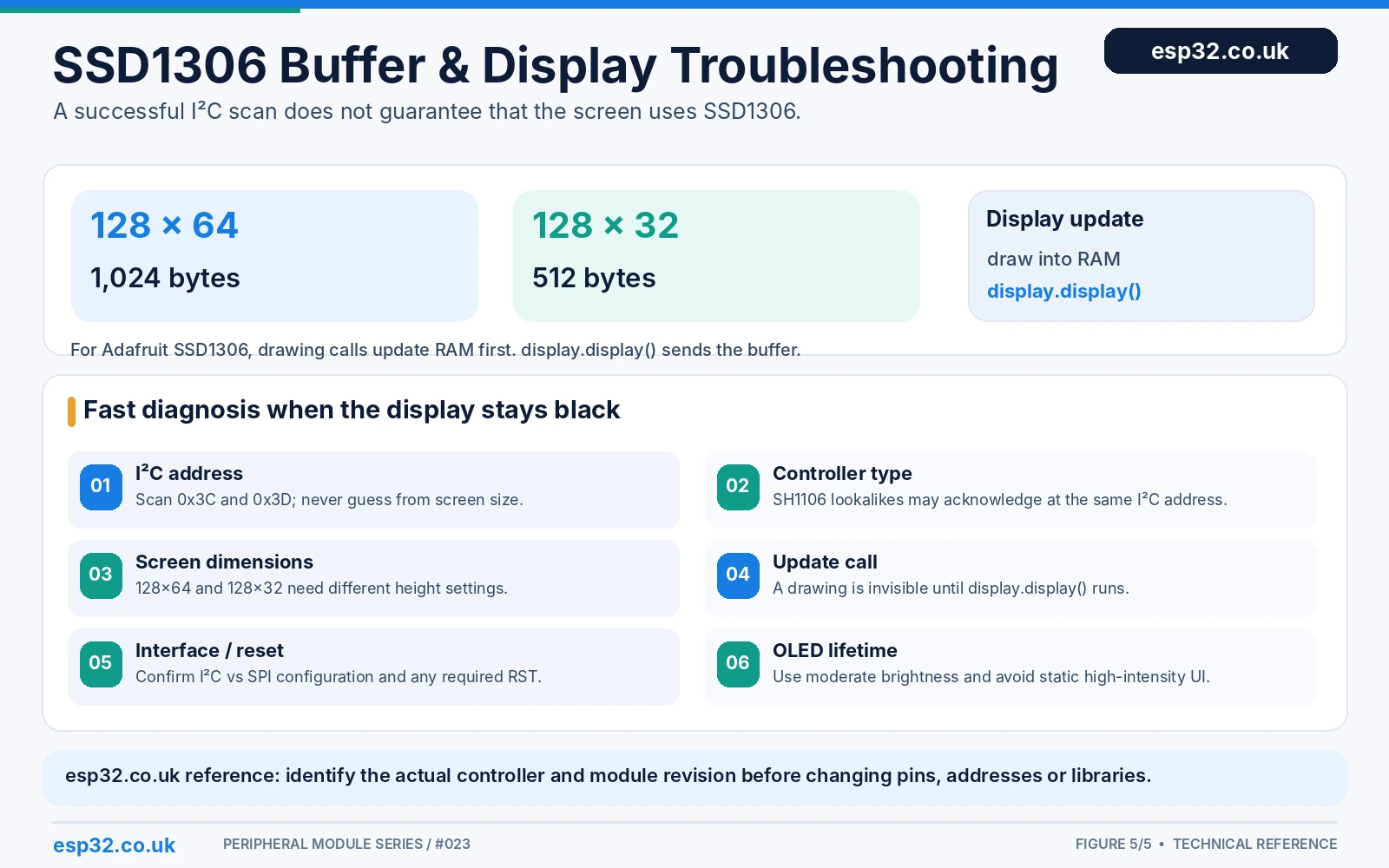
SSD1306 troubleshooting: black display, wrong dimensions and SH1106
| Symptom | Likely explanation or fix |
|---|---|
| No reply at 0x3C / 0x3D | Check ground, VCC polarity, SDA/SCL GPIO numbers, board I²C/SPI mode and pull-ups |
| Found 0x3C but screen blank | Code address mismatch, missing display() call, reset/configuration, or wrong controller |
| Pixels drawn outside screen | 128×32 versus 128×64 dimensions or incorrect text coordinates |
| Image shifted / corrupt columns | Display may use SH1106 instead of SSD1306; change library accordingly |
| SPI works poorly | Check D0 clock, D1 data, DC, CS and RST, plus Adafruit interface jumpers |
| Power rail drops | Check module rated supply and available 3.3 V regulator current |
| Screen flickers / intermittent errors | Cable length, excess I²C speed, low supply voltage or poor pull-up network |
| Scanner shows 0x78 / 0x7A in an example | These are 8-bit write-address representations; Arduino uses 0x3C / 0x3D |
| Multiple OLED screens mirror each other | They may have the same I²C address; change one if supported or isolate buses |
Why a SH1106 module can look identical
The SH1106 is a different monochrome OLED controller used in many similar-looking 1.3-inch modules. It can share the same physical I²C pin labels and address but has a different display memory mapping. Typical symptoms with the wrong library include a shifted image, blank columns or inconsistent rendering. Confirm the actual IC or seller datasheet, and try a matching SH1106 library (for example Adafruit SH110X or U8g2) rather than repeatedly swapping wires.
Frequently asked questions
Is SSD1306 always at I²C address 0x3C?
No. It supports both 0x3C and 0x3D. The module’s address resistor/jumper or factory configuration determines which is used. A scanner is more reliable than guessing from screen resolution.
Can I power a generic SSD1306 with 5 V on an ESP32?
Only if the exact board supports a 5 V input and provides suitable 3.3 V interface levels. A regulator on one manufacturer’s board does not establish the ratings of another. A verified 3.3 V module powered from ESP32 3V3 is the simplest safe starting point.
Are SDA and D1 the same signal?
Not necessarily. On a four-pin I²C board SDA is I²C data; on a seven-pin SPI board D1 (sometimes labelled SDA) is the SPI MOSI data input. Use the module’s supported bus and control pins.
Can I use two SSD1306 screens on one ESP32?
Yes, if they have distinct 7-bit I²C addresses 0x3C and 0x3D, or are on separate I²C buses or multiplexer channels. Each Adafruit display object needs its own framebuffer allocation. Shared reset behaviour should also be considered.
Why does Adafruit mention 0x3D for 128×64?
Some Adafruit example sketches and breakout revisions use 0x3D, while common generic 128×64 boards use 0x3C. The controller supports both addresses; resolution is not the address-selection mechanism.
References and further esp32.co.uk/ guides
- Adafruit monochrome OLED hardware and jumper guide
- Adafruit #326 0.96-inch 128×64 display
- Adafruit #938 1.3-inch 128×64 display
- Official Adafruit SSD1306 Arduino library
- Official Adafruit GFX Arduino library
- Adafruit SSD1306 API reference
- ESP32 I²C scanner guide
- TCA9548A multiplexer guide
Editorial verification: this esp32.co.uk/ article distinguishes generic four-pin I²C, generic seven-pin SPI, and Adafruit dual-interface designs. Do not transplant a physical pad order or solder-jumper diagram from one revision to another. The published library API was checked, but the examples have not been physically tested with every breakout. The five companion images will be wire-free and carry esp32.co.uk/ attribution.