
The DS3231PriceAliExpress price real-time clock (RTC) is a highly accurate timekeeping module that retains time while an ESP32 is powered down. It includes a temperature-compensated crystal oscillator (TCXO), two programmable alarms, a battery backup input and a fixed-address I²C interface. This guide compares the Adafruit DS3231 Precision RTC breakout (#5188/#3013) with the widely sold ZS-042 RTC modulePriceAliExpress price and explains how to connect either one to a 3.3 V ESP32.
Quick answer: for a classic ESP32-WROOM DevKit, connect 3V3 → VIN/VCC, GND → GND, GPIO21 → SDA and GPIO22 → SCL. The DS3231 uses the fixed 7-bit address 0x68. It has no RTC address solderPriceAliExpress price jumper. For an Arduino example, install Adafruit RTClib and use RTC_DS3231.
Battery safety: unlike the Adafruit breakout with a CR1220 primary coin-cell holder, some ZS-042 boards have a simple diode/resistor charging path. Do not insert a non-rechargeable CR2032 into an unverified ZS-042. Read the battery section below before assembling a backup-powered clock.
DS3231 capabilities and specifications
| Characteristic | Description |
|---|---|
| Clock | Year, month, date, weekday, hour, minute and second; automatic month and leap-year adjustment |
| Timekeeping accuracy | ±2 ppm at 0–40 °C under datasheet conditions (around 63 seconds per year) |
| Logic / supply | DS3231 VCC 2.3–5.5 V; use 3.3 V with an ESP32 to keep the I²C bus compatible |
| Backup supply | VBAT 2.3–5.5 V; coin-cell backup retains the clock when main supply disappears |
| I²C address | Fixed 0x68 in 7-bit Arduino notation; no address pins |
| I²C rate | Up to 400 kHz, subject to pull-up resistance and bus capacitance |
| Alarms | Alarm 1 has second resolution; Alarm 2 has minute resolution |
| Outputs | INT/SQW open-drain alarm or square wave; 32kHz open-drain reference output |
| Die temperature | Internal temperature measurement about ±3 °C, intended for oscillator compensation |
| Additional EEPROM | ZS-042 may include separate AT24C32, commonly at 0x57 |
The TCXO corrects oscillator frequency over temperature. The DS3231 remains a clock, not an Internet time source: it needs a valid time set initially and a functioning backup source. A Wi-Fi-connected ESP32 can periodically check NTP and update it, but NTP is not required for normal offline operation.
Adafruit DS3231 #5188 pinout
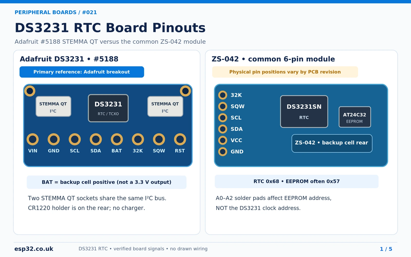
The Adafruit STEMMA QT version has eight labelled through-hole contacts: VIN, GND, SCL, SDA, BAT, 32K, SQW, RST. These names describe the breakout signals, not the 16 pins on the underlying chip. The older #3013 board has the same functional signals without STEMMA QT sockets. On the #5188, the two STEMMA QT connectors carry the same power and I²C bus.
| Marking | Purpose | ESP32 connection |
|---|---|---|
| VIN | Main board power input | ESP32 3V3 |
| GND | Shared reference | ESP32 GND |
| SCL | I²C clock, Adafruit 10 kΩ pull-up to VIN | GPIO22 on classic ESP32 |
| SDA | I²C data, Adafruit 10 kΩ pull-up to VIN | GPIO21 on classic ESP32 |
| BAT | Positive backup battery node | Normally unused; CR1220 holder already feeds VBAT |
| 32K | Open-drain 32.768 kHz clock reference | Optional input with proper pull-up |
| SQW | Open-drain square-wave or alarm output | Optional wake/interrupt input with 3.3 V pull-up |
| RST | Special power-fail/reset control | Leave unconnected for ordinary RTC use |
The BAT pin is not a 3.3 V power output for an ESP32. It is tied to the backup battery node. Adafruit does not charge the CR1220. When VCC is absent, the battery is intended to supply the tiny RTC timekeeping load, not a development board.
ZS-042 module: headers, AT24C32 and address pads
A common blue ZS-042 board has a six-pin group labelled 32K, SQW, SCL, SDA, VCC, GND. Many also expose a four-pin power/I²C header. The exact placement can differ with clone and PCB orientation; do not use an unlabelled photo as a universal mechanical pinout. The board usually contains a DS3231SN chip and a small AT24C32 EEPROM.
The DS3231 answers at 0x68 regardless of any pads marked A0, A1 or A2. Those pads typically set the separate AT24C32 EEPROM address, often from 0x50 to 0x57. Seeing both 0x68 and 0x57 in an I²C scanner usually indicates a single ZS-042 module with both devices present. The clock does not support solder-configurable addressing.
CR2032 charging hazard on ZS-042
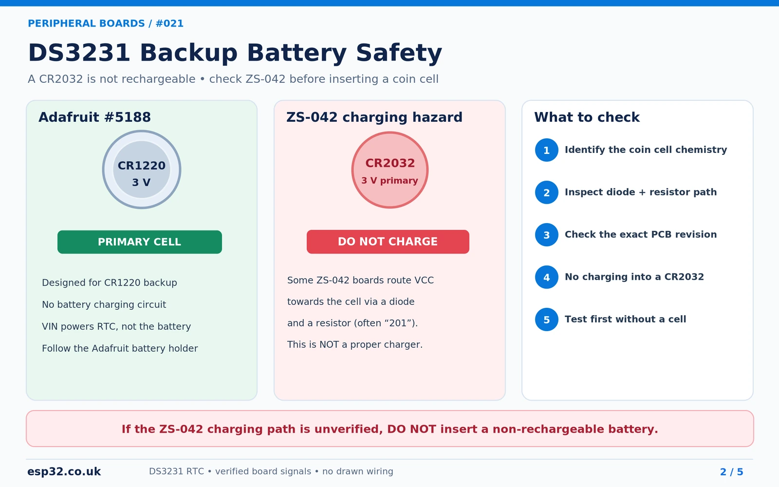
The CR2032 and CR1220 are normally non-rechargeable primary lithium batteries. The visually similar LIR2032 is a rechargeable lithium-ion cell, but it needs an appropriate charge controller. A cheap resistor and diode do not constitute a controlled Li-ion charging system.
A documented ZS-042 design uses a diode and a series resistor, often marked 201 (200 Ω), between main VCC and the coin-cell supply. With main power present, that network can attempt to charge an installed CR2032. Board revisions differ, and some omit the charger. Even running the module at 3.3 V does not prove the battery path is harmless under all conditions.
Safer procedure: initially test the ZS-042 at 3.3 V with no coin cell. Inspect its exact PCB and board schematic. If it contains a charging path, use a verified board modification that disconnects the charger from the battery without breaking the legitimate VBAT connection, or choose a documented RTC breakout intended for a non-rechargeable coin cell. Never randomly cut tracks, and disconnect all power and the coin cell before any soldering work.
DS3231 chip-level pinout and functional circuit
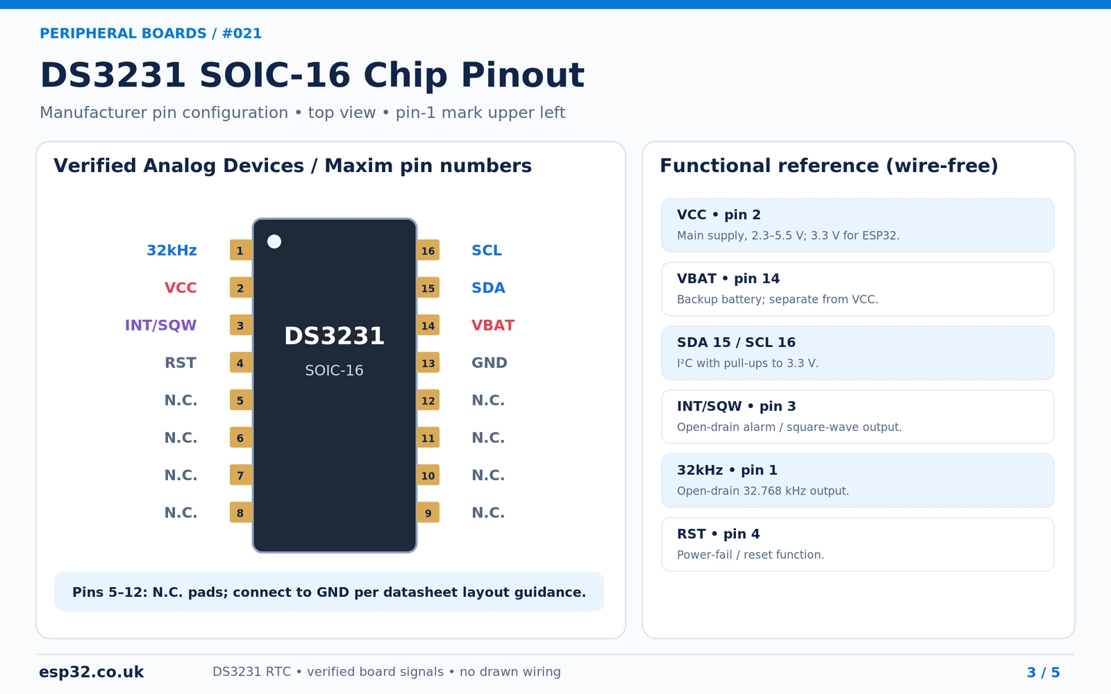
The original DS3231SN is a 16-lead SO package with a pin-1 dot. The manufacturer’s top view places pins 1–8 down the left edge and pins 16–9 down the right. The signal map is as follows:
| Pin | Signal | Function |
|---|---|---|
| 1 | 32kHz | Open-drain 32.768 kHz clock output |
| 2 | VCC | Main power supply, with close decoupling capacitor |
| 3 | INT/SQW | Open-drain interrupt or square-wave output |
| 4 | RST | Active-low reset/power-fail I/O |
| 5–12 | N.C. | Manufacturer says to connect these unused package pads to ground |
| 13 | GND | Ground |
| 14 | VBAT | Backup battery positive |
| 15 | SDA | I²C data |
| 16 | SCL | I²C clock |
The I²C lines require pull-ups to the microcontroller-compatible bus voltage; Adafruit supplies 10 kΩ resistors to VIN. INT/SQW and the 32kHz output are open-drain too, so suitable pull-ups are necessary if a microcontroller reads them. Neither output should be presented as a push-pull drive pin. The chip also provides power-fail logic through RST, which is not simply an arbitrary general-purpose reset output.
ESP32 to DS3231: exact four-wire connection table
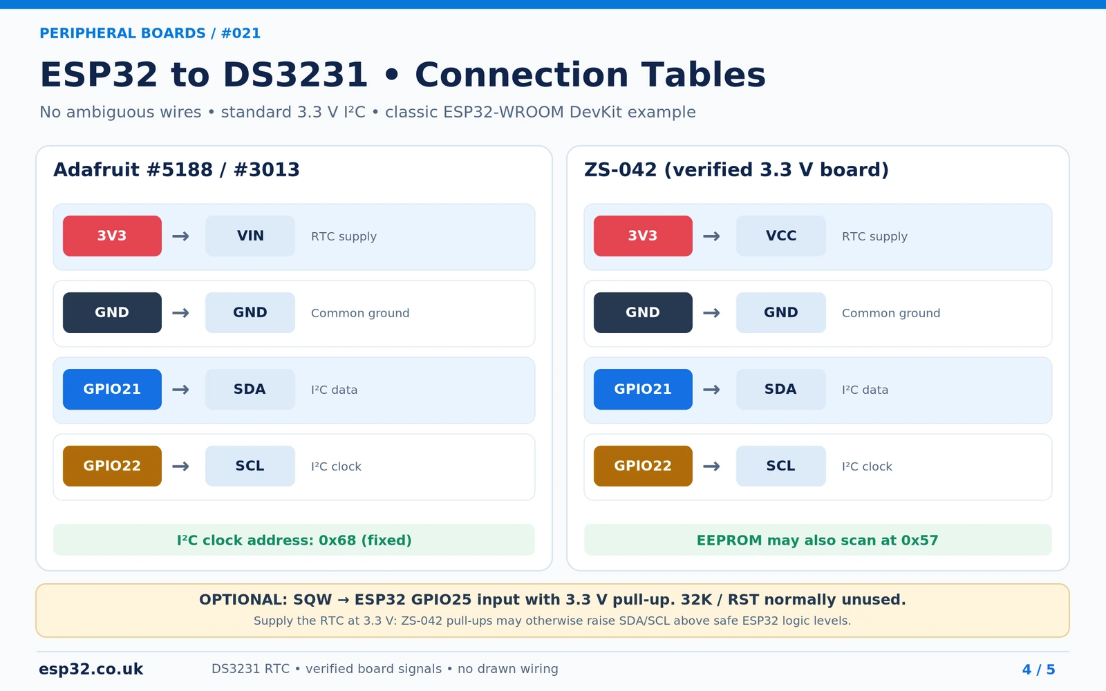
| ESP32 classic DevKit | Adafruit #5188/#3013 | ZS-042 | Signal |
|---|---|---|---|
| 3V3 | VIN | VCC | Power |
| GND | GND | GND | Common ground |
| GPIO21 | SDA | SDA | I²C data |
| GPIO22 | SCL | SCL | I²C clock |
| Optional GPIO25 | SQW | SQW | Interrupt with 3.3 V pull-up |
| Leave unconnected | 32K / RST | 32K | Not needed for simple timekeeping |
ESP32-C3, C6, S3 and other ESP32 versions may use different safe I²C pin selections. The example code explicitly sets 21 and 22; replace them with the correct pins for your hardware. For a ZS-042 board, supplying VCC at 5 V may also pull up SDA/SCL to 5 V, which is unsafe for directly connected ESP32 GPIOs. Keep the module and its I²C pull-ups in a verified 3.3 V domain.
Arduino IDE example: Adafruit RTClib
Install RTClib by Adafruit from Arduino IDE Library Manager. The library implements RTC_DS3231, including begin(), lostPower(), adjust(), now() and getTemperature(). This minimal example sets the clock from the PC’s compilation date and time only when the DS3231 reports the oscillator-stop flag.
#include <Arduino.h>
#include <Wire.h>
#include <RTClib.h>

RTC_DS3231 rtc;

void setup() {
  Serial.begin(115200);
  Wire.begin(21, 22);  // Classic ESP32-WROOM DevKit
  if (!rtc.begin(&Wire)) {
    Serial.println("DS3231 not found at 0x68");
    while (true) delay(1000);
  }
  if (rtc.lostPower()) {
    rtc.adjust(DateTime(F(__DATE__), F(__TIME__)));
    Serial.println("RTC set from sketch compile time");
  }
}

void loop() {
  DateTime t = rtc.now();
  Serial.printf("%04u-%02u-%02u %02u:%02u:%02u | %.2f C\n",
                unsigned(t.year()), unsigned(t.month()), unsigned(t.day()),
                unsigned(t.hour()), unsigned(t.minute()), unsigned(t.second()),
                rtc.getTemperature());
  delay(1000);
}
Compiler date/time can be wrong for the moment you upload, and RTC time has no timezone or daylight-saving information. For logging, consider storing UTC in the DS3231 and applying local timezone rules only when displaying timestamps. On an Internet-connected system you can set a verified time using NTP, but do not call adjust() every boot unless you intend to overwrite the stored clock.
Alarms, square-wave output and the oscillator-stop flag
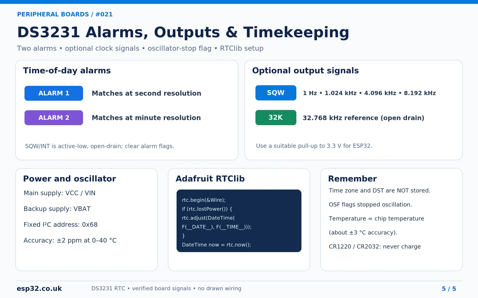
| Function | Usage |
|---|---|
| Alarm 1 | Can match seconds, minutes, hours and day/date, including second-resolution triggers |
| Alarm 2 | Matches minutes, hours and day/date; there is no seconds field |
| INT/SQW | Shared open-drain pin: active-low interrupt or selected square-wave frequency |
| Square-wave frequencies | 1 Hz, 1.024 kHz, 4.096 kHz and 8.192 kHz |
| 32K output | 32.768 kHz open-drain reference output, optional |
| OSF flag | Oscillator Stop Flag in status register 0x0F; checked through rtc.lostPower() |
| Temperature | Internal compensation reading, not precision room-temperature measurement |
For alarms, use the RTClib alarm API, clear the relevant alarm flag after handling it, and ensure INT/SQW has a compatible pull-up. If waking an ESP32 from deep sleep, choose a GPIO that your exact ESP32 model supports as a wake source. The DS3231 coin cell does not maintain power to the ESP32 itself.
Troubleshooting DS3231 modules
| Symptom | Checks |
|---|---|
| No 0x68 found | Confirm 3.3 V power, common ground, SDA/SCL orientation and ESP32 GPIO mapping. |
| 0x57 also appears | Likely a separate AT24C32 EEPROM on ZS-042, not a second RTC. |
| Clock loses time when disconnected | Coin cell missing, depleted, wrongly fitted or unsuitable charging path. |
| Clock resets to compilation time | Sketch may call rtc.adjust on every boot or OSF remains set. |
| One-hour error | UTC/local time or daylight-saving conversion, not oscillator drift. |
| SQW output stays low | Alarm flag not cleared, output mode misconfigured, or wrong pull-up. |
| RTC temperature differs from ambient | It measures internal IC temperature for oscillator compensation. |
DS3231 versus DS1307 and PCF8523
A DS1307 usually depends on an external tuning-fork crystal, and many older DS1307 breakouts are 5 V oriented. The DS3231 integrates its temperature-compensated oscillator and typically provides better long-term accuracy. The PCF8523 is another useful RTC for low-power projects, with a different oscillator architecture and accuracy trade-off. Choose based on required accuracy, power consumption, dimensions and backup-cell implementation.
Frequently asked questions
Can the DS3231 I²C address be changed?
No, the clock always uses 0x68 (7-bit). A0–A2 pads on a ZS-042 normally change its separate EEPROM address, not the clock address. To use multiple DS3231 devices independently, place them on different I²C segments or use a suitable multiplexer.
Is it safe to insert a CR2032 in a ZS-042 RTC module?
Only once you confirm the module will not attempt to charge a primary cell. Many versions have an unsuitable diode-and-resistor charging path; inspect and disable it safely or use a board with a documented non-charging backup holder.
Can I use the DS3231 without Wi-Fi?
Yes. Once set, it maintains time locally. The battery backup preserves it when main power is removed. Wi-Fi/NTP is useful for occasional accuracy checks but is not required for normal clock operation.
What is the difference between SQW and 32K?
SQW/INT can serve as an alarm interrupt or programmable square wave. The separate 32K pin is a nominal 32.768 kHz reference output. Both are open-drain and need suitable pull-ups if used.
Sources and technical references
- Analog Devices DS3231 datasheet — source for chip pinout, limits, alarms and registers.
- Adafruit DS3231 breakout guide — Adafruit #3013/#5188 pin functions and CR1220 backup.
- Adafruit #5188 — STEMMA QT board and current hardware details.
- Adafruit RTClib — Arduino library implementation and examples.
- ZS-042 battery-charging investigation — examples of unsafe charging networks on modules.
Editorial verification: The board pinouts and code were checked against manufacturer documentation but the sketch was not physically bench-tested. ZS-042 clones vary. All accompanying images use labelled boards and pin-connection tables rather than decorative wiring.