
The VL53L0XPriceAliExpress price is a miniature infrared time-of-flight (ToF) distance sensor. It measures the return of invisible 940 nm laser light instead of waiting for an ultrasonic echo and reports distance in millimetres over I²C. This practical hardware guide covers the Adafruit VL53L0XAliExpress price breakout (#3317), generic GY-VL53L0XAliExpress price modules, the XSHUT input, I²C address changes, safe ESP32 wiring, and a working Arduino IDE example using the official Adafruit library.
Quick answer: connect the Adafruit breakout VIN to ESP32 3V3, GND to GND, SDA to GPIO21 and SCL to GPIO22 on a classic ESP32-WROOM DevKit. Its default 7-bit I²C address is 0x29. You do not need XSHUT for one module; use independent XSHUT control when multiple modules need unique software-assigned addresses. The VL53L0X does not have a normal I²C-address solderPrice jumper.
This article complements the existing VL53L0X versus VL53L1X comparison on esp32.co.uk/. All five accompanying illustrations will use verified pinout labels and connection tables, without drawn wires.
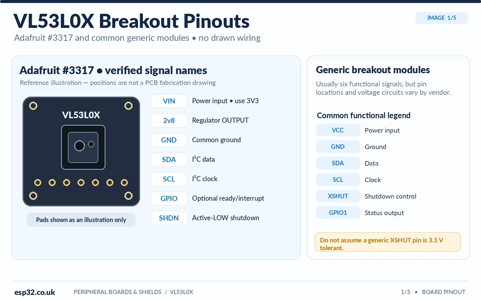
VL53L0X specifications at a glance
| Property | VL53L0X practical information |
|---|---|
| Technology | ST FlightSense, 940 nm VCSEL emitter and SPAD light detector |
| Range output | Distance in millimetres, with separate measurement status |
| Measuring distance | ST specifies operation up to 2 m in favourable conditions; Adafruit describes a practical 30–1000 mm breakout use case |
| Laser safety | Integrated Class 1 laser device when used in its intended configuration; never modify the emitter or optics |
| Digital interface | I²C, with 100 kHz a safe initial ESP32 test speed |
| Default address | 0x29 (7-bit); 0x52 is the corresponding 8-bit write address |
| Address selection | Software only; not retained after reset or power-off |
| XSHUT | Active-low hardware shutdown, useful for multiple devices |
| GPIO1 | Optional data-ready interrupt output |
| Adafruit supply | VIN accepts 3–5 V; onboard regulator provides a 2.8 V output |
| Raw sensor | Low-voltage silicon; not a 5 V-tolerant bare chip |
| Arduino library | Adafruit VL53L0X |
A “2 m maximum” should not be interpreted as a guarantee that every surface is reliably measured at that distance. Ambient infrared, target reflectance and angle, cover material, contaminants and timing configuration all affect the distance at which valid results are available. Start testing at about 100–500 mm with a clean, matte target.
Adafruit VL53L0X pinout and breakout differences
The Adafruit breakout supplies the circuitry a bare sensor lacks: voltage regulation and I²C level handling. The exact position of its pins can vary with breakout revisions; use the printed silkscreen on your board. Generic six-pin or smaller blue and purple carriers can share the VL53L0X chip while using different regulator, XSHUT and GPIO1 arrangements.
| Signal | Adafruit meaning | Connection on classic ESP32 |
|---|---|---|
| VIN | Power INPUT for Adafruit breakout, accepts 3–5 V | ESP32 3V3 |
| 2v8 | OUTPUT of onboard 2.8 V regulator, up to 100 mA according to Adafruit | Leave unconnected in normal setup |
| GND | Common ground | ESP32 GND |
| SDA | I²C data | ESP32 GPIO21 |
| SCL | I²C clock | ESP32 GPIO22 |
| GPIO / GPIO1 | Programmable data-ready or status interrupt; not level shifted on Adafruit board | Optional 3.3 V MCU GPIO after checking logic high |
| SHDN / XSHUT | Shutdown input: LOW disables sensor; Adafruit board pulls it HIGH and has a level-shifting diodePrice | Leave default for one sensor; dedicated GPIO for each sensor in multi-sensor design |
| STEMMA QT | I²C/power connectors on equipped board revisions | Optional compatible cable |
VIN is not 2v8. VIN is the Adafruit board’s power input and 2v8 is the regulator output. Do not inject 3.3 V or 5 V into 2v8. Also, GPIO1 is not level shifted on the Adafruit breakout; the sensor’s native logic level must be checked for the receiving microcontroller. The Adafruit SHDN circuit has its own protection arrangement; some generic modules expose the raw chip pin instead.
Can I use 5 V on the VL53L0X?
The Adafruit breakout VIN can accept up to 5 V as specified by Adafruit, but the bare VL53L0X chip and unprotected XSHUT/GPIO signals are not 5 V logic. When working with an ESP32, the simplest safe approach is to feed the breakout from 3V3 and use a 3.3 V-compatible I²C bus. For generic modules, confirm the actual board specification before connecting 5 V anywhere.
Default I²C address 0x29 and why there is no solder jumper
At power-up, every normal VL53L0X starts at 0x29 (7-bit). ST may describe this as 0x52 in 8-bit write-address notation. The Arduino Wire API and the Adafruit library use 0x29. Unlike a PCF8574 or ADS1115 module, VL53L0X address selection is performed by writing a device register in software rather than bridging an A0/A1 address pad.
The programmed address does not persist after power cycling. If two powered VL53L0X sensors both begin at 0x29, addressing one by itself is impossible until the other is held in hardware shutdown. The XSHUT procedure below is the standard solution; an I²C multiplexer is another option.
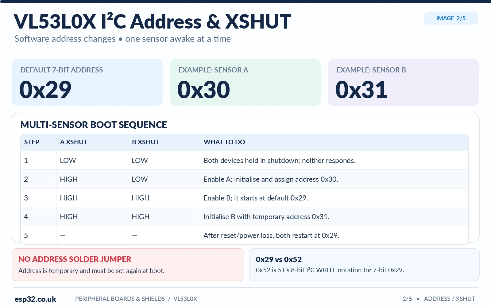
| Step | Sensor A XSHUT | Sensor B XSHUT | Action |
|---|---|---|---|
| Start | LOW | LOW | Both devices are held in shutdown |
| Enable A | HIGH | LOW | Only A appears at 0x29; initialise as 0x30 |
| Enable B | HIGH | HIGH | B appears at 0x29; initialise as 0x31 |
| Measure | HIGH | HIGH | Read A from 0x30 and B from 0x31 |
| Restart | LOW | LOW | Repeat; new addresses are not permanent |
Board-specific voltage warning: Adafruit’s SHDN breakout interface is designed for 3–5 V logic control. Some generic VL53L0X carriers expose a native, non-level-shifted XSHUT input. Do not force a 3.3 V push-pull HIGH level into an unverified lower-voltage chip pin. Use the board’s schematic, open-drain control or appropriate interface circuitry when necessary.
Functional reference: power, optical ranging and GPIO
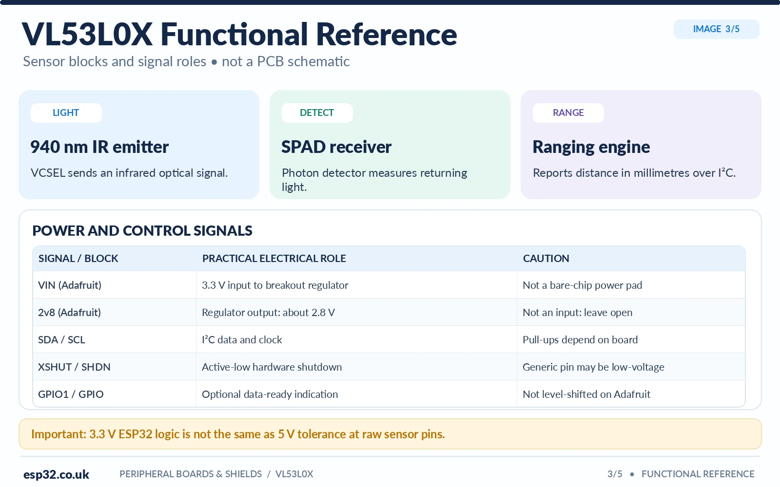
| Functional block | What it does |
|---|---|
| Optical emitter | A 940 nm VCSEL produces invisible light toward the target |
| Receiver | A SPAD array detects reflected photons; onboard processing estimates range |
| Board regulator | Adafruit breakout converts VIN into the sensor rail; 2v8 is an output |
| I²C level interface | Provides SDA/SCL communication, respecting the carrier board supply voltage |
| XSHUT input | Active-low reset/shutdown for controlled startup sequencing |
| GPIO1 output | Optional interrupt / measurement-ready status; separate from XSHUT |
| Electrical ground | All connected boards need a common GND reference |
Because several VL53L0X carrier boards exist, it is misleading to draw a single “universal” transistor/regulator schematic and claim every board is wired that way. An exact PCB schematic should be obtained from the particular manufacturer. The five technical images therefore show reliable functional labels and lookup tables rather than decorative electrical wires.
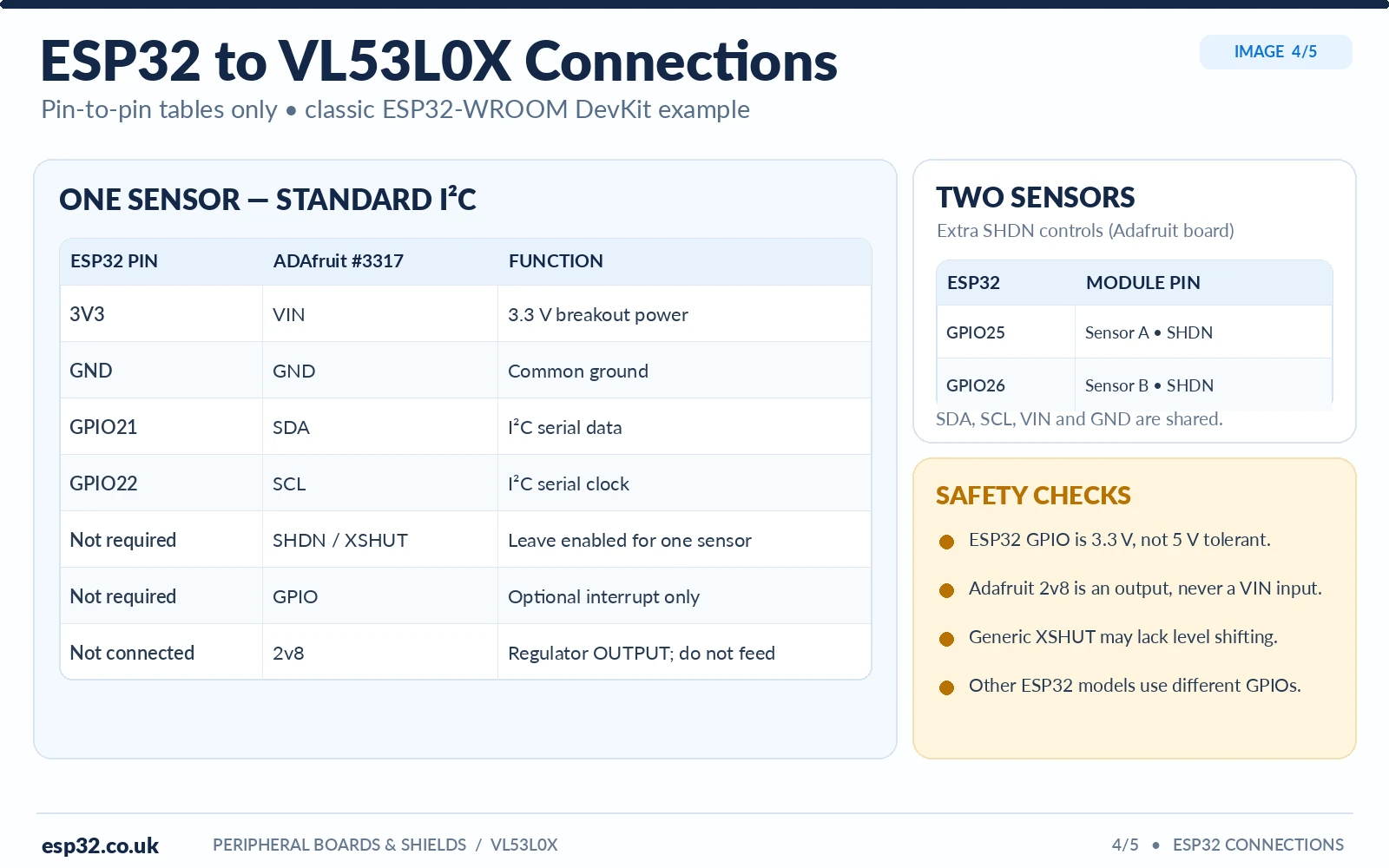
ESP32 connection table: one VL53L0X module
| ESP32 DevKit pin | Adafruit breakout pin | Note |
|---|---|---|
| 3V3 | VIN | Power the breakout, not the bare chip |
| GND | GND | Common supply reference |
| GPIO21 | SDA | I²C data |
| GPIO22 | SCL | I²C clock |
| Not connected | SHDN / XSHUT | Default pull-up enables a single sensor |
| Not connected | GPIO | Optional data-ready output |
| Not connected | 2v8 | This is a regulator OUTPUT, not an input |
GPIO21/GPIO22 are common I²C choices for classic ESP32-WROOM development boards; the ESP32-C3, C6, S3 and other variants can have different suitable pins. Make sure your sketch calls Wire.begin(SDA, SCL) with the GPIO numbers for the actual MCU, rather than copying a generic ESP32 picture.
Arduino IDE code using the Adafruit VL53L0X library
Open Arduino IDE, install the ESP32 board package if needed, then install Adafruit VL53L0X through Library Manager. Accept any dependencies requested. The sketch uses the library’s normal begin() and rangingTest() methods. Results are in millimetres, and invalid range status codes are not presented as genuine distances.
#include <Arduino.h>
#include <Wire.h>
#include <Adafruit_VL53L0X.h>

Adafruit_VL53L0X lox;

void setup() {
  Serial.begin(115200);
  delay(400);
  Wire.begin(21, 22);          // Classic ESP32 DevKit SDA/SCL
  Wire.setClock(100000);

  if (!lox.begin()) {          // Default 7-bit address: 0x29
    Serial.println("VL53L0X not detected. Check power and I2C pins.");
    while (true) delay(1000);
  }
  Serial.println("VL53L0X ready");
}

void loop() {
  VL53L0X_RangingMeasurementData_t reading;
  VL53L0X_Error err = lox.rangingTest(&reading, false);

  if (err == VL53L0X_ERROR_NONE && reading.RangeStatus == 0) {
    Serial.print("Distance: ");
    Serial.print(reading.RangeMilliMeter);
    Serial.println(" mm");
  } else {
    Serial.print("Invalid or out-of-range reading. Status: ");
    Serial.println(reading.RangeStatus);
  }
  delay(250);
}
This example checks RangeStatus == 0 for valid ranging. The basic Adafruit demonstration checks for status 4 (out of range), but printing other error status codes as actual millimetres could be misleading. A missing sensor causes begin() to fail; a sensor that responds but has poor optical conditions can still return invalid ranges. The code uses documented library API names and has not been physically bench-tested.
Illustrative Serial Monitor output
VL53L0X ready
Distance: 148 mm
Distance: 151 mm
Distance: 149 mm
Invalid or out-of-range reading. Status: 4
Serial Monitor must be set to 115200 baud. Test with a matte target at known distances and first remove the thin protective film on the sensor window. Treat these output numbers as examples, not measurements made for this article.
Two sensors: XSHUT configuration and Arduino example
For two verified Adafruit breakout boards, add one XSHUT wire per module. Both devices continue to share VIN, GND, SDA and SCL; use GPIO25 for A SHDN and GPIO26 for B SHDN on a classic ESP32-WROOM DevKit. Other ESP32 variants or unprotected generic SHDN signals require their own pin/voltage review.
#include <Arduino.h>
#include <Wire.h>
#include <Adafruit_VL53L0X.h>

constexpr int XSHUT_A = 25;
constexpr int XSHUT_B = 26;
Adafruit_VL53L0X a, b;

void setup() {
  Serial.begin(115200);
  Wire.begin(21, 22);
  pinMode(XSHUT_A, OUTPUT);
  pinMode(XSHUT_B, OUTPUT);
  digitalWrite(XSHUT_A, LOW);
  digitalWrite(XSHUT_B, LOW);
  delay(20);

  digitalWrite(XSHUT_A, HIGH);
  delay(20);
  if (!a.begin(0x30)) {
    Serial.println("Sensor A failed");
    while (true) delay(1000);
  }
  digitalWrite(XSHUT_B, HIGH);
  delay(20);
  if (!b.begin(0x31)) {
    Serial.println("Sensor B failed");
    while (true) delay(1000);
  }
  Serial.println("Sensors at 0x30 and 0x31");
}

void report(const char* name, Adafruit_VL53L0X& sensor) {
  VL53L0X_RangingMeasurementData_t r;
  if (sensor.rangingTest(&r, false) == VL53L0X_ERROR_NONE &&
      r.RangeStatus == 0) {
    Serial.printf("%s: %u mm  ", name, (unsigned)r.RangeMilliMeter);
  } else {
    Serial.printf("%s: invalid  ", name);
  }
}

void loop() {
  report("A", a);
  report("B", b);
  Serial.println();
  delay(300);
}
The Adafruit library’s begin(new_address) configures a sensor at the specified runtime address. A reset returns both sensors to 0x29, so the XSHUT sequence must run each time. If you cannot independently disable two sensors, an I²C multiplexer such as the TCA9548A is a practical alternative.
Range, accuracy and common troubleshooting
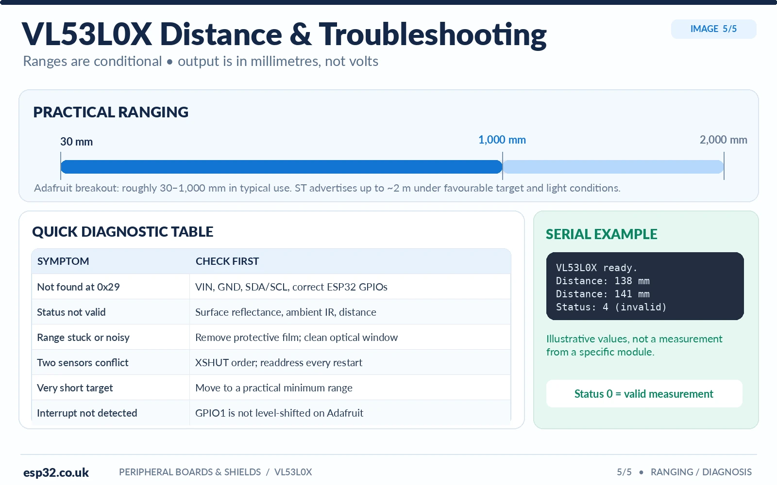
| Symptom | Cause and recommended check |
|---|---|
| No sensor at 0x29 | Check VIN, GND, SDA/SCL, selected ESP32 GPIOs, I²C 100 kHz and XSHUT not held LOW. |
| Two sensors collide | Both boot at 0x29; use independent XSHUT control and new runtime addresses. |
| All measurements invalid | Remove optical film, use matte target, reduce ambient IR and check optical window. |
| Only short distances work | Reflectance, ambient light, angle and timing affect usable range; 2 m is not guaranteed. |
| XSHUT damages or fails on generic module | Verify the raw pin logic level; some carrier boards do not shift XSHUT. |
| Very close target fails | Operation at a few millimetres is beyond many practical module use cases. |
| Incorrect reading through plastic | Cover-glass reflections and IR absorption can cause crosstalk; test the material. |
| GPIO1 unreadable | Check that the signal is an unshifted low-voltage output and whether interrupt is configured. |
VL53L0X versus an ultrasonic HC-SR04
A ToF sensor usually has a much narrower optical measurement area than an ultrasonic transmitter, which can be useful for small target detection. Ultrasonic sensing can be better for some objects that reflect little near-infrared light and for some tank geometries. Optical ranging also needs an unobstructed, suitable optical path. Neither technology is universally more accurate in all environments.
Frequently asked questions
Is the VL53L0X address 0x29 or 0x52?
Use 0x29 with Arduino as the 7-bit I²C address. 0x52 is the corresponding 8-bit write address shown in some ST documents; they refer to the same device.
Is there an I²C address jumper on a VL53L0X?
Not in the usual way. Runtime software assigns the new address, and the sensor reverts to 0x29 on reset. A manufacturer may expose other configuration pads on a carrier, but do not confuse them with a permanent address selector.
Can I use XSHUT to switch multiple sensors?
Yes. Hold all but one sensor inactive, assign a new address to the active device, then enable and configure the next. Ensure the control signal levels suit the particular carrier board.
Can a VL53L0X measure through a tank wall?
Not reliably by assumption. Plastic transmission, reflections and cover-glass crosstalk vary, and many opaque walls block the 940 nm light. For liquid-level use, test the exact material or select a different sensor technology.
What is the difference between XSHUT and GPIO1?
XSHUT is the active-low shutdown input. GPIO1 is a programmable interrupt or data-ready output. They are not interchangeable, and generic boards may expose them at different voltage levels.
References and further reading
- Adafruit VL53L0X breakout pinouts — breakout voltage and signal descriptions.
- Adafruit VL53L0X Arduino guide — startup, sensor ranges and multiple-device setup.
- Official Adafruit VL53L0X library — code and method definitions.
- ST VL53L0X product reference — optical sensor specification and safety.
- ST VL53L0X datasheet — native sensor pins and electrical parameters.
- VL53L0X versus VL53L1X — existing site comparison.
Editorial accuracy: The connection tables refer to Adafruit breakout functions and an example classic ESP32-WROOM board. Generic variants can differ in regulator design, pin placement, and raw XSHUT/GPIO levels. The example code was checked against the Adafruit library API; it was not physically bench-tested. Image generation is a separate job and must use wire-free verified pinouts and tables.