
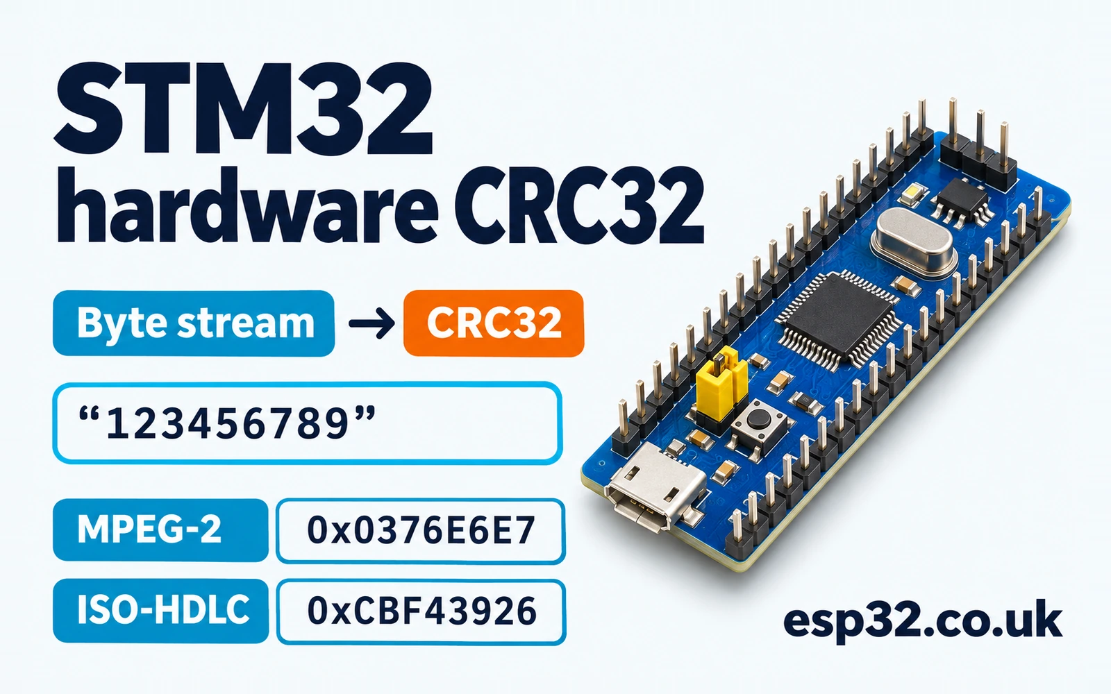
The STM32F103C8PriceAliExpress price Blue PillPriceAliExpress price has a hardware CRC unit, but sending four bytes to it as a native integer can give a different result from sending the same four bytes to a desktop CRC tool. The F1 unit consumes whole words in a fixed bit order. To match a byte-oriented protocol, you need to agree on the CRC parameters, pack the words in stream order and handle any final bytes.
In this esp32PriceAliExpress price.co.uk/ guide, you'll use the STM32Cube HAL to calculate CRC-32/MPEG-2 and CRC-32/ISO-HDLC on the same message. The second profile matches the CRC returned by zlib. The lab verifies both profiles with the nine ASCII bytes in 123456789 and checks a small binary frame with a little-endian checksum field.
Quick answer. Enable CRC in CubeMX and check its AHB clock. On the F103, a reset seeds the CRC at 0xFFFFFFFF and the unit uses polynomial 0x04C11DB7 with 32-bit, MSB-first word input. For a non-reflected byte stream, place the first byte in bits 31–24. For ISO-HDLC, reflect each input byte, then reflect the final state and XOR it with 0xFFFFFFFF. Process a final one to three bytes in software so the protected message length stays exact.
Know what the STM32F103 CRC unit calculates
The CRC peripheral has a running 32-bit state. A write to CRC_DR feeds one word and updates that state. A read of the same register returns the current state. Setting the RESET bit in CRC_CR puts the state back to all ones. The separate eight-bit CRC_IDR register is general-purpose storage and has no role in the calculation.
| STM32F103 feature | Behaviour in this lab |
|---|---|
| CRC clock | Enabled through RCC on the AHB bus |
| Generator polynomial | Fixed 0x04C11DB7 |
| Reset seed | Fixed 0xFFFFFFFF |
| Data feed | One 32-bit word per write, most significant bit first |
| Input and output reflection | Implemented in software when needed |
| Final XOR | Implemented by the chosen profile |
| Arbitrary byte lengths | Complete groups go through hardware. Up to three final bytes use the same recurrence in software |
This lab targets the STM32F103 peripheral. Other STM32 families can offer selectable polynomial, seed, reflection or byte input. Check the reference manual for the exact part before reusing a peripheral configuration from another family. A wider or more configurable CRC unit may let you express the same protocol with different HAL settings. STM32 families and peripheral differences
CRC is a check for accidental corruption. The sender and receiver agree on the protected bytes, calculate a value and compare it with the stored or transmitted value. The calculation is public and a party able to change the message can also change its CRC. Use an authenticated protocol when the receiver needs to establish who produced the message.
Match all of the CRC parameters
A polynomial name alone leaves out how the bits enter the calculation and how the result is presented. Two common 32-bit profiles use the same polynomial and seed but give different results for the same bytes. Agree on the width, polynomial, initial state, input reflection, output reflection and final XOR.
| Parameter | CRC-32/MPEG-2 | CRC-32/ISO-HDLC, zlib-compatible |
|---|---|---|
| Width | 32 | 32 |
| Polynomial in normal notation | 0x04C11DB7 | 0x04C11DB7 |
| Initial state | 0xFFFFFFFF | 0xFFFFFFFF |
| Reflect each input byte | No | Yes |
| Reflect final result | No | Yes |
| Final XOR | 0x00000000 | 0xFFFFFFFF |
| Check value for ASCII 123456789 | 0x0376E6E7 | 0xCBF43926 |
Some software implementations of ISO-HDLC use the reflected polynomial representation 0xEDB88320 and shift right. The code here keeps the F103’s MSB-first recurrence, reflects the incoming bytes and transforms the result once at the end. These are two ways to compute the same profile. When comparing against zlib, use its normal checksum API. The internal seed in the table is part of the profile. The library exposes its own convention for starting and continuing a checksum.
The standard check message is the nine ASCII bytes 31 32 33 34 35 36 37 38 39 in hexadecimal. A C string literal occupies a tenth byte for its terminating zero. Pass sizeof text - 1 when the protocol protects just the characters. If you include a newline or a terminal zero, you’ve changed the input message.
Enable CRC and check the first two words
Use a Blue Pill with a working SWD connection. Create an STM32F103C8 project, keep Serial Wire debugging and enable the CRC peripheral in CubeMX. This lab needs no CRC signal pins. Keep the generated MX_CRC_Init() call and verify that the HAL MSP initialiser enables the CRC clock with __HAL_RCC_CRC_CLK_ENABLE(). The exact location of the generated function can vary with the project layout. STM32CubeMX and STM32CubeIDE setup
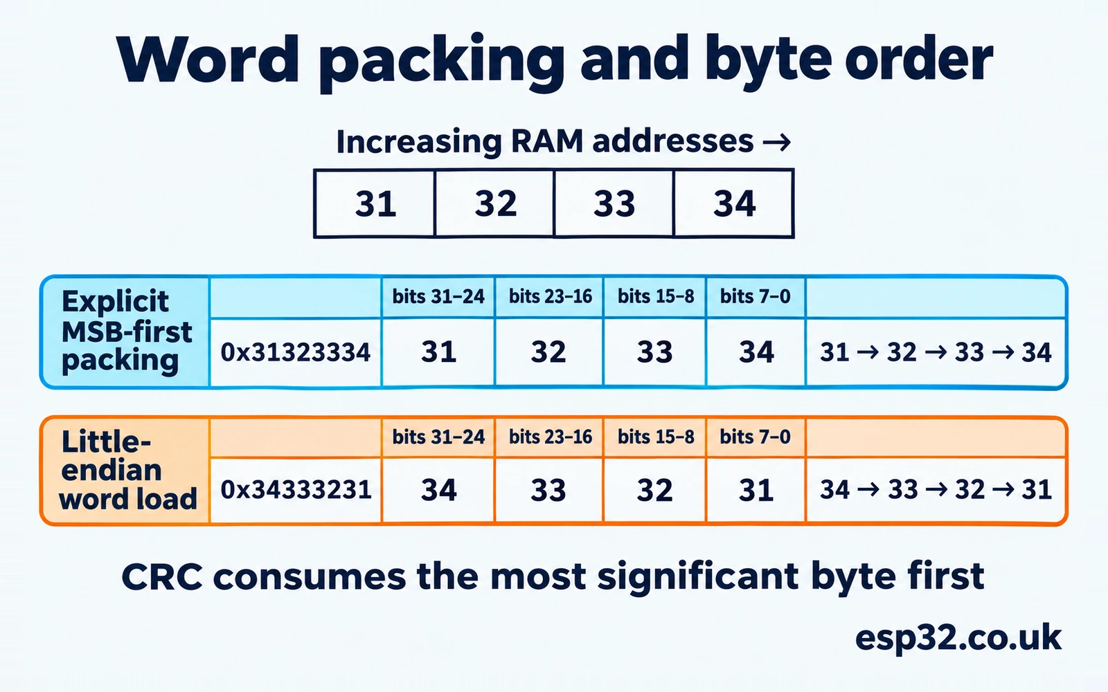
The hardware feed width is 32 bits. The first byte of an MSB-first stream belongs in bits 31–24, the next in bits 23–16 and so on. For example, write the value 0x31323334 to feed ASCII 1234 in that order. The second group 5678 becomes 0x35363738.
| Input sequence | First 32-bit word | Second 32-bit word | Raw result after two words |
|---|---|---|---|
| Explicit MSB-first packing of ASCII 12345678 | 0x31323334 | 0x35363738 | 0x49E3C2FB |
| Native little-endian loads of the same byte groups | 0x34333231 | 0x38373635 | 0xFEFC54F9 |
A native little-endian load puts the first byte of the group in the lowest eight bits. If you feed that integer to the CRC, each group is processed in reversed byte order. Alignment is a separate issue. Casting an arbitrary byte-buffer pointer to uint32_t * can also break alignment or the C object access rules. Assemble the word with shifts from byte reads so the order is explicit and the input can start at any byte address.
Decide whether to reset or continue
HAL_CRC_Calculate() resets the unit before feeding the supplied words. HAL_CRC_Accumulate() starts from the state already in the peripheral. On this HAL driver both lengths are counts of uint32_t words. Passing sizeof words for a two-word array supplies the byte count eight and asks the function to read eight words. Use a word count derived from the array or the number of staged words.
Try these three statements after MX_CRC_Init(). Save the values for the debugger or inspect the calls in order. words is a writable array because the STM32F1 HAL signature takes a non-const pointer, even though the driver only reads the input.
uint32_t words[] = {0x31323334U, 0x35363738U};
uint32_t prefix = HAL_CRC_Calculate(&hcrc, words, 1U);
uint32_t continued = HAL_CRC_Accumulate(&hcrc, words + 1, 1U);
uint32_t independent = HAL_CRC_Calculate(&hcrc, words + 1, 1U);| Variable | Bytes represented | Expected raw state |
|---|---|---|
| prefix | 1234 | 0xA695C4AA |
| continued | 12345678 | 0x49E3C2FB |
| independent | 5678 | 0xAD2A807E |
The three values let you check reset behaviour without any reflection or partial words. Running another calculation between the first two calls would change the state used by the second. A copied handle still points to the same CRC registers. Give one execution context exclusive access from reset through the final read. If several tasks need checksums, assign a worker or hold one lock around the complete calculation. A status check at entry is useful for diagnostics and does not reserve the peripheral.
The STM32F103 reference manual describes a fixed reset seed. Some comments in the generic HAL source mention an initial-value register. Use the F1 register layout and the actual reset macro for this part. The HAL source shows that the reset sets the control bit and then feeds complete 32-bit words.
Inspect the peripheral before changing the code
In the debugger, confirm that the CRC enable bit in RCC_AHBENR is set after the MSP initialisation. The HAL handle can say Ready while a later clock change has gated the peripheral, so inspect both when a call fails. At the reset step, CRC_DR should read 0xFFFFFFFF before the first word. The RESET bit clears itself, so a later read of the control register will not retain evidence that a reset occurred. A breakpoint just after the reset and one after the first word make those two states easy to distinguish.
Process the last bytes and reflect the stream
The nine-byte check message has two complete words and one byte left. After the hardware has processed 12345678, the non-reflected state is 0x49E3C2FB. To feed the final byte 0x39, XOR it into the top eight bits, yielding 0x70E3C2FB. Apply eight MSB-first shifts, XORing polynomial 0x04C11DB7 whenever the previous top bit was set. The result is 0x0376E6E7. This is the same recurrence used for a byte within a full word.
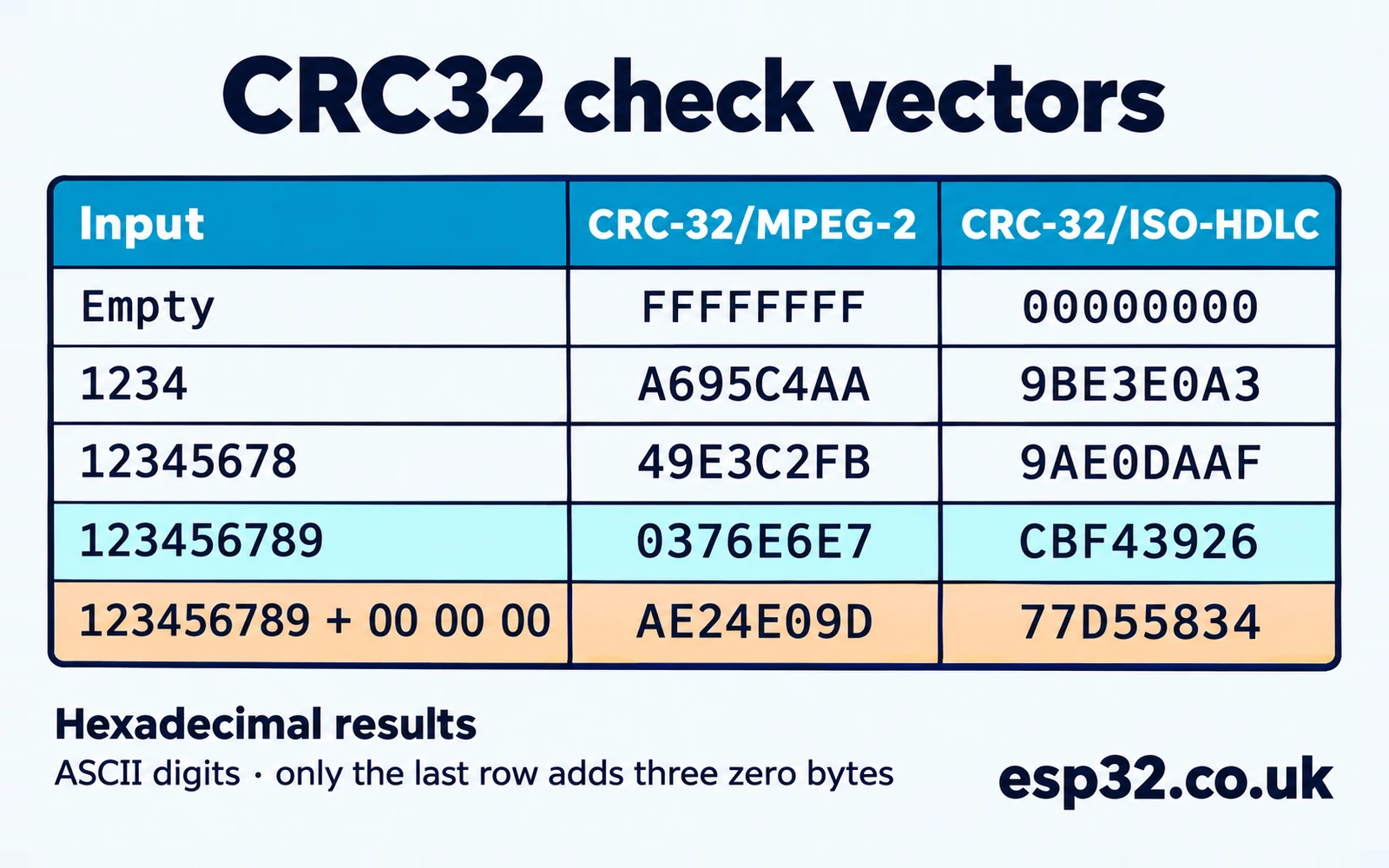
If you fill the last word with zeros, you calculate the checksum of a longer message. For the check string followed by three zero bytes, the MPEG-2 result becomes 0xAE24E09D and the ISO-HDLC result becomes 0x77D55834. A protocol may specify padding and include those bytes in its CRC. The lab protects the exact message length and adds no padding.
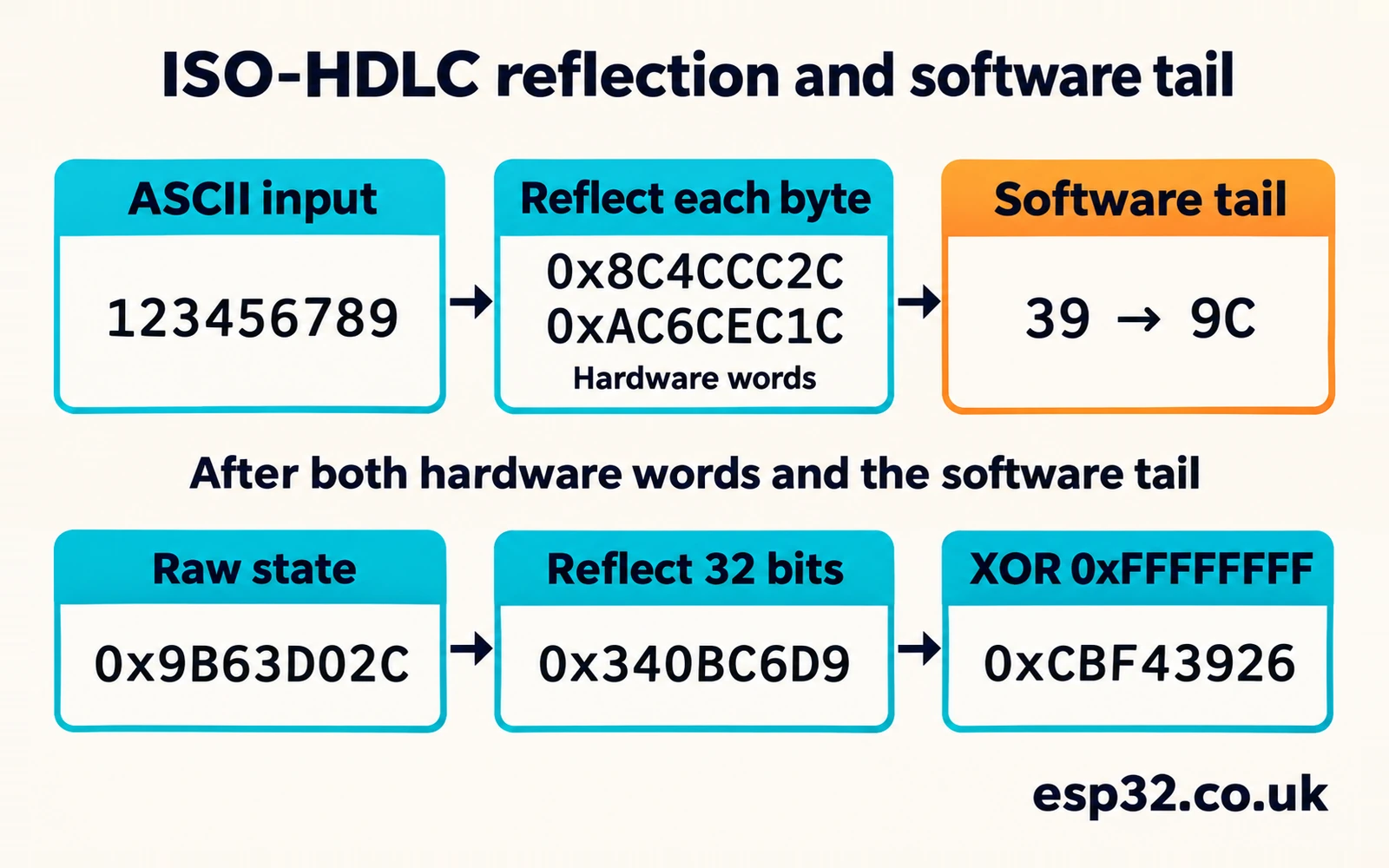
For ISO-HDLC, reflect the bits in each byte while keeping the byte sequence in its original order. For the first four bytes, 0x31323334 becomes 0x8C4CCC2C. On Cortex-M3, __RBIT() reflects a 32-bit integer and also reverses the positions of its bytes. Applying __REV() afterwards restores the byte positions. For the final byte 0x39, reflecting its eight bits yields 0x9C.
Apply the same tail recurrence to the reflected byte. After all nine bytes have been processed, the MSB-first state for this transformed input is 0x9B63D02C. Reflect the full state to get 0x340BC6D9, then apply the final XOR to get 0xCBF43926. The two reflections serve different roles. One changes how each input byte enters the recurrence. The other changes the orientation of the final 32-bit result.
Preserve the state until the entire message is ready
For a long input, the code stages up to eight words at a time. Each call to HAL_CRC_Accumulate() continues the same hardware state. The extra staging space is eight times four bytes, or 32 bytes. The final partial group remains a local software state. Once the software tail has been applied, reading CRC_DR gives the state of the complete-word prefix only. Read the value returned by the lab function for the finished checksum.
If data arrives in fragments, keep up to three pending bytes until the next fragment supplies a whole word. A fragment boundary can fall in the middle of a CRC word. Padding and resetting at each boundary changes the protected input. Apply any final reflection and XOR after the whole message, then start a separate checksum with a reset for the next message. For this lab, collect a complete buffer first so one call owns the whole calculation.
Trace a split that crosses the word boundary
Suppose a transport delivers the check string in three fragments, 123, 45 and 6789. The first fragment leaves three bytes waiting. The first byte of the second fragment completes the word for 1234. The other byte, 5, stays pending. The third fragment supplies enough bytes for 5678 and leaves 9 for the final software step. The message is still nine bytes long.
| Fragment | Complete word available at this point | Pending after the word feed |
|---|---|---|
| 123 | None | 123 |
| 45 | 0x31323334 | 5 |
| 6789 | 0x35363738 | 9 |
| End of message | None | Finish byte 0x39 in software |
This table uses the non-reflected packing to make the bytes visible. The reflected profile would transform each completed word before feeding it and reflect the pending byte before stepping the tail. The rule about where the groups fall is identical. A fragment with no complete word can arrive and leave the hardware state unchanged. If the message ends there, those pending bytes still contribute to the result.
In a streaming design that holds the hardware across fragments, the owner also has to deal with an abandoned frame. Reset the state and discard any pending bytes before a new frame begins. If fragments arrive from multiple sources, track which frame owns the peripheral state. The supplied single-buffer API makes that ownership interval the duration of one call.
Add the CRC lab to the HAL project
Copy crc_lab.h and crc_lab.c into the generated project and compile as C11. Call the lab after MX_CRC_Init(). It checks that the handle targets CRC, that the RCC clock is enabled and that the handle is ready. It also checks the profile and pointers. Pass NULL for the input only when length is zero. An invalid call returns false without changing the result variable. This keeps the validity of the operation separate from the checksum itself, since zero is a valid CRC value.
#ifndef STM32_038_CRC_LAB_H
#define STM32_038_CRC_LAB_H

#include "stm32f1xx_hal.h"
#include <stdbool.h>
#include <stddef.h>
#include <stdint.h>

typedef enum {
    CRC_LAB_MPEG2,
    CRC_LAB_IEEE
} CrcLabProfile;

bool CrcLab_Calculate(CRC_HandleTypeDef *handle, const uint8_t *data, size_t length,
                      CrcLabProfile profile, uint32_t *result);
bool CrcLab_CheckFrame(CRC_HandleTypeDef *handle, const uint8_t *frame, size_t frame_size);

#endif
#include "crc_lab.h"
enum { WORD_BYTES = 4, BATCH_WORDS = 8, MAX_PAYLOAD_BYTES = 32 };
static uint32_t pack_msb_first(const uint8_t *bytes)
{
return ((uint32_t)bytes[0] << 24) | ((uint32_t)bytes[1] << 16) |
((uint32_t)bytes[2] << 8) | (uint32_t)bytes[3];
}
static uint32_t step_msb_first(uint32_t state, uint8_t byte)
{
state ^= (uint32_t)byte << 24;
for (unsigned bit = 0; bit < 8; ++bit) {
uint32_t polynomial = (state & UINT32_C(0x80000000)) ? UINT32_C(0x04C11DB7) : 0U;
state = (state << 1) ^ polynomial;
}
return state;
}
bool CrcLab_Calculate(CRC_HandleTypeDef *handle, const uint8_t *data, size_t length,
CrcLabProfile profile, uint32_t *result)
{
if (handle == NULL || handle->Instance != CRC || result == NULL ||
(data == NULL && length != 0U) ||
(profile != CRC_LAB_MPEG2 && profile != CRC_LAB_IEEE) ||
!__HAL_RCC_CRC_IS_CLK_ENABLED() || HAL_CRC_GetState(handle) != HAL_CRC_STATE_READY) {
return false;
}
const bool reflected = profile == CRC_LAB_IEEE;
__HAL_CRC_DR_RESET(handle);
uint32_t state = UINT32_MAX;
uint32_t words[BATCH_WORDS];
while (length >= WORD_BYTES) {
size_t available = length / WORD_BYTES;
uint32_t count = available > BATCH_WORDS ? BATCH_WORDS : (uint32_t)available;
for (uint32_t i = 0; i < count; ++i) {
uint32_t word = pack_msb_first(data);
/* RBIT reverses all bits. REV then restores the byte order. */
words[i] = reflected ? __REV(__RBIT(word)) : word;
data += WORD_BYTES;
}
state = HAL_CRC_Accumulate(handle, words, count);
length -= WORD_BYTES * count;
}
while (length != 0U) {
uint8_t byte = *data++;
if (reflected) {
byte = (uint8_t)(__RBIT((uint32_t)byte) >> 24);
}
state = step_msb_first(state, byte);
--length;
}
*result = reflected ? (__RBIT(state) ^ UINT32_MAX) : state;
return true;
}
bool CrcLab_CheckFrame(CRC_HandleTypeDef *handle, const uint8_t *frame, size_t frame_size)
{
if (frame == NULL || frame_size < 6U || frame[0] != 1U ||
frame[1] > MAX_PAYLOAD_BYTES || frame_size != 6U + frame[1]) {
return false;
}
size_t protected_size = frame_size - 4U;
const uint8_t *wire = frame + protected_size;
uint32_t received = (uint32_t)wire[0] | ((uint32_t)wire[1] << 8) |
((uint32_t)wire[2] << 16) | ((uint32_t)wire[3] << 24);
uint32_t computed;
return CrcLab_Calculate(handle, frame, protected_size, CRC_LAB_IEEE, &computed) &&
computed == received;
}Each calculation resets the hardware before it starts. The function reads complete groups from the byte buffer and stages them in an aligned word array for the HAL. There is no alignment requirement on the caller’s byte pointer. The function leaves the input bytes unchanged. A buffer shorter than four bytes is calculated entirely in the software tail after the reset. An empty message produces the seed after applying the requested final transformation.
Run the check string through both profiles
In the generated main.c, add the include to the user include section and put the three volatile diagnostics in the global user section. Place the calculation in the user section after the generated initialisation. Use local non-volatile variables for the two output pointers, then copy their values into the debugger diagnostics.
/* USER CODE Includes */
#include "crc_lab.h"

/* USER CODE PV */
volatile uint32_t crc_mpeg2_result, crc_ieee_result;
volatile bool crc_checks_ok;

/* USER CODE 2, after MX_CRC_Init() */
static const uint8_t text[] = "123456789";
uint32_t mpeg2, ieee;
if (CrcLab_Calculate(&hcrc, text, sizeof text - 1U, CRC_LAB_MPEG2, &mpeg2) &&
    CrcLab_Calculate(&hcrc, text, sizeof text - 1U, CRC_LAB_IEEE, &ieee)) {
    crc_mpeg2_result = mpeg2;
    crc_ieee_result = ieee;
    crc_checks_ok = mpeg2 == UINT32_C(0x0376E6E7) && ieee == UINT32_C(0xCBF43926);
}
Flash over SWD and let the code execute. Watch crc_checks_ok and the two result fields. Use hexadecimal display so the values can be compared directly with the table. If the flag is false, step through the calculation and check its boolean return before interpreting the saved numbers. At a reset, the debugger diagnostics start at zero, which can otherwise look like an actual checksum result. STM32CubeProgrammer and SWD flashing guide
| Message bytes | MPEG-2 expected | ISO-HDLC expected |
|---|---|---|
| Empty | 0xFFFFFFFF | 0x00000000 |
| ASCII 1234 | 0xA695C4AA | 0x9BE3E0A3 |
| ASCII 12345678 | 0x49E3C2FB | 0x9AE0DAAF |
| ASCII 123456789 | 0x0376E6E7 | 0xCBF43926 |
| ASCII 123456789 followed by three zero bytes | 0xAE24E09D | 0x77D55834 |
The two-word test isolates packing and the reset policy. The nine-byte test adds the tail. If the CRC matches for the first eight bytes but fails for the ninth, inspect the byte count and the tail before changing the polynomial. Check whether a desktop tool interprets your input as typed text or binary hex. The text 31 32 is five ASCII bytes, while a hex decoder turns it into the two bytes for 12.
The code compiled and linked for Cortex-M3 with ST’s startup and CRC driver. A native C test linked the same lab code to a mock MSB-first hardware engine and compared 1,040 results for four starting offsets, lengths zero through 129 and both profiles. It checked the number of complete words sent to the peripheral as well as the final result. The board test checks the real CRC register path and project configuration.
Protect a small binary frame
Use the checksum over a clearly defined byte range. This example frame consists of a version byte, a payload length, zero through 32 payload bytes and a four-byte ISO-HDLC checksum. The length counts the payload only. The checksum covers version, length and payload in that order. It is stored least significant byte first at the end of the frame.
| Field | Example bytes | Included in the CRC |
|---|---|---|
| Version | 01 | Yes |
| Payload length | 03 | Yes |
| Payload | 00 80 FF | Yes |
| CRC field | 85 06 76 FF | Separate comparison field |
For the five protected bytes 01 03 00 80 FF, the CRC is 0xFF760685. The transmitted order for the four CRC bytes is 85 06 76 FF. That serialization rule is separate from bit reflection and from the word value written to the peripheral. A protocol can choose big-endian serialization for the same computed number. In that case the four stored bytes would appear in the opposite order.
The frame check first validates the minimum size, version, payload limit and exact total length. Those checks constrain the read of the checksum field. It then assembles the received integer from four byte reads, calculates the CRC over the preceding bytes and compares the two numbers. In this layout the payload offset is two and the total size is 6 + payload length. A maximum-size payload gives a 38-byte frame and 34 protected bytes, so eight words go through hardware and two bytes through the software tail.
/* After MX_CRC_Init(), within a function */
static const uint8_t frame[] = {1, 3, 0, 0x80, 0xFF, 0x85, 0x06, 0x76, 0xFF};
bool frame_ok = CrcLab_CheckFrame(&hcrc, frame, sizeof frame);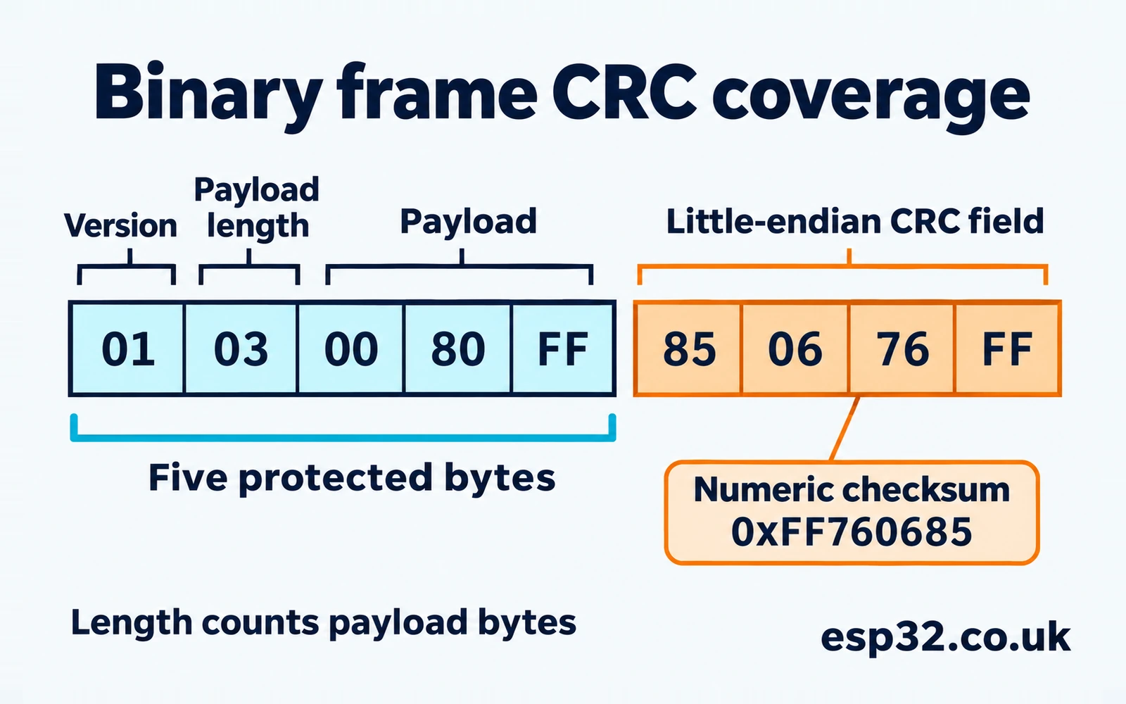
Confirm the bytes with an independent calculator
The example below uses Python’s zlib wrapper on a computer. The first check confirms that the profile is the intended one. The second prints the complete frame as bytes in transmission order. Compare that byte sequence with the data you pass to the MCU.
import zlib

assert zlib.crc32(b"123456789") == 0xCBF43926
data = bytes.fromhex("01 03 00 80 FF")
check = zlib.crc32(data)
assert check == 0xFF760685
frame = data + check.to_bytes(4, "little")
print(frame.hex(" "))
Change the payload byte 80 to 81 and leave the stored CRC unchanged. The new protected bytes calculate to 0xE66D37C4, so the frame check rejects it. Also test a truncated frame and a header declaring too many bytes. That distinguishes checksum mismatches from size and version rejections. For an empty payload, the protected bytes are still 01 00. The full valid frame in that case is 01 00 BE 23 C2 58.
Keep the frame structure separate from the transport. The example assumes the caller already has the bytes of one complete candidate frame. A UART receive callback or DMA event can end halfway through a frame or deliver several frames at once. Add a framing policy and a bounded receive buffer before calling the validator. A marker and a length field, or a delimiter with an escaping rule, can give a receiver a defined point to recover after corruption. STM32 UART and DMA guide
Serialize structured values before calculating the CRC
For an example with a numeric payload, suppose version 1 carries a 16-bit reading of 0x1234 and the payload format stores that field little-endian. The two payload bytes are 34 12. Including the version and payload length, the protected bytes are 01 02 34 12 and their ISO-HDLC CRC is 0xD2EFEEA8. The frame ends with A8 EE EF D2 under this article’s checksum serialization rule.
If the payload definition stores the reading big-endian, the protected bytes become 01 02 12 34 and the checksum becomes 0xC33CE871. Both are coherent messages under different payload definitions. The receiver needs to agree on how the reading is represented as well as on how the checksum field is represented. This is independent of the hardware word packing used to calculate the checksum from either stream.
Avoid feeding the raw memory of a C structure as the protocol definition. The compiler can insert padding between fields, and the in-memory order of a multi-byte field follows the target. Serialize the fields to explicit byte offsets, compute the checksum over the produced bytes and transmit that buffer. On reception, verify the exact bytes first and then decode the fields. This keeps compiler layout changes out of the checksum contract.
When bringing up a sender, save a short hex dump from immediately before the transport write. Compare it with a dump taken before the receiver validates or rewrites any fields. If the protected bytes differ, fix serialization or receive framing first. If they match, compare the numeric CRC and its stored representation separately.
Keep the message stable while checking it
If DMA receives into a circular buffer, the bytes can change while the CPU is reading them. Move a complete frame into a buffer owned by the validator or arrange a handoff that prevents the DMA writer from reusing it until the calculation finishes. A volatile pointer does not make a frame snapshot consistent. The checksum needs the same complete bytes that the receiver will parse and use. STM32 DMA memory-to-memory guide
CRC protection at one layer is separate from a bus’s own error detection. An SPI peripheral’s optional CRC logic belongs to its SPI transfer format, and CAN performs its own frame checks. Use the application checksum when the protected object has a lifetime beyond an individual bus frame, such as a stored payload or a message that crosses multiple transport segments. Keep each checksum definition and its coverage in the protocol documentation. STM32 SPI and HAL guide
Plan buffer size, continuation and verification
The staging array is fixed at 32 bytes. For a 1,027-byte message, 1,024 bytes form 256 words, so the example makes 32 hardware accumulation calls and processes the remaining three bytes in software. The total work also includes byte loads, packing, optional reflection and HAL call overhead. A word-native message can be fed with fewer copies if its representation already matches the stream contract. Compare complete code paths on the target before drawing a speed conclusion from the presence of a hardware peripheral.
For repeatable timing, use a fixed-size buffer, run enough checksums to see the cost, and ensure the result is consumed so the compiler preserves the work. Measure with the same compiler options and clock for both implementations. Separate the cost of transferring or receiving the data from the cost of checksumming it. With small packets, function calls and packing can account for much of the elapsed time.
When verifying a file or a region of Flash, agree on the actual byte sequence. A linker image can have holes, section padding and a separate metadata field for the checksum. A binary file can include fill bytes that are absent from a selected set of ELF sections. Define a start address, a length and the treatment of any stored checksum field. Use the same rule in the desktop generator and firmware verifier. STM32 boot modes and firmware images
If you calculate across a message in pieces, keep a running state in one representation until the end. The value from zlib’s incremental API is suitable for passing back to that API. The raw STM32 register state has a different representation when you are adapting the reflected profile. Record which form you save in a test log. Finishing each fragment with a final XOR and starting the next with a hardware reset calculates separate fragment checksums.
Agree on the exact range for a Flash checksum
For a checksum generated at build time and checked from Flash later, write down the byte range and verify it on both sides. An inclusive final address and an exclusive end address differ by one byte. A format defined as start plus length avoids that ambiguity as long as both tools use the same values. If the checksum is stored at the end of the image, specify whether those four bytes are outside the protected length or are handled by another explicit rule.
Padding needs the same treatment. A blank Flash location typically reads as all ones, while a packaging tool may fill an address gap with zero bytes. The checksum over a raw file and the checksum over a readback can differ if the tools represent gaps differently. Verify a small image that includes a gap and compare the bytes at that address before debugging the polynomial. Repeat the test after an update if the linker layout changes.
Use a known file and save the reference CRC together with its profile and byte length. If the board disagrees, compare a small prefix that ends on a word boundary, then move the boundary by one byte. A match for the prefix and a failure on the full region can point to a different length, fill byte or metadata rule. Keeping the range and vector in the same test makes it easier to reproduce the result after changes to the build.
Troubleshoot STM32 CRC32 mismatches
| Symptom | First check | Likely area |
|---|---|---|
| Lab call returns false | Handle, RCC CRC clock, profile and pointers | Input or project initialisation |
| Four-byte test fails | Compare the written word with 0x31323334 | Word packing or reset state |
| First call matches, later calls vary | Check Calculate versus Accumulate and peripheral ownership | Unintended continuation or interleaving |
| MPEG-2 matches but zlib differs | Per-byte reflection, final reflection and XOR | Profile conversion |
| Multiples of four match but other lengths fail | Inspect the exact final bytes and total length | Padding or a missing software tail |
| Check string fails in the terminal but works in C | Inspect newline, zero terminator and text encoding | Different input bytes |
| Numeric result matches but packet fails | Check protected length and stored byte order | Frame format |
| Reading CRC_DR differs from the returned value | Check the tail and final transformation | Raw prefix state compared with finished checksum |
Start with the shortest useful vector. Check an empty input, then a complete four-byte word, then the same word plus one byte. If the empty input fails, check the setup and output transformation. If four bytes fail, inspect the numerical word passed to HAL. If only the fifth byte breaks agreement, check the tail. This sequence narrows the problem without changing several parameters at once.
If another task or interrupt uses the CRC peripheral, run the same checks with the concurrent access removed from the test project. A correct test vector can fail intermittently if another context resets the hardware while a message is being accumulated. Once each user works in isolation, add a shared ownership rule and test interleaved requests at the application level.
Use the mismatch itself as a clue
For ISO-HDLC, ASCII 123456789 with a single zero byte appended gives 0x00C49E49. With a line feed appended it gives 0xE0117757. Those values differ from both the nine-byte check value and the result of padding with three zeros. If one of them appears in a debugger, check the length passed by the C caller or the line ending used by the desktop test. Hexadecimal output with eight digits also makes the leading zeros visible.
Keep a test set with at least one length in each residue class modulo four and a buffer starting at an odd address. Include bytes with the high bit set as well as ASCII digits. A cast-based packer can work by accident on aligned text and then fail when a payload starts inside a receive buffer. The supplied native tests cover all four offsets, both profiles and lengths on both sides of the 32-byte staging boundary.
Questions about the STM32F103 CRC peripheral
Why does CRC_IDR accept a byte?
CRC_IDR is an independent eight-bit register. It can hold application data and is unaffected by the CRC calculator’s RESET operation. The byte does not pass through the checksum recurrence. The CRC data path on this F103 target consumes whole words through CRC_DR.
Can I reset the hardware to a different initial value?
The F103 CRC reset loads all ones. For a protocol with a different seed, implement the required recurrence in software or use a peripheral that can express those settings. Check the exact STM32 part when porting the code.
Should the checksum in a frame always be little-endian?
Choose the order defined by the protocol. This example uses little-endian serialization for its four-byte field. The receive code assembles that field explicitly, so the comparison does not depend on the CPU’s native order or on alignment.
What if my input is an array of 32-bit numbers?
Define how those numbers are meant to enter the checksum. If the protocol specifies the numeric words as inputs, feeding them directly may be appropriate. If it specifies a stream of bytes, serialize the numbers in the agreed order before calculating the checksum. Confirm the convention with a vector containing unequal bytes.
Datasheets & External Resources
| Source | What to check |
|---|---|
| ST DS5319 STM32F103x8/xB datasheet | CRC peripheral availability on the device |
| ST RM0008 reference manual | CRC data, independent and control registers |
| ST AN4187 using the CRC peripheral | F1 feature limits and CRC migration |
| ST STM32F1 HAL CRC v1.1.10 | Reset, accumulation and word counts |
| Arm CMSIS core intrinsics | RBIT and REV operations |
| CRC RevEng profile catalogue | CRC-32/MPEG-2 and CRC-32/ISO-HDLC parameters and check values |
| zlib checksum documentation | Initialisation and continuation in the public CRC32 API |