
When a UART sends a byte or an ADC finishes a conversion, the CPU can move the data itself. Direct memory access, or DMA, gives the transfer to a hardware controller. That can free the CPU for other work and make a stream easier to service. It also introduces a new set of questions. Which channel owns the request? How many items will it move? When can the application read or reuse the buffer?
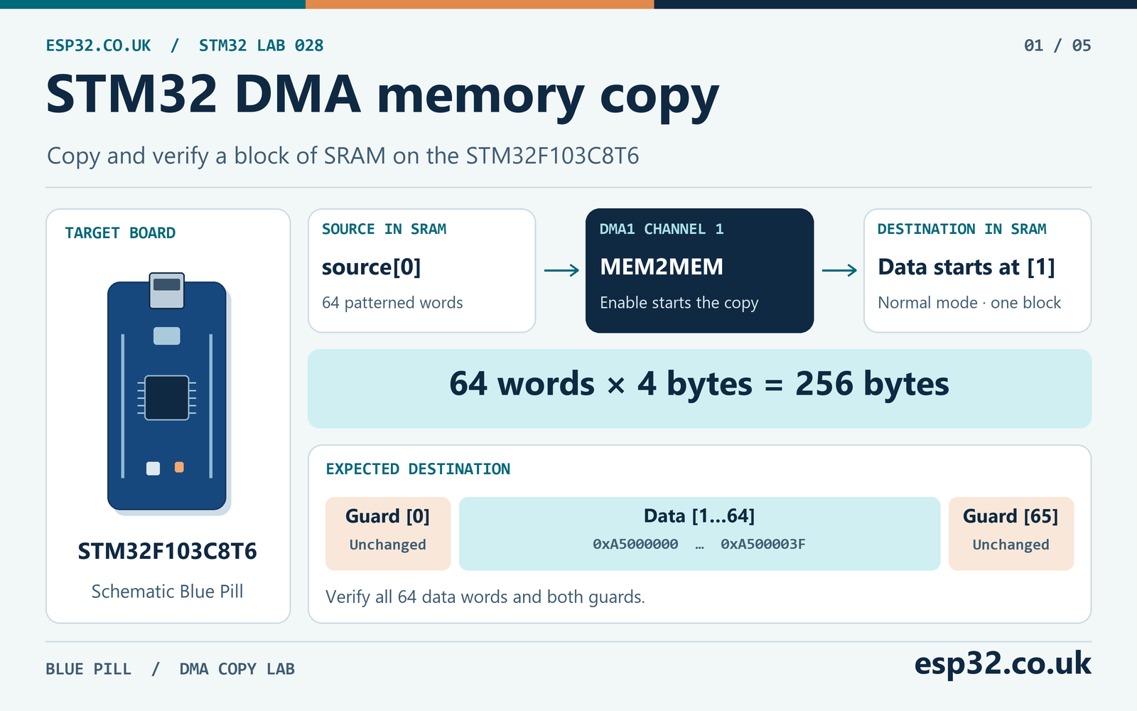
In this esp32PriceAliExpress price.co.uk/ guide, you will answer those questions with a Blue PillPriceAliExpress price memory-to-memory experiment. DMA1 channel 1 copies 64 words between two arrays in SRAM on an STM32F103C8T6PriceAliExpress price. The program verifies the result, checks two guard words and preserves diagnostic information for the debugger. The exercise uses HAL to initialise the channel and explicit register operations to make the transfer sequence visible.
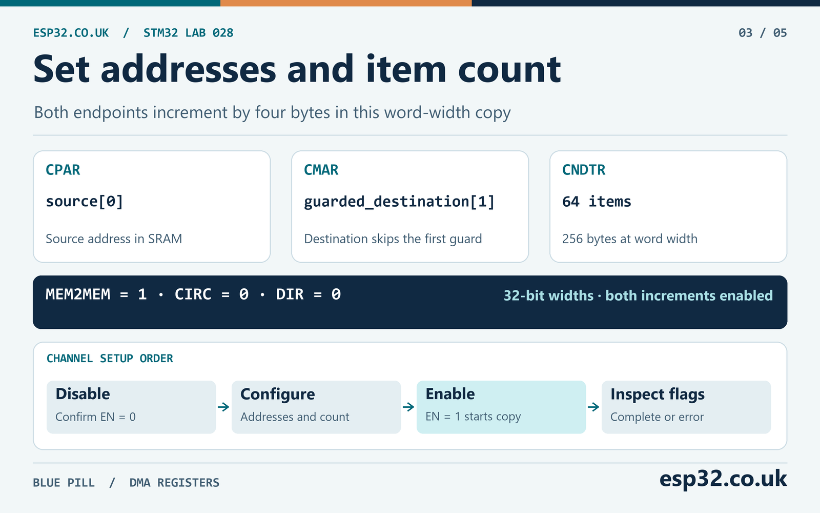
Quick answer. Enable DMA1, configure channel 1 for memory-to-memory mode, select word width and increment both address sides. While the channel is disabled, put the source in CPAR, the destination in CMAR and the item count of 64 in CNDTR. Enable the channel, wait for completion or error, then verify that 256 bytes were copied. The lab needs the board and an SWD programmer.
What DMA does on the STM32F103C8
DMA is a separate bus master. Firmware configures a channel with a source address, destination address, transfer width, item count and request mode. Once enabled, the controller performs the bus accesses. A peripheral transfer usually waits for a request from a device such as ADC1 or USART1. The memory-to-memory lab uses software-started transfers and therefore needs no peripheral trigger. ST STM32F103x8/xB datasheet
The STM32F103C8 has one DMA controller with seven channels. Other F1 variants can add another controller, and other STM32 families can use streams, request multiplexers or linked descriptors. Use the manual for the exact device in your project. An example for an F4 stream cannot tell you which F103 channel owns an ADC request.
| Transfer direction | Typical source | Typical destination | Who supplies the request |
|---|---|---|---|
| Peripheral to memory | ADC or USART data register | Array in SRAM | Peripheral |
| Memory to peripheral | Transmit array in SRAM | USART or SPI data register | Peripheral |
| Memory to memory | Source array in SRAM | Separate destination array | Channel enable in memory-to-memory mode |
In a receive transfer, the peripheral address generally stays fixed because new samples arrive at the same register. The memory address increments to save each item in a new slot. A RAM copy usually increments both addresses. Deliberately disabling one increment can be useful, for example when repeatedly sending a single value. Doing that accidentally gives a buffer full of repeated values or a transfer that repeatedly overwrites its first slot.
The CPU can execute while DMA is active, but both may need the same bus target. DMA channel priority helps the controller select between requests. Bus arbitration also determines when a bus master can access a target. A high channel priority cannot remove all bus contention or turn a slow peripheral into a faster one. Measure behaviour with the other activity your application will actually run. ST AN2548, Introduction to DMA controller for STM32 MCUs
Check the fixed DMA1 request map before assigning channels
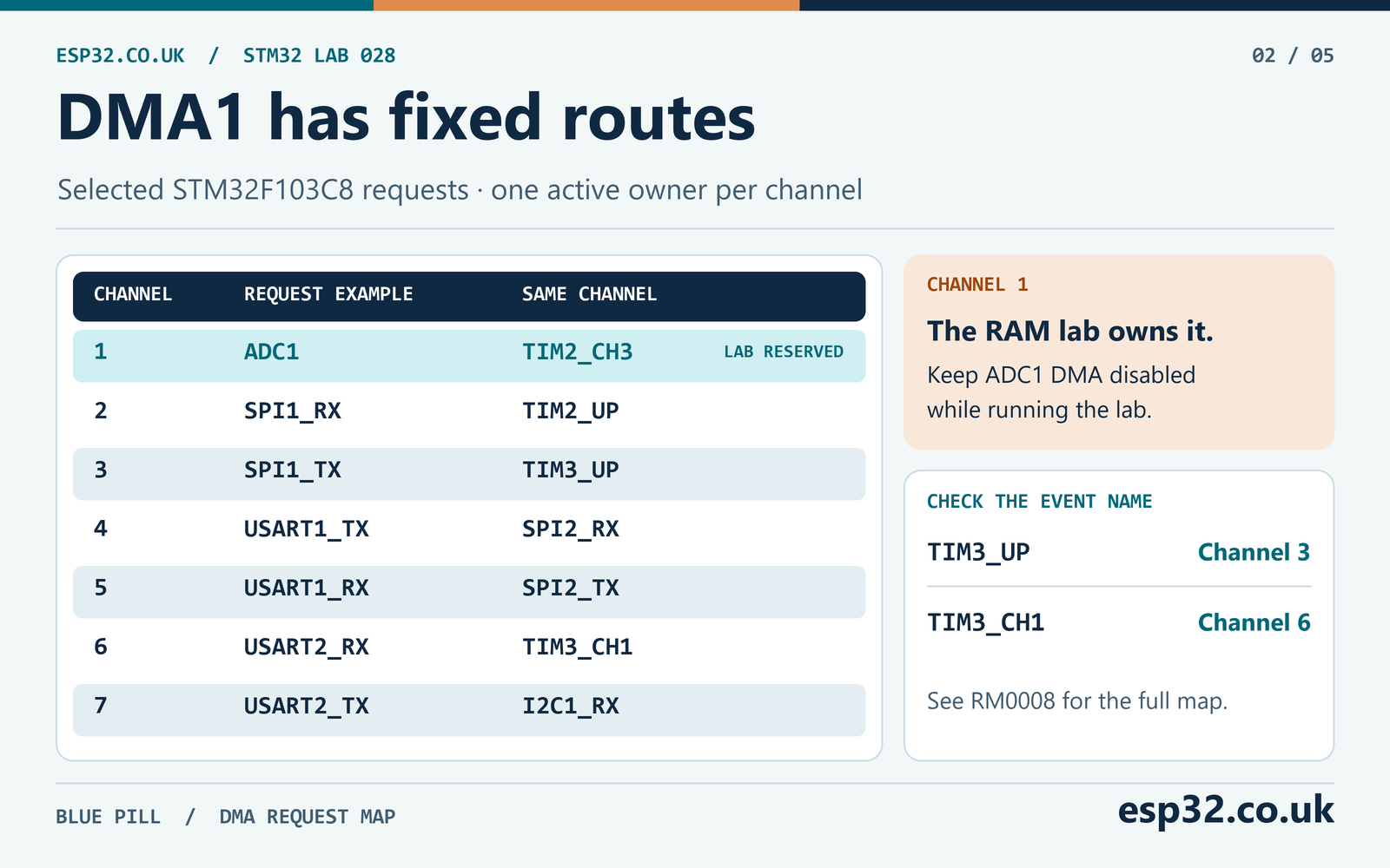
On this F103, several hardware request sources can feed the same DMA channel. Their mapping is fixed. Software enables the desired request at its peripheral and configures the associated channel. If two devices drive the same channel concurrently, the DMA channel cannot infer which address or buffer belongs to each request. Plan one active owner per channel and one configuration for that owner. ST RM0008, DMA request mapping
| DMA1 channel | Selected STM32F103C8 requests | Example design implication |
|---|---|---|
| 1 | ADC1, TIM2_CH3, TIM4_CH1 | This lab reserves channel 1, so keep ADC1 DMA disabled |
| 2 | SPI1_RX, USART3_TX, TIM2_UP | SPI1 receive conflicts with DMA from TIM2 update on this channel |
| 3 | SPI1_TX, USART3_RX, TIM3_UP | SPI1 transmit and TIM3 update need separate scheduling |
| 4 | USART1_TX, SPI2_RX, I2C2_TX | Check competing devices before choosing USART1 DMA |
| 5 | USART1_RX, SPI2_TX, I2C2_RX | USART1 receive needs its own buffer and ownership |
| 6 | USART2_RX, I2C1_TX, TIM3_CH1 | Verify timer and I²C transmit usage |
| 7 | USART2_TX, I2C1_RX, TIM4_UP | Check the receive channel as well as transmit |
The table gives selected examples. Check RM0008 for the complete mapping before enabling an additional request. A timer update request and a timer channel compare request are distinct sources. For instance, TIM3_UP is on channel 3 while TIM3_CH1 is on channel 6. Selecting a pin for a timer channel in CubeMX does not make every timer event use that same DMA route.
Channel priority applies when DMA requests compete. The F1 controller offers four software priority levels. When channels have equal programmed priority, the lower-numbered channel has priority within that controller. This differs from NVIC priority, which governs servicing CPU interrupts. Changing NVIC priority does not move an ADC request to another DMA channel or change the DMA controller’s request mapping.
Use this map before combining series examples. The ADC1 circular sample buffer from the ADC tutorial already uses channel 1. If you want that acquisition running alongside a RAM copy, move the memory-to-memory lab to an otherwise unused channel and update every associated register, flag and configuration. The memory copy’s software start can use another available channel, while ADC1 keeps its fixed hardware mapping. STM32 ADC, calibration and DMA tutorial
Calculate the item count, width and alignment
The transfer count is the number of DMA items. It is easy to mix it up with a byte count because copying a byte array makes the two numbers equal. In this lab both endpoint widths are 32 bits, so each item is four bytes. A length of 64 is 256 bytes. Passing the array’s byte size as the item count would request 256 words and write far past the allocated destination.
| Buffer declaration | Width at both endpoints | CNDTR for the whole array | Bytes copied |
|---|---|---|---|
| uint8_t data[64] | Byte | 64 | 64 |
| uint16_t data[64] | Halfword | 64 | 128 |
| uint32_t data[64] | Word | 64 | 256 |
The 16-bit CNDTR field can represent at most 65,535 items. A zero count moves no items. The F1 HAL’s valid length check follows the nonzero range through 65,535. A count limit does not mean the target has enough SRAM for a block that large. The STM32F103C8 has 20 KB of SRAM, and both buffers share it with the stack, globals and any heap. Measure actual free capacity with the linker map. ST HAL DMA header v1.1.10
Match addresses to the selected width. Ordinary word arrays give word-aligned addresses in the target toolchain, and adding one word for a guard preserves that alignment. A byte array plus an arbitrary offset does not guarantee a valid word address. Inspect both pointers and any offset or packed structure that created them. Choose equal widths for an ordinary copy. Different widths have device-specific transfer behaviour and should be used only with a clear reason and register documentation.
In the STM32F1 register layout, CPAR and CMAR name the two address sides. In this memory-to-memory configuration the channel reads from CPAR and writes to CMAR. Both point into SRAM, even though CPAR carries the peripheral-side name. That is why the HAL options named peripheral width and peripheral increment still matter in this lab. The tagged HAL source uses this same source and destination order for its memory-to-memory start path. ST HAL DMA implementation v1.1.10
Use disjoint buffers for the exercise. The lab does not implement the overlap rules of memmove(). If a source and destination overlap, later reads could see values that earlier writes have already changed. Start with separate arrays and verify their placement in the debugger before adapting the approach to a more complex data layout.
Prepare the Blue Pill project
Create a C project for STM32F103C8Tx with STM32CubeF1. Keep Serial Wire debugging enabled and use a normal working clock setup with an advancing HAL millisecond tick. No particular CPU frequency is required for the copy. You can use the board’s working internal oscillator setup. The timeout measures HAL ticks rather than a count of instruction cycles.
The lab owns DMA1 channel 1 and expects no other use of it. Leave it unassigned in CubeMX for this example. The module enables DMA1’s clock and calls HAL_DMA_Init() itself. Enable HAL_DMA_MODULE_ENABLED in the project’s HAL configuration and ensure stm32f1xx_hal_dma.c is built. In a minimal generated project, CubeMX may omit the DMA driver from the build. Use the driver from the same CubeF1 package as the other HAL files.
| Setup item | Lab value | Reason |
|---|---|---|
| MCU | STM32F103C8Tx | Matches the Blue Pill and F1 channel map |
| Channel | DMA1 channel 1 | Owned exclusively by this lab |
| Direction | Memory to memory | Channel enable starts the copy |
| Mode | Normal | One finite block |
| Both widths | Word | Matches uint32_t arrays |
| Both increments | Enabled | Advances through both arrays |
| Channel priority | Low | Sufficient for the isolated lab |
| DMA interrupt | Unused | Main loop observes flags directly |
| HAL tick | Running in foreground | Bounds the polling wait |
The source is filled with consecutive values starting at 0xA5000000. The destination data slots begin at zero, with one sentinel word on each side. The data starts at destination index 1, so the transfer should finish at index 64, immediately before the final sentinel. A changing pattern lets you detect a repeated source value, wrong stride or reversed direction more easily than copying an array of identical words.
Keep the test independent of other transfers until it passes. Use the debugger to confirm the chip and memory map if the board behaves differently from a genuine F103. For basic SWD and board bring-up, see the earlier Blue Pill pinout guide. STM32F103C8T6 Blue Pill pinout
Build the guarded RAM-to-RAM copy
Copy dma_lab.h into Core/Inc and dma_lab.c into Core/Src. The function runs in the foreground after normal startup. It returns a result enum and exposes the observed status flags, the remaining item count and the first bad array index. A guard or count failure can leave the index at UINT32_MAX, because that failure does not identify a mismatched payload item.
#ifndef DMA_LAB_H
#define DMA_LAB_H

#include <stdint.h>

enum { DMA_LAB_WORDS = 64 };

typedef enum {
    DMA_LAB_NOT_RUN,
    DMA_LAB_OK,
    DMA_LAB_CHANNEL_BUSY,
    DMA_LAB_INIT_ERROR,
    DMA_LAB_TRANSFER_ERROR,
    DMA_LAB_TIMEOUT,
    DMA_LAB_STOP_FAILED,
    DMA_LAB_VERIFY_ERROR
} DmaLabResult;

extern volatile uint32_t dma_lab_flags;
extern volatile uint32_t dma_lab_remaining;
extern volatile uint32_t dma_lab_first_bad_index;

DmaLabResult DmaLab_Run(void);

#endif
The code verifies ownership at entry by checking that the channel is disabled. The wider project must still reserve channel 1 for the lab. A disabled channel may belong to an idle peripheral driver that will use it later. Clear the old channel configuration while it is stopped, configure the F1 HAL handle and set up the block explicitly. The HAL handle is local because no interrupt or later callback refers to it.
#include "dma_lab.h"
#include "stm32f1xx_hal.h"

#define FIRST_WORD UINT32_C(0xA5000000)
#define BEFORE_GUARD UINT32_C(0xA55AA55A)
#define AFTER_GUARD UINT32_C(0x5AA55AA5)
#define WAIT_MS 25U
#define CHANNEL1_FLAGS (DMA_ISR_HTIF1 | DMA_ISR_TCIF1 | DMA_ISR_TEIF1)
#define CHANNEL1_CLEAR (DMA_IFCR_CHTIF1 | DMA_IFCR_CTCIF1 | DMA_IFCR_CTEIF1)

static volatile uint32_t source[DMA_LAB_WORDS];
static volatile uint32_t guarded_destination[DMA_LAB_WORDS + 2U];

volatile uint32_t dma_lab_flags;
volatile uint32_t dma_lab_remaining;
volatile uint32_t dma_lab_first_bad_index;

DmaLabResult DmaLab_Run(void)
{
    __HAL_RCC_DMA1_CLK_ENABLE();
    if ((DMA1_Channel1->CCR & DMA_CCR_EN) != 0U) {
        return DMA_LAB_CHANNEL_BUSY;
    }

    /* This foreground-only lab owns DMA1 channel 1 and both arrays. */
    DMA1_Channel1->CCR = 0U;
    DMA_HandleTypeDef dma = {0};
    dma.Instance = DMA1_Channel1;
    dma.Init.Direction = DMA_MEMORY_TO_MEMORY;
    dma.Init.PeriphInc = DMA_PINC_ENABLE;
    dma.Init.MemInc = DMA_MINC_ENABLE;
    dma.Init.PeriphDataAlignment = DMA_PDATAALIGN_WORD;
    dma.Init.MemDataAlignment = DMA_MDATAALIGN_WORD;
    dma.Init.Mode = DMA_NORMAL;
    dma.Init.Priority = DMA_PRIORITY_LOW;
    if (HAL_DMA_Init(&dma) != HAL_OK) {
        return DMA_LAB_INIT_ERROR;
    }

    dma_lab_flags = 0U;
    dma_lab_remaining = DMA_LAB_WORDS;
    dma_lab_first_bad_index = UINT32_MAX;
    guarded_destination[0] = BEFORE_GUARD;
    guarded_destination[DMA_LAB_WORDS + 1U] = AFTER_GUARD;
    for (uint32_t i = 0; i < DMA_LAB_WORDS; ++i) {
        source[i] = FIRST_WORD + i;
        guarded_destination[i + 1U] = 0U;
    }

    DMA1->IFCR = CHANNEL1_CLEAR;
    DMA1_Channel1->CPAR = (uint32_t)(uintptr_t)&source[0];
    DMA1_Channel1->CMAR = (uint32_t)(uintptr_t)&guarded_destination[1];
    DMA1_Channel1->CNDTR = DMA_LAB_WORDS;

    uint32_t started = HAL_GetTick();
    __DMB();
    SET_BIT(DMA1_Channel1->CCR, DMA_CCR_EN);

    DmaLabResult result;
    uint32_t flags;
    for (;;) {
        flags = DMA1->ISR & CHANNEL1_FLAGS;
        if ((flags & DMA_ISR_TEIF1) != 0U) {
            result = DMA_LAB_TRANSFER_ERROR;
            break;
        }
        if ((flags & DMA_ISR_TCIF1) != 0U) {
            result = DMA_LAB_OK;
            break;
        }
        if ((uint32_t)(HAL_GetTick() - started) >= WAIT_MS) {
            result = DMA_LAB_TIMEOUT;
            break;
        }
    }

    dma_lab_flags = flags;
    CLEAR_BIT(DMA1_Channel1->CCR, DMA_CCR_EN);
    if ((DMA1_Channel1->CCR & DMA_CCR_EN) != 0U) {
        return DMA_LAB_STOP_FAILED;
    }
    dma_lab_remaining = DMA1_Channel1->CNDTR;
    DMA1->IFCR = CHANNEL1_CLEAR;
    __DMB();
    if (result != DMA_LAB_OK) {
        return result;
    }

    if (dma_lab_remaining != 0U || guarded_destination[0] != BEFORE_GUARD ||
        guarded_destination[DMA_LAB_WORDS + 1U] != AFTER_GUARD) {
        return DMA_LAB_VERIFY_ERROR;
    }
    for (uint32_t i = 0; i < DMA_LAB_WORDS; ++i) {
        if (source[i] != FIRST_WORD + i ||
            guarded_destination[i + 1U] != FIRST_WORD + i) {
            dma_lab_first_bad_index = i;
            return DMA_LAB_VERIFY_ERROR;
        }
    }
    return DMA_LAB_OK;
}
In main.c, place the include and variable declaration in their generated user-code sections. Run the test once after HAL_Init() and normal clock setup, before the main loop. These lines belong in the marked locations of the generated project.
/* USER CODE BEGIN Includes */
#include "dma_lab.h"
/* USER CODE END Includes */

/* USER CODE BEGIN PV */
volatile DmaLabResult dma_lab_result;
/* USER CODE END PV */

/* USER CODE BEGIN 2 */
dma_lab_result = DmaLab_Run();
/* USER CODE END 2 */
Run the program without stopping in the middle of the transfer. Put a breakpoint on the first instruction after the result assignment or inspect live variables after the test returns. A passing run reports DMA_LAB_OK, dma_lab_remaining == 0 and dma_lab_first_bad_index == UINT32_MAX. The data words should range from 0xA5000000 through 0xA500003F, with the first and last guards unchanged.
The module and ST’s DMA driver compiled as Cortex-M3 objects against the checked HAL and CMSIS headers. The program still needs to be integrated into a generated project, linked and flashed for the hardware measurements in this guide. The package’s validation report records the build scope.
Understand completion, timeout and error handling
The hardware flags distinguish half transfer, transfer complete and transfer error. This foreground example polls the status register, checks an error before accepting completion and stops waiting at 25 HAL milliseconds. Because there is no DMA interrupt handler clearing the same flags, the polling loop owns their acknowledgement. Avoid combining a polling wait with an interrupt handler that consumes the flags you are waiting to see.
| Lab outcome | First evidence | What to check |
|---|---|---|
| OK | Completion, zero remaining and matching data | Expected result |
| Channel busy | EN already set at entry | Who owns channel 1 |
| Initialisation error | HAL initialisation failed | Project HAL setup and configuration |
| Transfer error | TEIF1 observed | Address, width and bus access |
| Timeout | Completion and error absent when the wait expired | Tick, mode, channel clock and request source |
| Stop failed | EN still set after requesting disable | Treat the buffers as still owned by DMA |
| Verify error | Count, guard or data mismatch | Inspect widths, addresses and both increments |
The timeout is a fault limit, not a benchmark for a 256-byte copy. The HAL tick must run. Calling this foreground example from an interrupt that blocks the tick could prevent the wait from expiring. A timeout also does not prove the destination is untouched. A transfer could have written a prefix before the timeout, or could have finished after the last flag sample. The lab checks that the channel is disabled before releasing or inspecting the buffer and returns the failure instead of accepting partial data.
DMA1 uses a write-to-clear register. This example acknowledges the individual half, complete and error flags after disabling the channel. ST’s medium-density device errata describes a case where clearing the channel’s global flag at the same time as a transfer error can interfere with the normal error handling. Check the errata for the device revision when modifying the code or using another driver path. ST ES096, DMA limitation
The initialisation and transfer styles are deliberately separate. A simpler application may use HAL_DMA_Start() and HAL_DMA_PollForTransfer() on a dedicated normal-mode handle. Read the version of the driver that will run on your board before writing recovery logic. In the reviewed F1 version, the polling timeout updates HAL’s software state without explicitly disabling the channel in that timeout branch. Check hardware ownership before returning the buffer to application code. This tutorial uses the explicit stop and readback sequence so the ownership decision is visible. ST HAL DMA polling and state handling
Read the configuration in the debugger
Examine the channel at two deliberate points. Before enabling it, check the start addresses, count and control fields. After the function returns, inspect its software snapshots alongside the remaining count and data. A debugger view of the live status register after cleanup can show no completion flag even when the copy passed. The lab has already acknowledged the flags and saved the observed bits in dma_lab_flags.
| Field | Expected before start | Expected after a successful copy |
|---|---|---|
| CCR.EN | 0 until the start write | 0 after explicit disable |
| CCR.MEM2MEM and CCR.CIRC | 1 and 0 | Configuration retained |
| CPAR and CMAR | Source and first destination data slot | Base addresses retained |
| CNDTR | 64 items | 0 items |
| DMA1.ISR channel 1 completion bit | Clear after initial acknowledgement | Clear after final acknowledgement |
| Saved completion bit | Initial snapshot is zero | Set in the saved status |
Use the debugger’s normal 32-bit register view if manually inspecting these registers. The F1 errata document also clarifies the access width of DMA control registers. A transfer with byte-sized payloads still uses aligned word accesses to program the controller’s registers.
Try a second invocation after the first run has returned and while channel 1 is still reserved. The lab refills the arrays and clears old flags before re-enabling the channel. This checks the same start and cleanup sequence twice. If the second invocation reports that the channel is busy, diagnose ownership or stop behaviour before inspecting payload bytes. An unexpected guard value should be treated as a failed test even if the 64 expected data values are correct.
Move from a one-shot transfer to continuous data
The RAM lab uses normal mode. A peripheral stream can use circular mode, where the controller reloads the transfer count and returns to the start of its buffer. On this controller, keep the software-started memory-to-memory exercise in normal mode. Circular mode is useful for repeated peripheral requests such as regular ADC conversions, where every conversion gives the DMA a reason to move one item.
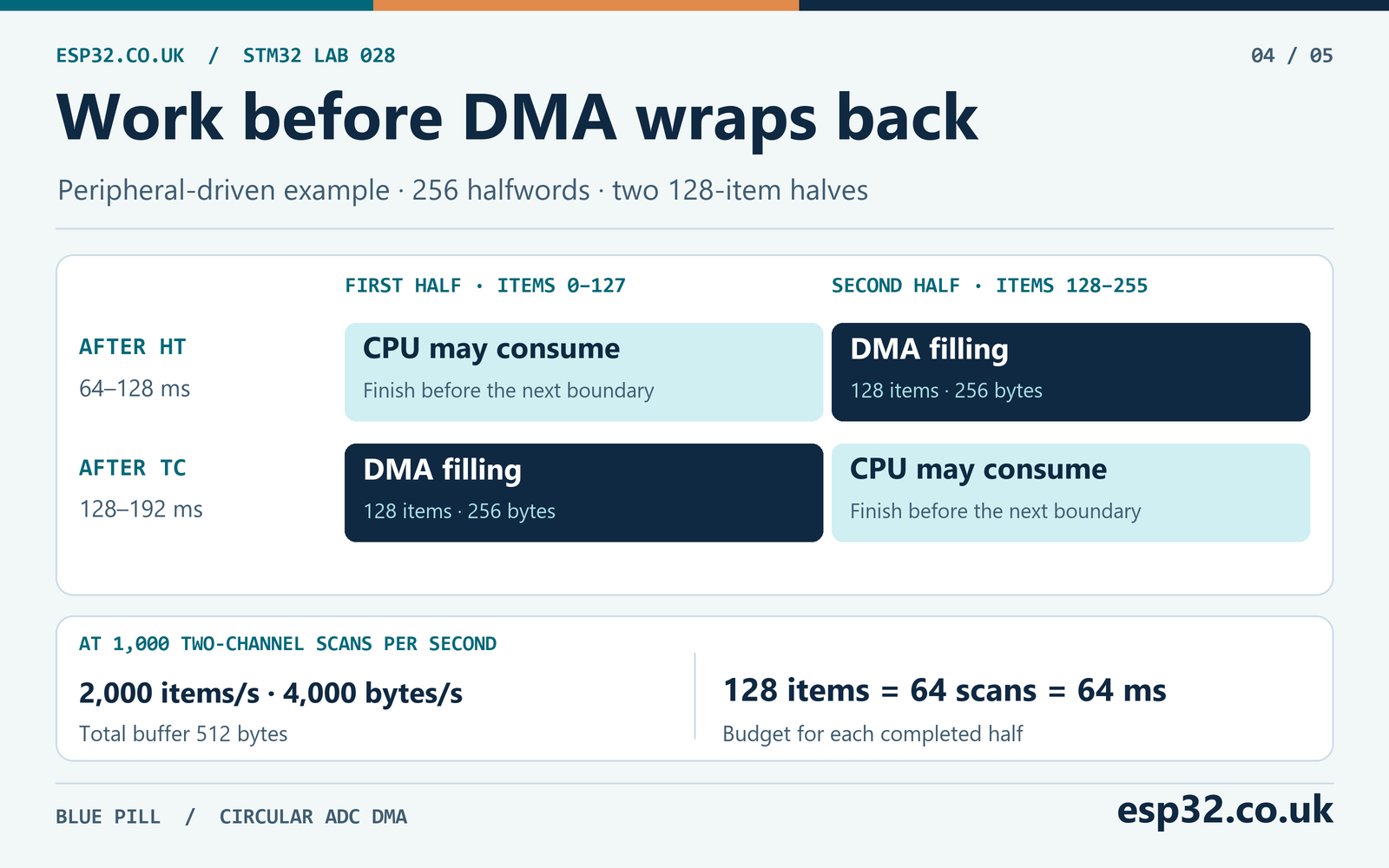
With an even circular buffer, a half-transfer notification can hand the first half to the application while DMA fills the second. The complete notification can hand over the second while DMA returns to the first. Each handoff starts a deadline. When DMA comes back to that region it can overwrite old data, so the consumer must finish reading or copying it first.
For example, suppose ADC1 scans two channels 1,000 times per second and each conversion uses a halfword in memory. The transfer rate is 2,000 items per second, or 4,000 bytes per second. A buffer of 256 halfwords holds 128 scans. Each half holds 128 conversions, or 64 complete scans. The application gets about 64 ms between half-buffer boundaries when the scan rate is stable. That budget includes wake-up latency, processing and any time the foreground spends on other work.
| Circular ADC example | Calculation | Result |
|---|---|---|
| Conversion rate | 2 channels × 1,000 scans/s | 2,000 items/s |
| Payload rate | 2,000 items/s × 2 bytes | 4,000 bytes/s |
| Total RAM | 256 halfwords × 2 bytes | 512 bytes |
| Scans per half | 128 items ÷ 2 channels | 64 scans |
| Time per half | 64 scans ÷ 1,000 scans/s | 64 ms |
Choose a buffer size that leaves whole scan frames in each half. For three channels, for instance, a half-buffer item count should be a multiple of three if you want each handoff to start on a frame boundary. Otherwise the consumer must carry a partially processed frame across the boundary. Account for channel order when interpreting values. DMA stores a sequence of samples, and the application decides what each slot represents.
A single Boolean ready flag can hide lost work if several notifications occur before the consumer runs. A sequence counter or small queue can make missed handoffs observable. Even a queue cannot save a half-buffer that DMA has already overwritten. Define a policy for late consumption, such as dropping the affected block and reporting an overrun. Keep processing out of the ISR where practical and verify how long the consumer takes under its worst expected load.
Use peripheral DMA without losing the transaction boundary
For USART transmit, the DMA request rate follows the UART. At 115,200 baud with 8N1 framing, each payload byte takes ten bit periods including start and stop. The ideal continuous payload rate is 11,520 bytes per second. A 128-byte block then takes about 11.11 ms on the wire, excluding idle gaps. DMA reduces the need for CPU service per byte, while the configured baud rate still sets wire time.
A DMA completion flag can mean the final byte was written to a peripheral register. That is distinct from the UART’s transmission-complete condition, which matters when switching an RS-485 driver from transmit to receive or shutting down a clock. Prefer the peripheral HAL completion path where it already manages that distinction. When using registers directly, check the peripheral’s own final condition and error flags. STM32 UART with HAL, interrupts and DMA
SPI has a related issue with chip select. Keep CS asserted until the intended transaction is complete on the bus. Verify transmit and receive lengths and the selected SPI frame width, since a full-duplex transaction clocks both sides together. Reading from a sensor can require transmitting dummy data to create clock edges. The SPI HAL and the device’s data sheet define how to complete and delimit the operation. STM32 SPI tutorial with HAL and DMA
Interrupt-driven DMA can free the foreground while the transfer runs. With a generated HAL peripheral project, check that the DMA handle is linked to the peripheral, its vector is enabled and the vector dispatches the matching HAL handler. The completion callback should publish a small notification or advance a state machine. Give transmit buffers a lifetime that extends through completion, and read receive data only when the relevant region has been handed over.
Start and stop the producer with the DMA channel
A peripheral receive path needs storage ready when the first sample or byte arrives. In a timer-triggered ADC design, configure the destination and count, arm the DMA and ADC using the matching driver procedure, then start the timer trigger. If the timer is already running, a conversion can arrive while the destination is still being configured. The RAM copy begins on channel enable, so it has no separate producer to start.
Stopping is also an ownership transition. For a controlled pause of a continuous ADC stream, stop future triggers and deal with any conversion or transfer already in flight according to the ADC and DMA driver. Then disable the peripheral’s DMA request and complete the driver stop procedure before reusing memory. A UART receive stream may still have an external transmitter sending bytes, so pausing the local DMA alone cannot preserve that incoming data. A protocol-level pause or a deliberate loss policy can be part of the design.
Treat restart as a new transfer. Re-establish the starting addresses and count, clear the relevant stale status and reset the application’s buffer position or sequence number. Check that the peripheral and DMA are both ready before enabling the next producer. For a circular receiver, define whether the next frame starts at index zero and how you handle any unread data from the previous run.
When the peripheral HAL owns the DMA handle, use its documented start and stop functions to keep its state consistent. The register writes in the RAM lab are for a channel owned solely by that module. Applying the same writes behind a running ADC, SPI or UART driver can leave the hardware and its software handle describing different transfers.
Measure whether DMA helps your workload
Compare two different outcomes. Transfer latency measures how long it takes from requesting the operation to receiving valid data. CPU availability measures how much work the foreground can do while that operation is in progress. A polling DMA copy can be slower than memcpy() for a small block because the CPU spends time setting up DMA and waiting. Asynchronous DMA can still help when useful work overlaps a longer peripheral transfer.
For a bench comparison, keep the source and destination equally aligned, build both paths at the same optimisation setting and use several block sizes. Time the DMA start through the observed completion and time the CPU copy through its return. Verify each result outside the measured region. Ensure the compiler cannot eliminate the CPU copy by making its destination observable after timing. Measure repeated runs with interrupts and other DMA traffic documented.
A scope or logic analyser can measure a spare GPIO raised immediately before a test and cleared after completion. A configured cycle counter or timer can also work. Use enough time resolution to separate short copies and measure the empty instrumentation path to understand its overhead. Report whether setup time is included, and keep a peripheral test’s wire time distinct from DMA setup and CPU service.
When designing a streaming application, measure throughput and the worst service gap. Average throughput can look fine even if a short interruption causes one missed buffer deadline. An acceptance criterion might require zero overruns during a known stress run while capturing at a stated rate. Preserve the measured clock, buffer size and interrupt load so you can reproduce the result after changing the firmware.
Use the same idea when tuning channel priority. Start with the isolated transfer, then add the competing workload one producer at a time. If an ADC buffer begins missing deadlines only while SPI is active, first check that the requests are on separate channels. Then examine the combined interrupt and bus load. Raising a DMA priority may help one consumer at the expense of another, so repeat the timing checks for both streams after the change.
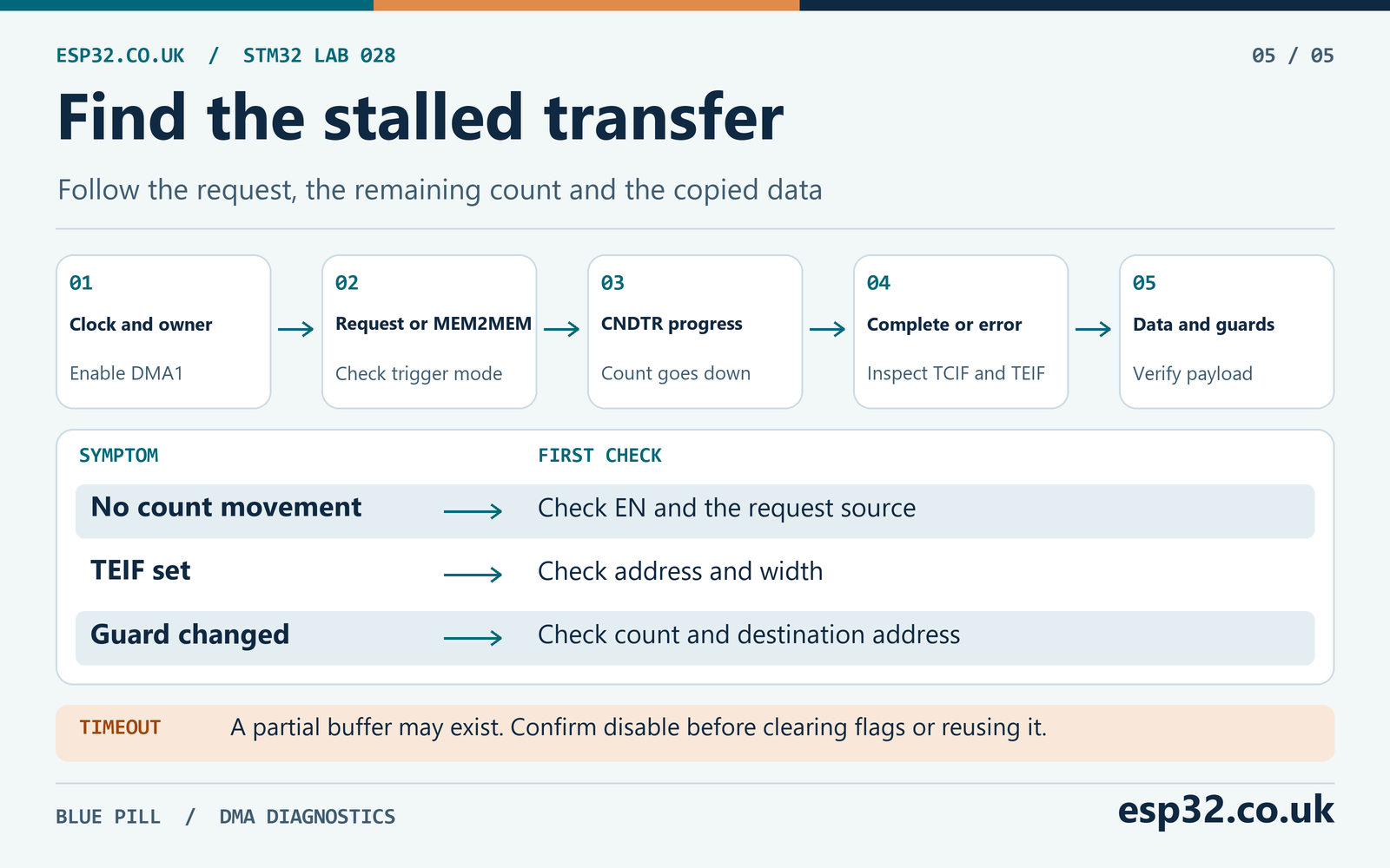
Troubleshoot a transfer from the first failed checkpoint
| Symptom | Inspect first | Likely explanation |
|---|---|---|
| CNDTR does not move | DMA clock, EN and MEM2MEM or request enable | Channel is disabled or no request reaches it |
| Remaining count is smaller but no full completion | Request source and count | The peripheral produced fewer requests than the programmed length |
| Data repeats across the destination | Source increment and width | Source address stays fixed or steps incorrectly |
| Only one slot changes | Destination increment | DMA keeps writing the same address |
| A guard changes | Length, pointer and width | Copy extends beyond the data region |
| TEIF appears | Both addresses and selected widths | Invalid or inaccessible access |
| Data looks correct but callback never runs | NVIC vector and handle link | A polling path or IRQ dispatch is misconfigured |
| A working peripheral fails after adding another | Channel ownership | A second request source uses the same DMA channel |
| Output finishes early on the wire | Peripheral completion condition | DMA has handed over its last item while the peripheral is still busy |
For the RAM lab, break after the copy and inspect CPAR, CMAR and CNDTR. Compare CPAR with the source array and CMAR with the first data slot after the leading guard. If the remaining count is zero but the verification fails, look for a direction, increment or width mistake before changing timeout settings. A transfer-complete flag reports the hardware’s completion of the configured operation. It cannot tell whether that operation matches your intent.
For a peripheral transfer, work from the request source toward the destination. Confirm the peripheral itself is running and producing the events that request DMA. Check that its DMA request bit is set and that the requested event maps to the configured channel. Look at the remaining count after a known number of requests. If the buffer fills and the interrupt is absent, shift your attention to the DMA interrupt enable and NVIC dispatch.
Use a repeatable test pattern. Send a counter or a known short sequence over UART instead of random bytes. For ADC, start with a stable voltage at one channel and deliberately vary only one input at a time. Confirm data width and frame order while it is easy to recognise errors. Once the basic path is correct, increase the rate and test boundary cases such as a full buffer, a dropped request and a restart after a timeout.
Questions about STM32F103 DMA
Can I choose any channel for ADC1 on the Blue Pill?
ADC1 uses DMA1 channel 1 on the STM32F103C8. A software-started memory copy can use another free channel, but hardware request routing follows the fixed device map. Check that the chosen channel is free and that no other peripheral has enabled a request into it.
Is the HAL DMA length measured in bytes?
The generic DMA block length counts items. An item may be one, two or four bytes when the widths match. Peripheral-level HAL APIs can describe length in frames, samples or bytes according to that driver. Check its contract before passing an array size. For the lab, 64 items at word width means 256 bytes.
Do I need a cache clean before starting DMA on an STM32F103?
This Cortex-M3 Blue Pill does not have the data-cache maintenance problem of STM32 parts with a CPU data cache. You still need correct ownership, ordering and visible reads and writes. When porting to a cache-equipped target, check memory accessibility, cache-line alignment and the target’s clean and invalidate rules.
Does DMA save CPU time if I wait in a polling loop?
The controller performs the copy, but the foreground remains occupied by the wait. Polling keeps this first exercise easy to inspect. To overlap useful work with a real data stream, choose an interrupt-driven design with a clear handoff between the DMA engine and its consumer.
Where should I go after the copy works?
Try one peripheral direction at a time. Start with an existing UART or ADC example, identify its fixed channel and show that CNDTR advances only when the expected requests arrive. Then add a timed producer or a continuous buffer with a measured service budget. The earlier timer lab provides the clock and period calculations for generating regular events. STM32 timers and PWM tutorial