
The SH1106 OLED displayPriceAliExpress price module is the controller behind many inexpensive 1.3-inch, 128 × 64 monochrome screens. It is popular for ESP32 weather stations, status displays, battery monitors and simple user interfaces. Its four-pin I²C board can look almost identical to an SSD1306 module, yet code written for the wrong controller may render a shifted image, corrupted columns or a completely blank panel.
In this esp32.co.uk/ hardware guide, we examine the SH1106 board pinout, the differences between I²C and SPI modules, 7-bit addresses 0x3C and 0x3D, 3.3 V ESP32 connection tables, and working examples using Adafruit SH110X and Adafruit GFX. We also explain the subtle but important difference between the SH1106’s 132-column internal RAM and the 128 visible columns on a typical display.
Quick answer: for a verified 3.3 V-compatible four-pin I²C SH1106 module and a classic ESP32-WROOM DevKit, connect 3V3 → VCC, GND → GND, GPIO21 → SDA and GPIO22 → SCL. Scan for 0x3C or 0x3D before initialisation. Use Adafruit_SH1106G rather than an SSD1306-only driver. These are functional pin mappings, not a guarantee about the physical left-to-right order of every cheap breakout.
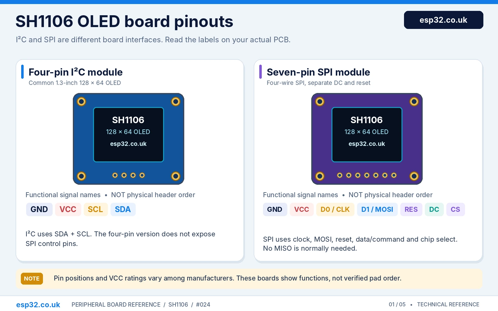
SH1106 specifications and module variants
| Property | What it means in practice |
|---|---|
| Typical screen | 1.3-inch monochrome 128 × 64 pixels, often white or blue OLED |
| Controller RAM | 132 × 64 bits = 1,056 bytes of internal monochrome GDDRAM |
| Typical glass | 128 × 64 visible pixels = 1,024 bytes of ESP32 frame buffer in the Adafruit library |
| Interface support | Controller supports I²C and serial/parallel modes; a breakout may expose I²C or SPI only |
| I²C addresses | Normally 0x3C or 0x3D, determined by a board-level address strap |
| I²C speed | Controller has a 400 kHz fast-mode I²C interface; start testing at 100 kHz |
| Logic supply | Bare SH1106 silicon is low-voltage, not a 5 V-tolerant ESP32 companion |
| Module VCC | Depends on actual carrier regulator, pull-ups and level shifting; verify 3.3 V compatibility |
| SPI control | SCLK, serial-data-in, D/C, CS and usually reset on a seven-pin module |
| Arduino library | Adafruit SH110X with Adafruit GFX; U8g2 is another widely used option |
The underlying SH1106 is not a neat plug-in sensor with eight ordinary GPIOs; its controller is integrated into the OLED panel assembly and the carrier board exposes only the signals its manufacturer chose. Depending on the PCB, an online listing may say “SH1106”, “SH1106G”, “1.3 OLED” or even incorrectly “SSD1306”. Purchase photos and display diagonal alone are insufficient to determine the actual interface or chip.
Four-pin I²C SH1106 breakout pinout
The common 1.3-inch I²C module exposes GND, VCC, SCL and SDA. Some variants print SCK instead of SCL, or place the header in another physical sequence. The correct mapping is the signal function printed by your board, not the contact position copied from an unrelated photograph.
| Board label | Meaning | Classic ESP32-WROOM example |
|---|---|---|
| GND | Ground / power return | GND |
| VCC / VDD | Module supply input; verify rated board voltage | 3V3 on a verified 3.3 V-compatible module |
| SCL / SCK | I²C clock | GPIO22 |
| SDA | I²C bidirectional data | GPIO21 |
If the OLED board has a regulator, its main supply rating may be broader than that of the bare controller. Do not assume the I²C pull-ups are also level shifted. A board operating from 5 V can still pull SDA and SCL to 5 V, which is unsafe for the ESP32. Using an appropriate 3.3 V-compatible module with 3.3 V supply is the preferred direct connection.
Can a four-pin SH1106 be switched to SPI?
Usually not as a simple software setting. A four-pin board exposes I²C power and data but not the separate CS and data/command signals needed by a conventional four-wire SPI configuration. Some display PCBs have documented rear interface-selection pads and alternative unpopulated headers, but these designs vary. Do not bridge or cut a generic solderPriceAliExpress price pad in the hope of enabling SPI. Use a verified SPI-capable breakout when SPI is required.
Seven-pin SPI SH1106 OLED: pin functions
A common SPI variant exposes seven functions often labelled GND, VCC, D0, D1, RES, DC, CS. Other vendors use SCK, SDA or RST for the same SPI signals. On this type of module, D0 is SPI clock and D1 is serial data into the display. A label such as SDA does not necessarily mean the board is configured for I²C.
| Seven-pin marking | Controller role | Classic ESP32 example |
|---|---|---|
| GND | Ground | GND |
| VCC | Rated module supply | 3V3 if specified compatible |
| D0 / SCK / CLK | SPI serial clock | GPIO18 |
| D1 / MOSI / SDA | SPI data into OLED | GPIO23 |
| RES / RST | Active-low display reset | GPIO16 (example GPIO) |
| DC / A0 | Data-versus-command mode | GPIO17 (example GPIO) |
| CS | Active-low SPI chip select | GPIO5 (example GPIO) |
The conventional SH1106 display is write-only over common small SPI breakouts, so there is usually no MISO output to connect to the ESP32. GPIO18 and GPIO23 are familiar hardware-SPI pins on a classic ESP32-WROOM DevKit; other ESP32 variants have different suitable pins. Do not confuse the SPI display label A0 (data/command) with an I²C address-jumper marking on another type of board.
SH1106 I²C addresses: 0x3C, 0x3D and solder-pad differences
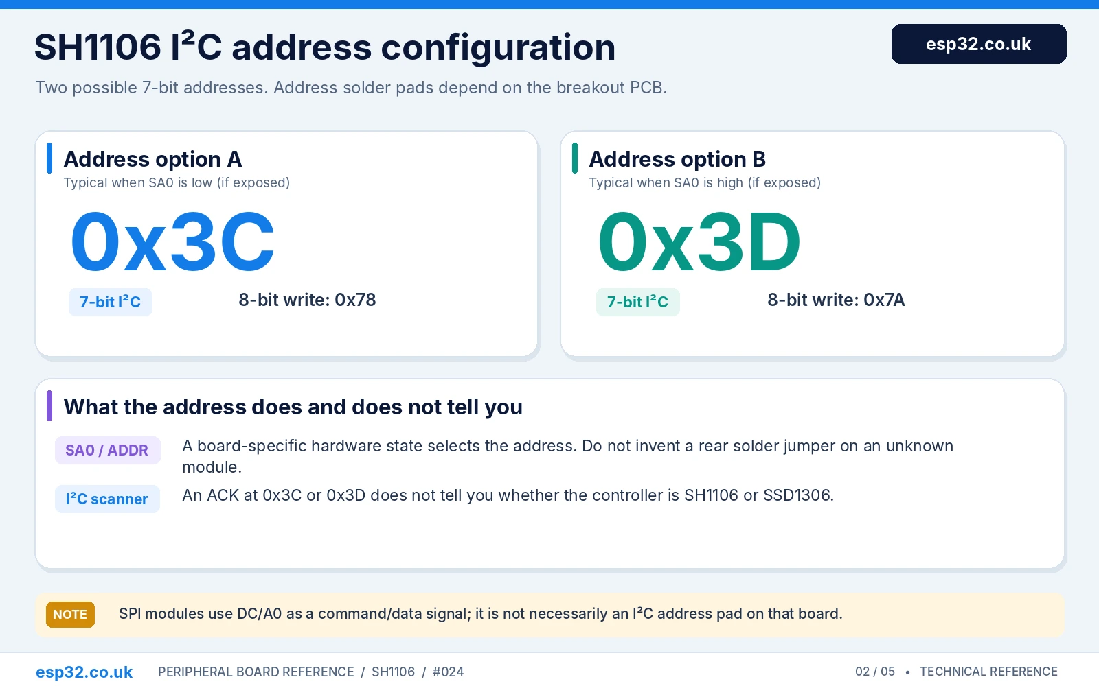
The SH1106 uses a 7-bit I²C address that is commonly either 0x3C or 0x3D, depending on the address-state hardware built into the module. Some boards expose an SA0, ADDR or resistorPrice-select option; many inexpensive four-pin boards have no practical user-accessible address jumper at all. There is no universal pair of rear solder pads for all SH1106 modules.
| Notation | Meaning |
|---|---|
0x3C | Common seven-bit Arduino I²C address |
0x3D | Alternative seven-bit address if the board supports it |
0x78 | Eight-bit write-address notation corresponding to seven-bit 0x3C |
0x7A | Eight-bit write-address notation corresponding to seven-bit 0x3D |
| SA0 / ADDR / resistor strap | Board-dependent setting; inspect the actual PCB schematic |
| D/C on SPI board | Data/command selection; not an I²C address pin in SPI operation |
A 1.3-inch panel does not force either I²C address. The Arduino scanner can tell whether some device acknowledges the address, but cannot distinguish SH1106 from SSD1306, CH1116 or another OLED controller. All may respond at the same 0x3C. Correct driver selection requires board documentation or a controlled test with the actual display.
Small ESP32 I²C scanner before installing display code
#include <Arduino.h>
#include <Wire.h>

void setup() {
  Serial.begin(115200);
  Wire.begin(21, 22);  // Classic ESP32: SDA, SCL
  Wire.setClock(100000);
  delay(250);
  for (uint8_t addr : {uint8_t(0x3C), uint8_t(0x3D)}) {
    Wire.beginTransmission(addr);
    if (Wire.endTransmission() == 0) {
      Serial.printf("I2C device at 0x%02X\n", addr);
    }
  }
}
void loop() {}
If neither address responds, check the board supply and ground, the chosen ESP32 GPIOs, SDA/SCL labels, whether pull-ups are present, and whether the module is actually a SPI board. If one responds, proceed with that address; a visible acknowledgement is not proof of the controller type.
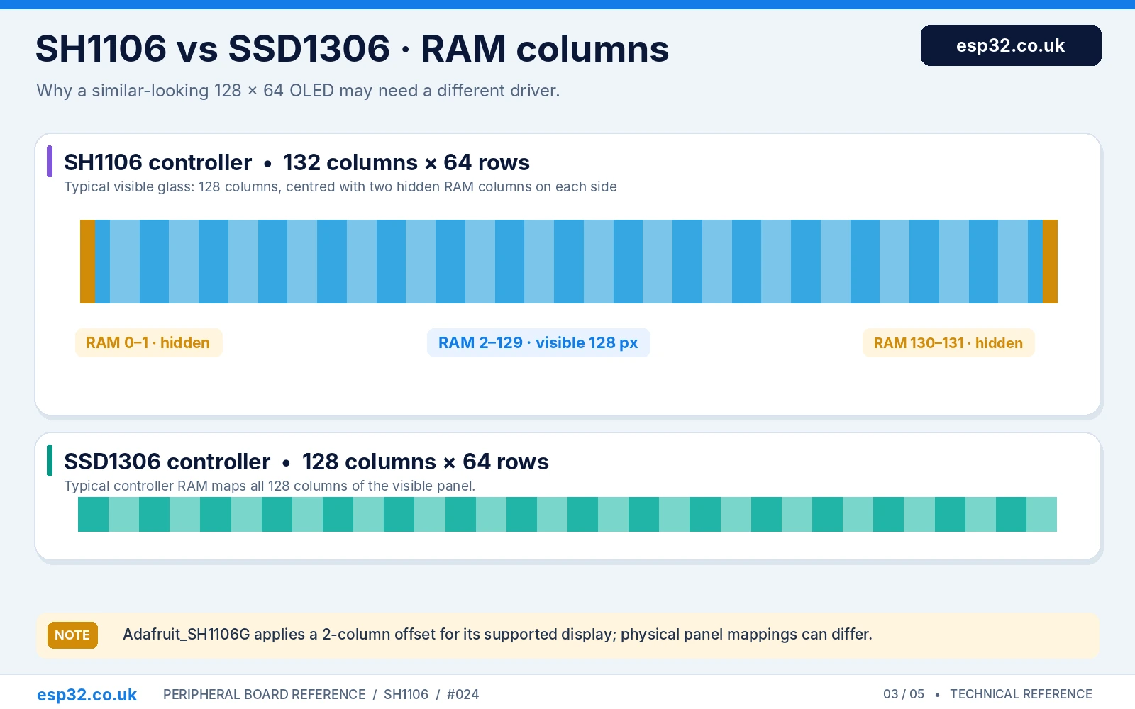
SH1106 versus SSD1306: the 132-column RAM offset
The classic SH1106 controller has 132 columns × 64 rows of internal display RAM, while the widely used SSD1306 has 128 columns × 64 rows. Typical 128-pixel-wide SH1106 glass is wired to a 128-column section of the larger 132-column memory, often columns 2–129. A driver that writes as though the display starts at column zero can create a two-pixel shift, clipped edges or a narrow vertical stripe. Other initialization-command differences can cause more severe corruption.
| Aspect | SH1106 | SSD1306 |
|---|---|---|
| Typical display | 1.3-inch, 128×64 | 0.96-inch, 128×64 (also 128×32) |
| Controller RAM | 132×64 bits | 128×64 bits |
| Common visible window | 128 columns inset in 132; often starts at column 2 | Usually columns 0–127 |
| Memory addressing | Page-oriented updates are characteristic | Supports page, horizontal and vertical addressing |
| Correct Adafruit library | Adafruit_SH110X | Adafruit_SSD1306 |
| ESP32 I²C address | Often 0x3C or 0x3D | Often 0x3C or 0x3D |
| Power and board headers | Depend on module PCB | Depend on module PCB |
The difference is in controller memory layout and initialization, not in the number of ESP32 wires. Changing SDA to another GPIO will not repair a two-pixel offset if you are still using the SSD1306 driver for an SH1106 module. The Adafruit_SH1106G implementation explicitly applies a two-column start offset for its supported display configuration. That is a library behaviour, not an instruction to physically shift the OLED.
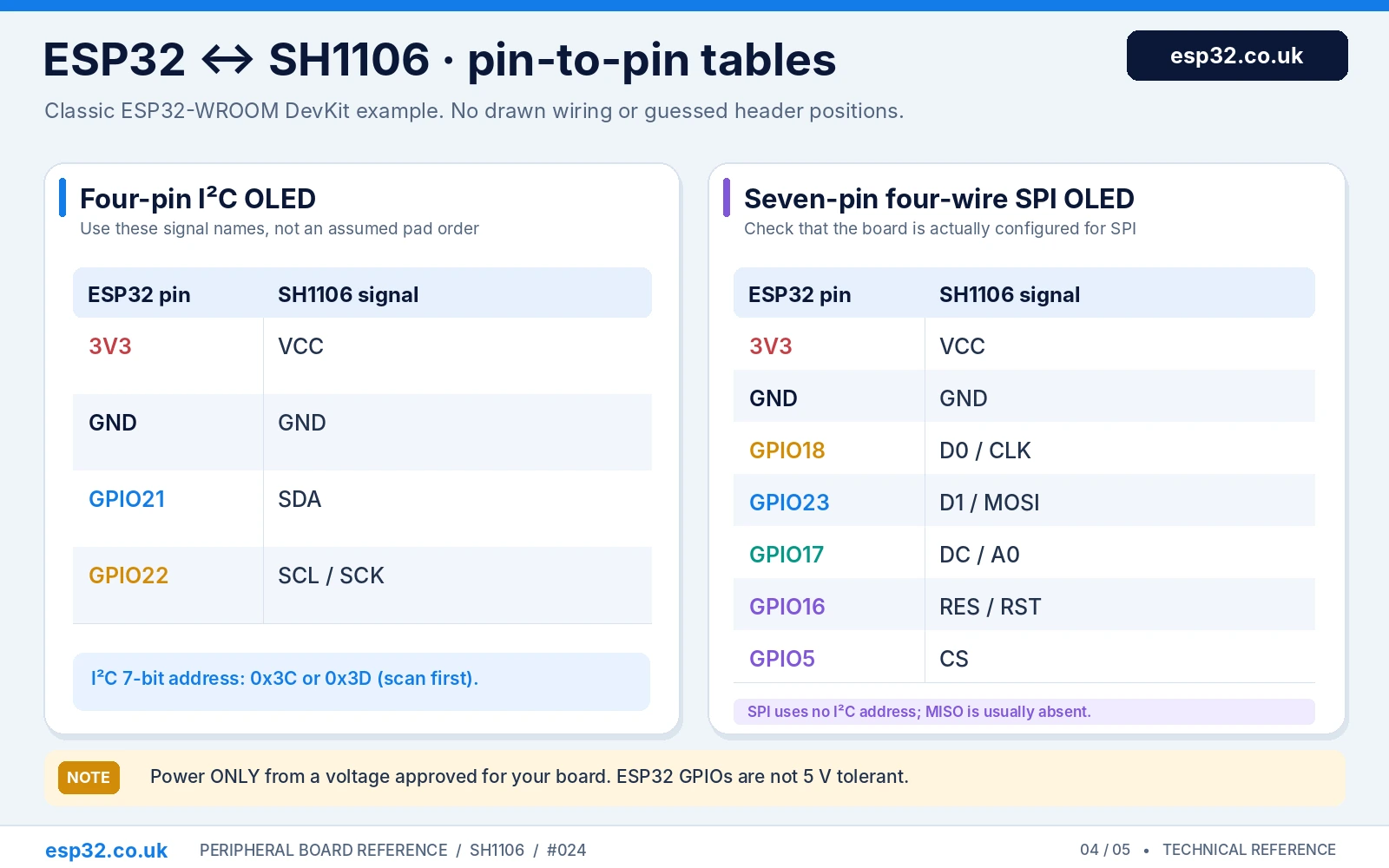
ESP32 to SH1106: wire-free I²C and SPI connection tables
The following tables specify logical nets and example GPIOs. They deliberately avoid coloured connection drawings: a wire that looks connected to the wrong physical contact is worse than no diagram at all. The pin order must still be read from the specific breakout silkscreen.
| Classic ESP32-WROOM | Four-pin I²C SH1106 | Purpose |
|---|---|---|
| 3V3 | VCC (compatible breakout only) | Supply |
| GND | GND | Common return |
| GPIO21 | SDA | I²C data |
| GPIO22 | SCL / SCK | I²C clock |
| Not required | No exposed DC / CS / RST on typical 4-pin board | I²C board configuration |
| Classic ESP32-WROOM | Seven-pin SPI SH1106 | Purpose |
|---|---|---|
| 3V3 | VCC (compatible breakout only) | Supply |
| GND | GND | Common return |
| GPIO18 | D0 / SCK | Clock |
| GPIO23 | D1 / MOSI | Display data |
| GPIO17 | DC / A0 | Data or command selection |
| GPIO16 | RES / RST | Hardware reset |
| GPIO5 | CS | Chip select |
| No connection | MISO often absent | Display is normally write-only |
ESP32-C3AliExpress price, S3, C6 and other boards use different GPIO arrangements. Update Wire.begin(SDA, SCL) or SPI.begin() to match your board; verify boot-strapping and peripheral conflicts before choosing other pins. Keep all bus pull-ups and logic levels within the ESP32’s 3.3 V limits.
Arduino IDE example: 1.3-inch SH1106 using Adafruit SH110X over I²C
Install Adafruit SH110X and Adafruit GFX Library with Arduino IDE Library Manager, including prompted Adafruit BusIO dependencies. The following code scans for 0x3C/0x3D, initialises a common 128×64 SH1106G module and displays a simple live uptime dashboard. It uses the verified API from the Adafruit SH110X library.
#include <Arduino.h>
#include <Wire.h>
#include <Adafruit_GFX.h>
#include <Adafruit_SH110X.h>

constexpr int OLED_SDA = 21;
constexpr int OLED_SCL = 22;
constexpr int WIDTH = 128;
constexpr int HEIGHT = 64;

Adafruit_SH1106G display(WIDTH, HEIGHT, &Wire, -1);
uint8_t displayAddress = 0;

uint8_t detectDisplayAddress() {
  for (uint8_t address : {uint8_t(0x3C), uint8_t(0x3D)}) {
    Wire.beginTransmission(address);
    if (Wire.endTransmission() == 0) return address;
  }
  return 0;
}

void setup() {
  Serial.begin(115200);
  Wire.begin(OLED_SDA, OLED_SCL);
  Wire.setClock(100000);

  displayAddress = detectDisplayAddress();
  if (displayAddress == 0) {
    Serial.println("No I2C OLED at 0x3C or 0x3D");
    while (true) delay(1000);
  }

  if (!display.begin(displayAddress, true)) {
    Serial.println("SH1106 framebuffer init failed");
    while (true) delay(1000);
  }
  Serial.printf("I2C OLED at 0x%02X\n", displayAddress);
}

void loop() {
  display.clearDisplay();
  display.setTextSize(1);
  display.setTextColor(SH110X_WHITE);
  display.setCursor(8, 4);
  display.println("esp32.co.uk/");
  display.drawLine(0, 18, 127, 18, SH110X_WHITE);

  display.setCursor(6, 28);
  display.print("Uptime: ");
  display.print(millis() / 1000);
  display.println(" s");

  display.setCursor(6, 46);
  display.printf("I2C: 0x%02X", displayAddress);
  display.display();  // Send framebuffer to OLED
  delay(1000);
}
This is an API-checked example for a common SH1106G-compatible 128×64 I²C board; it has not been physically bench-tested on every module revision. The call display.begin(displayAddress, true) accepts the seven-bit I²C address and enables reset if a valid reset pin was configured. With -1 as the reset pin, there is no separate MCU-controlled reset line. Some modules need specific reset timing from their PCB; follow that manufacturer’s guidance if the display will not initialise.
Why is display.display() necessary?
As with the SSD1306 library, Adafruit SH110X draws text and graphics into an ESP32 RAM framebuffer first. The display only changes when display.display() sends the buffer to the controller. A typical 128×64 monochrome framebuffer consumes 1,024 bytes of ESP32 RAM. The SH1106 controller’s own RAM is larger at 1,056 bytes, which is why the library handles a column offset internally.
Optional Arduino SPI example for a seven-pin module
Only use this sketch if the board is confirmed to have a four-wire SPI interface. A four-pin I²C-only SH1106 module will not run this code. The ESP32 hardware SPI uses GPIO18 for SCK, GPIO23 for MOSI, GPIO5 for CS, GPIO17 for DC and GPIO16 for RST in the example mapping.
#include <Arduino.h>
#include <SPI.h>
#include <Adafruit_GFX.h>
#include <Adafruit_SH110X.h>

constexpr int PIN_CS = 5;
constexpr int PIN_DC = 17;
constexpr int PIN_RESET = 16;

Adafruit_SH1106G display(128, 64, &SPI,
                        PIN_DC, PIN_RESET, PIN_CS);

void setup() {
  Serial.begin(115200);
  SPI.begin(18, 19, 23, PIN_CS); // SCK, MISO unused, MOSI, SS

  if (!display.begin(0, true)) { // Address ignored in SPI mode
    Serial.println("SPI SH1106 init failed");
    while (true) delay(1000);
  }

  display.clearDisplay();
  display.setTextSize(1);
  display.setTextColor(SH110X_WHITE);
  display.setCursor(8, 20);
  display.println("esp32.co.uk/");
  display.println("SH1106 over SPI");
  display.display();
}
void loop() {}
SPI displays do not have an I²C slave address: the zero supplied to begin() is ignored for SPI. If an SPI sketch prints the success message but the screen is dark, verify its interface mode, D/C, CS and reset wiring by reading the board labels and revisiting the lookup table. Do not attempt to fix an SPI-only module by running an I²C scanner.
SH1106 troubleshooting and common display problems
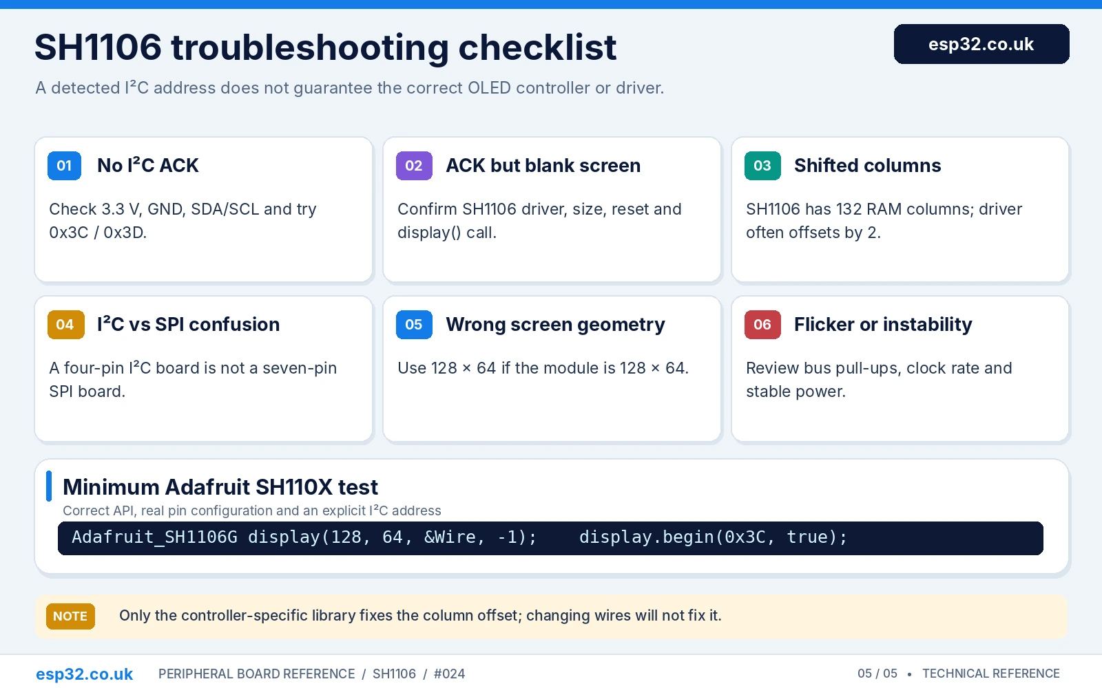
| Symptom | Likely reason and fix |
|---|---|
| No 0x3C/0x3D device detected | Incorrect 3.3 V supply, ground, SDA/SCL mapping, missing pull-ups, incorrect GPIO numbers, or a SPI-only module |
| Device responds but screen is black | Wrong driver, reset issue, contrast/display init, inappropriate board voltage, or missing display.display() |
| Two-pixel horizontal shift or vertical strip | SH1106 driven as SSD1306; use a compatible SH1106 driver handling the 132-column RAM offset |
| Garbled display or top eight rows only | Driver command set or buffer/page handling mismatch; confirm actual controller |
| Rows or columns appear mirrored | Module orientation/segment-remap assumptions differ; use a driver and initialization matching the actual panel |
| A supposed 1.3-inch OLED works as SSD1306 | Some 1.3-inch products genuinely use SSD1306 or SSD1309; do not choose a chip solely from the screen size |
| Multiple I²C displays collide | Both answer at the same seven-bit address; address-select option where available or separate mux channels |
| 7-pin board not found by I²C scanner | Likely SPI module; D0/D1/CS/DC/RES signal functions differ |
| Display fades or fixed image ghosts | OLED pixel ageing from static bright content; use moderate contrast and blank it when idle |
| ESP32 unstable / OLED hot | Potential wrong polarity or voltage, 5 V I²C pull-ups, or damaged module; disconnect and inspect |
Can I tell SH1106 from SSD1306 with an I²C scan?
No. Both controllers can acknowledge the same seven-bit address. An I²C scan confirms that a slave responds; it is not a reliable chip-identification test. Use the vendor documentation, readable controller markings if available, or a supported display driver and a clear edge-to-edge test pattern. Some module listings are simply wrong.
SH1106 versus SSD1306: when should you choose each?
An SSD1306 board is a reasonable default when you want a ubiquitous, small OLED and well-established examples. A 1.3-inch SH1106 module can be easier to read from a distance while providing the same nominal 128×64 visible resolution. Neither controller offers colour or high pixel density. The primary integration cost of the SH1106 is getting the controller-specific library and initialization right.
For a design that needs more text, menus or charts, consider an appropriately supported TFT or a larger OLED rather than assuming the extra 0.34-inch diagonal provides more pixels. The SH1106 often has the same 8,192 visible monochrome pixels as a 0.96-inch SSD1306.
Frequently asked questions
Is SH1106 I²C address 0x3C or 0x3D?
Both are possible. Most inexpensive modules use 0x3C, while other configurations may use 0x3D. Run an I²C scanner and use the detected seven-bit value in code. The 8-bit write notation 0x78/0x7A should not be supplied to Arduino Wire.
Why is the image two pixels to the side?
A typical 128-wide SH1106 panel is mapped inside the controller’s 132-wide RAM with an offset, often two columns. Code that assumes an SSD1306 memory layout can cause that displacement. Use a SH1106-specific driver, not a wiring workaround.
Can SH1106 use Adafruit GFX?
Yes. Install Adafruit SH110X together with Adafruit GFX. The SH110X driver handles the display-controller specifics, while GFX provides text and shape drawing functions.
Do four-pin SH1106 OLEDs support SPI?
A typical four-pin module is wired for I²C and exposes no CS/DC lines. The bare controller may support SPI, but you need a breakout explicitly designed or documented for SPI to use it.
Does SH1106 have a 5 V-safe ESP32 interface?
The bare controller is not a 5 V logic device. Some modules have input regulators but not level shifting. Verify the exact module; for direct ESP32 use, a documented 3.3 V-compatible module powered at 3.3 V is the safest default.
Can SH1106 and SSD1306 coexist on one I²C bus?
Yes, provided their addresses differ or they are isolated through different I²C buses/multiplexer channels. Their graphics libraries differ even when their signal connections look alike.
Sources and related esp32.co.uk/ guides
- Sino Wealth SH1106 datasheet — 132×64 RAM, logic and OLED supplies, I²C/SPI modes and commands.
- Adafruit SH110X library — current Arduino source, display class and example projects.
- Adafruit_SH1106G API — constructor and begin() arguments.
- Adafruit I²C address reference — OLED address alternatives 0x3C and 0x3D.
- U8g2 graphics library — alternative driver supporting SH1106 and many other controllers.
- esp32.co.uk/ I²C scanning guide — useful when an OLED does not respond.
- esp32.co.uk/ TCA9548A guide — isolating devices with colliding I²C addresses.
Editorial note: This esp32.co.uk/ reference covers common SH1106G-compatible I²C and SPI breakout families; no single generic PCB outline or solder-jumper placement is universal. The code has been checked against the published Adafruit SH110X API but not bench-tested on every carrier. The associated technical images will have visible esp32.co.uk/ branding and will contain pinouts and connection tables, never decorative electrical wires.