A button press can generate several electrical transitions before the contacts settle. On an STM32PriceAliExpress price, an external interrupt can report those transitions quickly, but the application still has to decide what counts as a press. If you toggle an LEDPrice in the interrupt callback, one press can toggle it several times and leave it looking as though nothing happened.
In this guide, you will build a Blue PillPriceAliExpress price lab that makes the distinction visible. A push buttonAliExpress price on PB8 drives EXTI line 8. The shared interrupt handler calls the STM32F1 HAL, and a short callback records that activity occurred. The main loop then waits for a stable change before toggling the onboard LED on PC13. Three debugger counters let you compare raw interrupt callbacks with accepted presses and releases.
Quick answer. On an STM32F103C8T6, set PB8 to external interrupt mode on both edges with a pull-up. Connect a normally open push button between PB8 and GND. Enable the EXTI lines 5 to 9 interrupt in STM32CubeMX and confirm that EXTI9_5_IRQHandler() dispatches HAL_GPIO_EXTI_IRQHandler(GPIO_PIN_8). Keep the callback short and apply the debounce policy in the main loop.
What happens between a GPIO edge and your callback
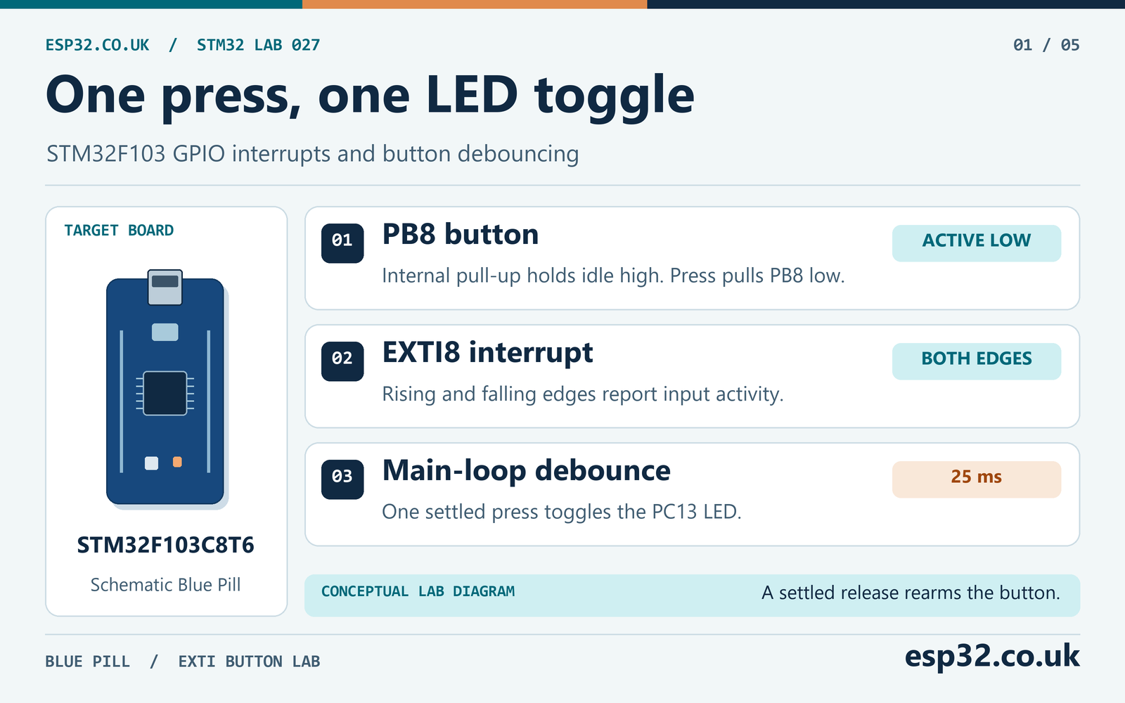
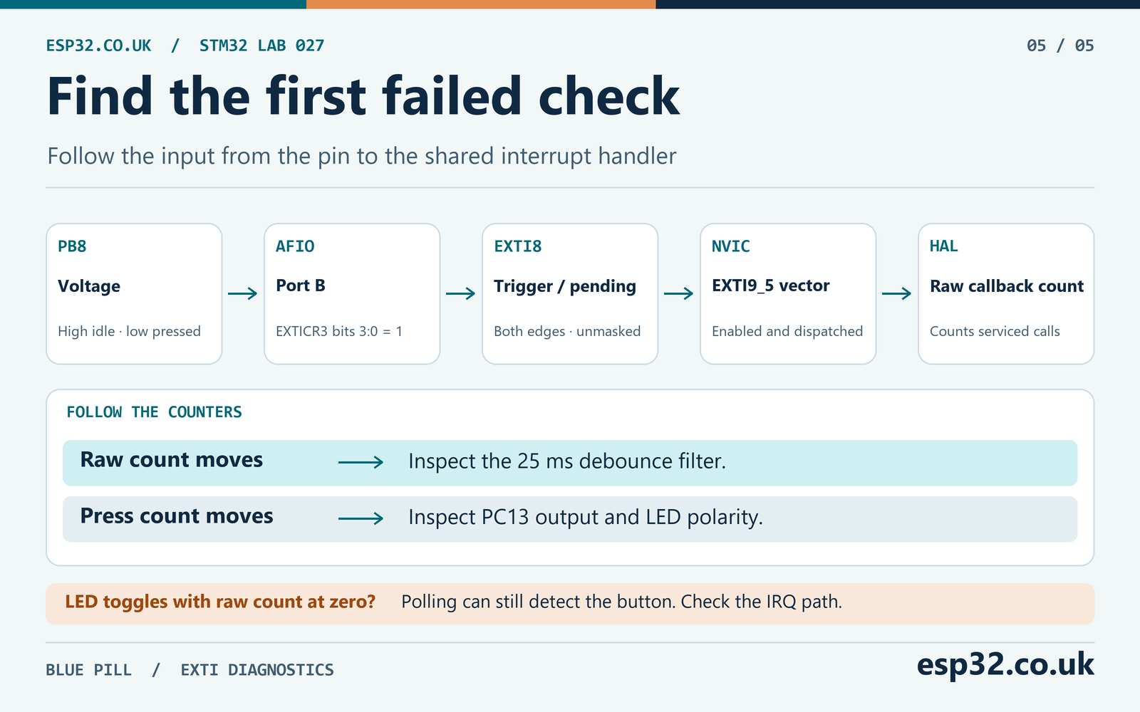
Treat the path as a series of gates. The input buffer observes a voltage on the pin. The alternate-function I/O block selects which port supplies a given EXTI line. The EXTI controller detects the configured edge and records the pending request. The Nested Vectored Interrupt Controller, or NVIC, decides when the processor can service its vector. The interrupt handler then dispatches the line to HAL, which clears its pending bit and calls your code. A mistake at any gate can leave the application silent even when PB8 changes voltage.
The line number follows the pin number. PB8 goes through EXTI8, as would PA8 if you routed port A to that line. Only one GPIO port can feed EXTI8 at a time. PB8 and PB9 can both be used because they occupy distinct lines. They still share the same processor vector, so the vector handler must account for both pending sources. On this F1 device, GPIO port selection lives in AFIO. Later families can use a different block, so consult the manual for the actual MCU. STM32F1 reference manual RM0008, GPIO/AFIO and interrupts chapters
| GPIO EXTI lines | NVIC interrupt name on STM32F103C8 | Handler name |
|---|---|---|
| 0 | EXTI0_IRQn | EXTI0_IRQHandler |
| 1 | EXTI1_IRQn | EXTI1_IRQHandler |
| 2 | EXTI2_IRQn | EXTI2_IRQHandler |
| 3 | EXTI3_IRQn | EXTI3_IRQHandler |
| 4 | EXTI4_IRQn | EXTI4_IRQHandler |
| 5–9 | EXTI9_5_IRQn | EXTI9_5_IRQHandler |
| 10–15 | EXTI15_10_IRQn | EXTI15_10_IRQHandler |
The names in the table are identifiers, and the order of the digits matters. If you invent EXTI8_IRQHandler, the compiler can accept the function while the startup vector still points elsewhere. Use the CubeMX-generated vector handler and check the device header if you change pins. The vector handles a group, while the callback receives a pin mask for the individual dispatch. ST STM32F103 medium-density CMSIS device header
Interrupt mode and event mode
The EXTI controller can expose a line as an interrupt, an event or both through separate masks. For this lab, choose the GPIO interrupt mode so the NVIC and handler are part of the path. The event facility serves different use cases, including designs that wake a core waiting for an event. A CubeMX selection that says GPIO event can leave you with a pin that changes normally but never calls your interrupt handler.
The software should also distinguish the words edge, callback and application event. An edge is a change at the digital input. A callback is a software dispatch for a pending line. An application event is the result of the debounce policy. A clean digital generator and a mechanical switch can yield very different callback counts for the same number of useful actions.
Wire an active-low push button on PB8
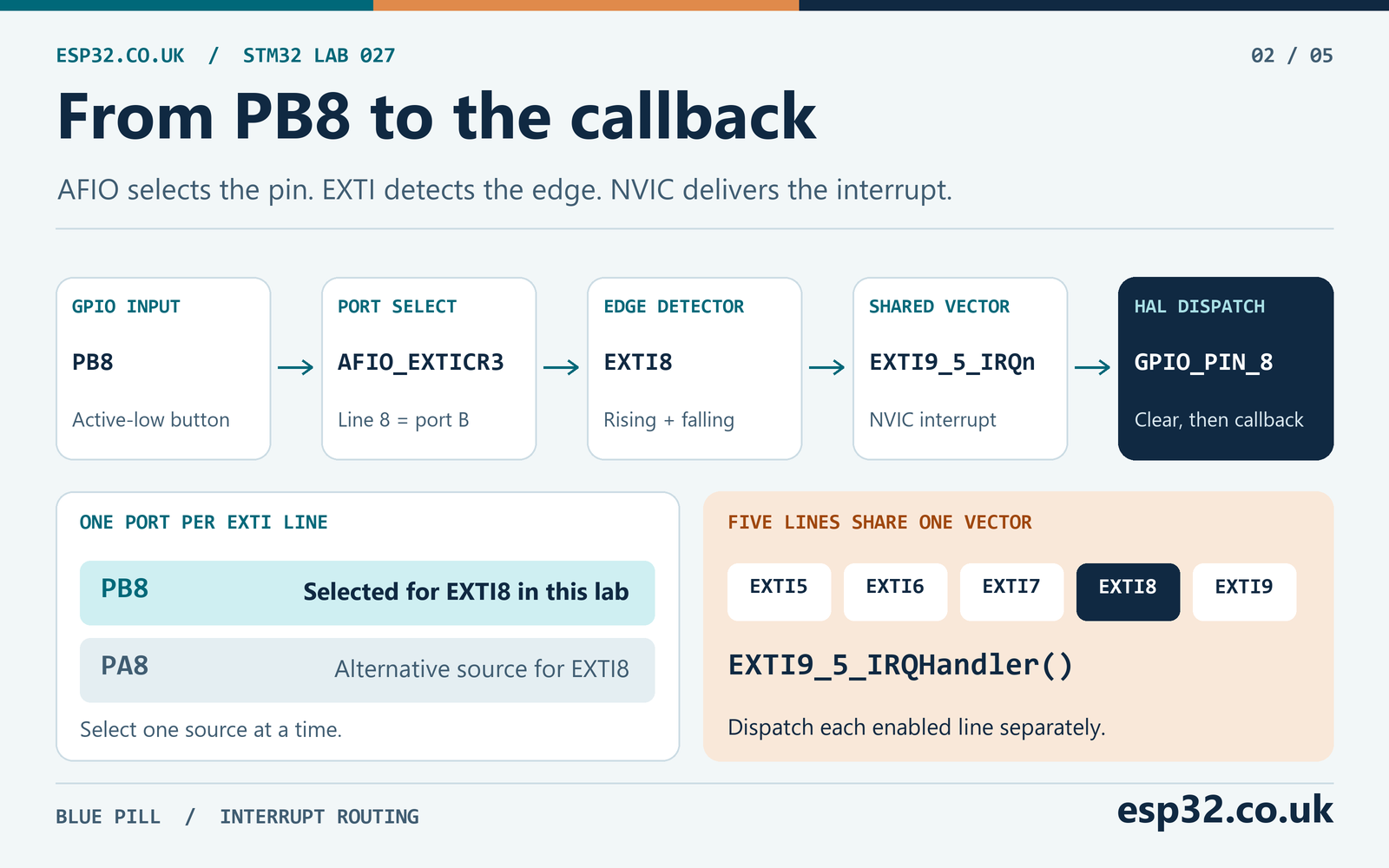
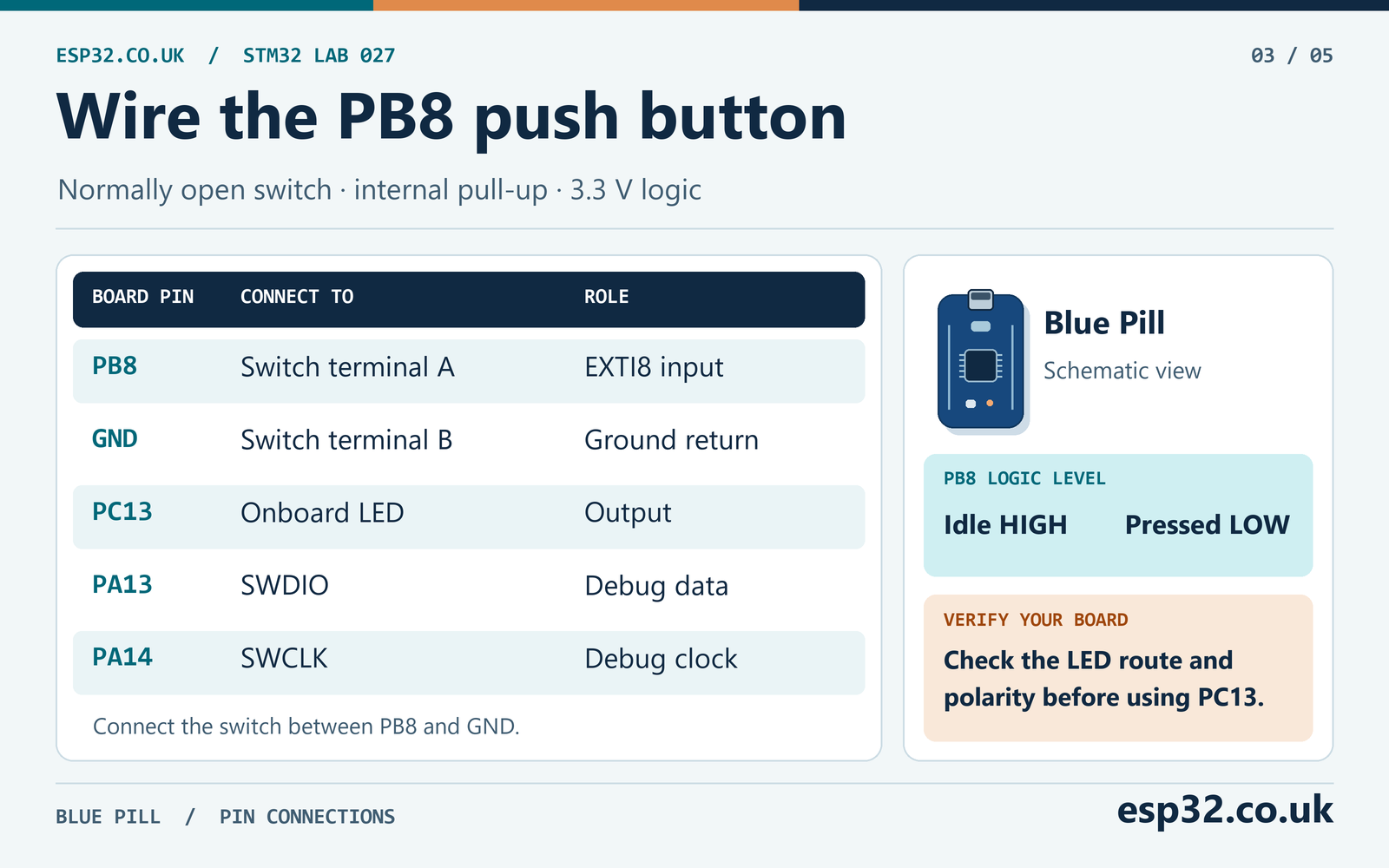
Use a Blue Pill with an STM32F103C8T6, an SWD programmer, a normally open momentary switch and short jumper leads. With the board unpowered, connect one side of the switch to PB8 and the other to GND. On a four-leg tactile switch, two pins on each side are commonly already joined. Use a continuity meter to identify contacts that connect only when pressed. If you choose the two permanently connected legs, PB8 will read low continuously.
The internal pull-up holds PB8 high while the contacts are open. Pressing connects PB8 to ground, producing a falling edge. Releasing opens the connection, allowing the pull-up to raise the input and produce a rising edge. Configure PB8 as an input before operating the switch. An output configured high could be shorted through the button.
| Connection or setting | Lab choice | Expected observation |
|---|---|---|
| Switch terminal A | PB8 | Input changes with the switch |
| Switch terminal B | GND | Press pulls the input low |
| PB8 bias | Internal pull-up | Idle input is high |
| PC13 | Onboard LED output | Active low on a typical Blue Pill |
| PA13 and PA14 | SWDIO and SWCLK | Keep available for programming |
| Instrument ground | Board GND | Common reference for an optional probe |
Many Blue Pill boards connect their indicator LED to PC13 so a low output lights it. Verify your board’s LED connection and polarity first. Set the initial PC13 output high so this lab starts with the LED off on that arrangement. If your board uses a different LED, update the output pin in both CubeMX and the module. For board setup and the basic LED experiment, see the earlier series guide. STM32 GPIO and HAL LED tutorial
PB8 can also be used for remapped I²C1 SCL and other functions. Choose a free pin when merging this lab into another project. The package pin number, the label on the board header and the EXTI line number describe different things. This lab uses the board label PB8 and EXTI8. ST STM32F103x8/xB datasheet
Start on the bench with the button close to the board. An internal pull-up is convenient for this short connection. A long cable can collect interference and should be designed with a defined return path, suitable input protection and an appropriate bias network. If adding an external pull-up, connect it to the board’s 3.3 V rail. Check logic levels at the MCU pin when changing the input circuit. Blue Pill GPIO voltage guide
Configure STM32CubeMX and check the generated handler
Create an STM32CubeMX project for the STM32F103C8Tx. Enable Serial Wire under SYS to preserve the SWD pins. A normal 1 ms HAL timebase is sufficient for this experiment. You can keep an ordinary working clock configuration. The lab uses milliseconds from HAL rather than deriving timing from a hardcoded 72 MHz assumption.
Select the PB8 pin and assign GPIO EXTI8. In GPIO settings, select external interrupt mode with rising and falling edge detection and choose an internal pull-up. Set PC13 as a push-pull GPIO output with the initial level high and low output speed. Enable the NVIC interrupt for EXTI lines 5 to 9. Generate a C project for STM32CubeIDE or your usual CubeF1 toolchain.
| CubeMX item | Value for the lab |
|---|---|
| Target device | STM32F103C8Tx |
| Debug connection | Serial Wire |
| PB8 selection | GPIO_EXTI8 |
| PB8 trigger | Rising and falling edges |
| PB8 pull | Pull-up |
| PC13 output | Push-pull, initial high, low speed |
| NVIC vector | EXTI line[9:5] interrupts enabled |
| Timebase | HAL tick advancing in milliseconds |
Open the generated gpio.c or the GPIO section in main.c. Confirm that the GPIOB and GPIOC clocks are enabled and that PB8 uses GPIO_MODE_IT_RISING_FALLING with GPIO_PULLUP. In the STM32F1 HAL, GPIO interrupt initialisation also enables the AFIO clock and updates the line’s source selection. The NVIC configuration is separate. Both pieces must be present.
In Core/Src/stm32f1xx_it.c, verify that CubeMX generated a handler equivalent to the one below. Keep one definition of the function. If code generation already supplied it, this is a reference for inspection.
void EXTI9_5_IRQHandler(void)
{
    HAL_GPIO_EXTI_IRQHandler(GPIO_PIN_8);
}
The HAL helper checks whether the requested line is pending, clears it and then calls HAL_GPIO_EXTI_Callback(). The lab defines a replacement for the weak default callback. That replacement can be in any compiled C source file with the correct signature. If another module already defines the callback, consolidate the dispatch in one place and preserve each pin’s handling. STM32F1 HAL GPIO implementation v1.1.10
Inspect the generated files after changing the CubeMX configuration. Switching a GPIO to polling can remove its interrupt route or handler call. Renaming a pin can change the macro in the handler without changing the port being selected. Keep application logic in separately compiled modules and place the include and function calls in generated user-code sections so regeneration retains them.
Why a delay inside the interrupt callback causes trouble
Contact bounce is a sequence of real transitions. They may arrive close together, and each press can produce a different pattern. A delay inside the callback makes other work wait while the handler is active. It can also hang if the delay needs a tick interrupt that cannot preempt the current interrupt at the configured priorities.
The callback in this lab only sets a flag and increments a diagnostic counter. A flag is sufficient because the debounce policy asks whether there was activity since the last sample. It has no need to replay every bounce. The main loop samples the input, remembers when the current candidate state became quiet and commits the change after 25 ms of observed stability.
A fixed interval after the first edge is another possible policy. It is simple, but it can accept an early transition before the input has settled or suppress a legitimate subsequent transition during the lockout. A stable-state policy tracks both directions, so it can require a settled release before accepting the next press. That fits a button where the application action should happen only once per press.
| State | Meaning in the lab |
|---|---|
| Raw pin | Current sampled logic level on PB8 |
| Candidate | Possible new pressed or released state |
| Candidate age | Milliseconds since the candidate was observed or restarted |
| Stable state | Last accepted logical button state |
| Application event | Accepted transition to pressed or released |
The debouncer is deliberately conservative. If an interrupt callback occurred since the previous sample, the candidate’s clock restarts at the current sample. A bounce that returned the pin to the same level between polls can still delay acceptance. If a sampled level differs from the current candidate, that also restarts the interval, including when the interrupt path has been misconfigured. This second path makes a raw callback counter valuable during commissioning.
Add the debouncer and the HAL application module
Copy the two headers to Core/Inc and the two C files to Core/Src. The debounce module only depends on the standard C Boolean and fixed-width integer types. It takes an input sample, a notification flag and a timestamp. The HAL module owns the lab’s binding to PB8, PC13 and the interrupt callback.
The header defines the accepted transition values and holds the stable state, candidate state and candidate start time.
#ifndef BUTTON_DEBOUNCE_H
#define BUTTON_DEBOUNCE_H

#include <stdbool.h>
#include <stdint.h>

typedef enum {
    BUTTON_NO_EVENT,
    BUTTON_PRESSED,
    BUTTON_RELEASED
} ButtonEvent;

typedef struct {
    bool stable_pressed;
    bool candidate_pressed;
    uint32_t candidate_since_ms;
} ButtonDebounce;

void ButtonDebounce_Init(ButtonDebounce *button, bool pressed, uint32_t now_ms);
ButtonEvent ButtonDebounce_Update(ButtonDebounce *button, bool pressed,
                                  bool edge_seen, uint32_t now_ms);

#endif
The implementation initialises both states to the first observed level. When the input is already held at reset, that initial condition does not generate a press event. Release the button, let the release settle and press again to toggle the LED. An application that must count a button held at boot needs an explicit startup policy.
#include "button_debounce.h"

#define BUTTON_SETTLE_MS 25U

void ButtonDebounce_Init(ButtonDebounce *button, bool pressed, uint32_t now_ms)
{
    button->stable_pressed = pressed;
    button->candidate_pressed = pressed;
    button->candidate_since_ms = now_ms;
}

ButtonEvent ButtonDebounce_Update(ButtonDebounce *button, bool pressed,
                                  bool edge_seen, uint32_t now_ms)
{
    if (edge_seen || pressed != button->candidate_pressed) {
        button->candidate_pressed = pressed;
        button->candidate_since_ms = now_ms;
    }

    if (button->candidate_pressed == button->stable_pressed ||
        (uint32_t)(now_ms - button->candidate_since_ms) < BUTTON_SETTLE_MS) {
        return BUTTON_NO_EVENT;
    }

    button->stable_pressed = button->candidate_pressed;
    return button->stable_pressed ? BUTTON_PRESSED : BUTTON_RELEASED;
}
The lab header exposes two calls for the generated application.
#ifndef EXTI_LAB_H
#define EXTI_LAB_H

void ExtiLab_Init(void);
void ExtiLab_Poll(void);

#endif
The lab polls at most once per HAL millisecond. It takes the activity flag, the input sample and the timestamp in a short critical section. The old interrupt-mask state is restored, so this helper does not unexpectedly enable interrupts when the caller entered with them disabled. The callback and the main loop share only the activity flag. The two debounced counters and the LED belong to the main loop.
#include "button_debounce.h"
#include "exti_lab.h"
#include "stm32f1xx_hal.h"

static volatile uint32_t edge_seen;
static ButtonDebounce button;
static uint32_t last_poll_ms;

/* Debugger counters. The callback owns the first and the main loop owns the rest. */
volatile uint32_t exti_lab_raw_irq_count;
volatile uint32_t exti_lab_press_count;
volatile uint32_t exti_lab_release_count;

void HAL_GPIO_EXTI_Callback(uint16_t pin)
{
    if (pin == GPIO_PIN_8) {
        edge_seen = 1U;
        exti_lab_raw_irq_count++;
    }
}

void ExtiLab_Init(void)
{
    last_poll_ms = HAL_GetTick();
    bool pressed = HAL_GPIO_ReadPin(GPIOB, GPIO_PIN_8) == GPIO_PIN_RESET;
    ButtonDebounce_Init(&button, pressed, last_poll_ms);
}

void ExtiLab_Poll(void)
{
    if ((uint32_t)(HAL_GetTick() - last_poll_ms) < 1U) {
        return;
    }

    uint32_t saved_primask = __get_PRIMASK();
    __disable_irq();
    bool saw_edge = edge_seen != 0U;
    edge_seen = 0U;
    bool pressed = HAL_GPIO_ReadPin(GPIOB, GPIO_PIN_8) == GPIO_PIN_RESET;
    uint32_t now_ms = HAL_GetTick();
    __set_PRIMASK(saved_primask);
    last_poll_ms = now_ms;

    ButtonEvent event = ButtonDebounce_Update(&button, pressed, saw_edge, now_ms);
    if (event == BUTTON_PRESSED) {
        exti_lab_press_count++;
        HAL_GPIO_TogglePin(GPIOC, GPIO_PIN_13);
    } else if (event == BUTTON_RELEASED) {
        exti_lab_release_count++;
    }
}
In the generated main.c, add the header in the Includes user section. Call the initialiser after the generated GPIO setup and call the poll function in the existing infinite loop. These lines go in their corresponding locations, rather than being pasted as a single standalone source file.
/* USER CODE BEGIN Includes */
#include "exti_lab.h"
/* USER CODE END Includes */

/* USER CODE BEGIN 2: after MX_GPIO_Init() */
ExtiLab_Init();
/* USER CODE END 2 */

/* Inside the existing while (1) loop, in a USER CODE section */
ExtiLab_Poll();
The first build should use a simple main loop. Make sure all four files are part of the project and the HAL GPIO driver is included. Put a breakpoint in the application’s error handler if it fails to start. During a timing test, let the target run continuously and use live expressions or a logic analyser. A paused target can allow hardware pending flags and software time to behave differently from normal execution.
Read the debounce timing and choose a threshold
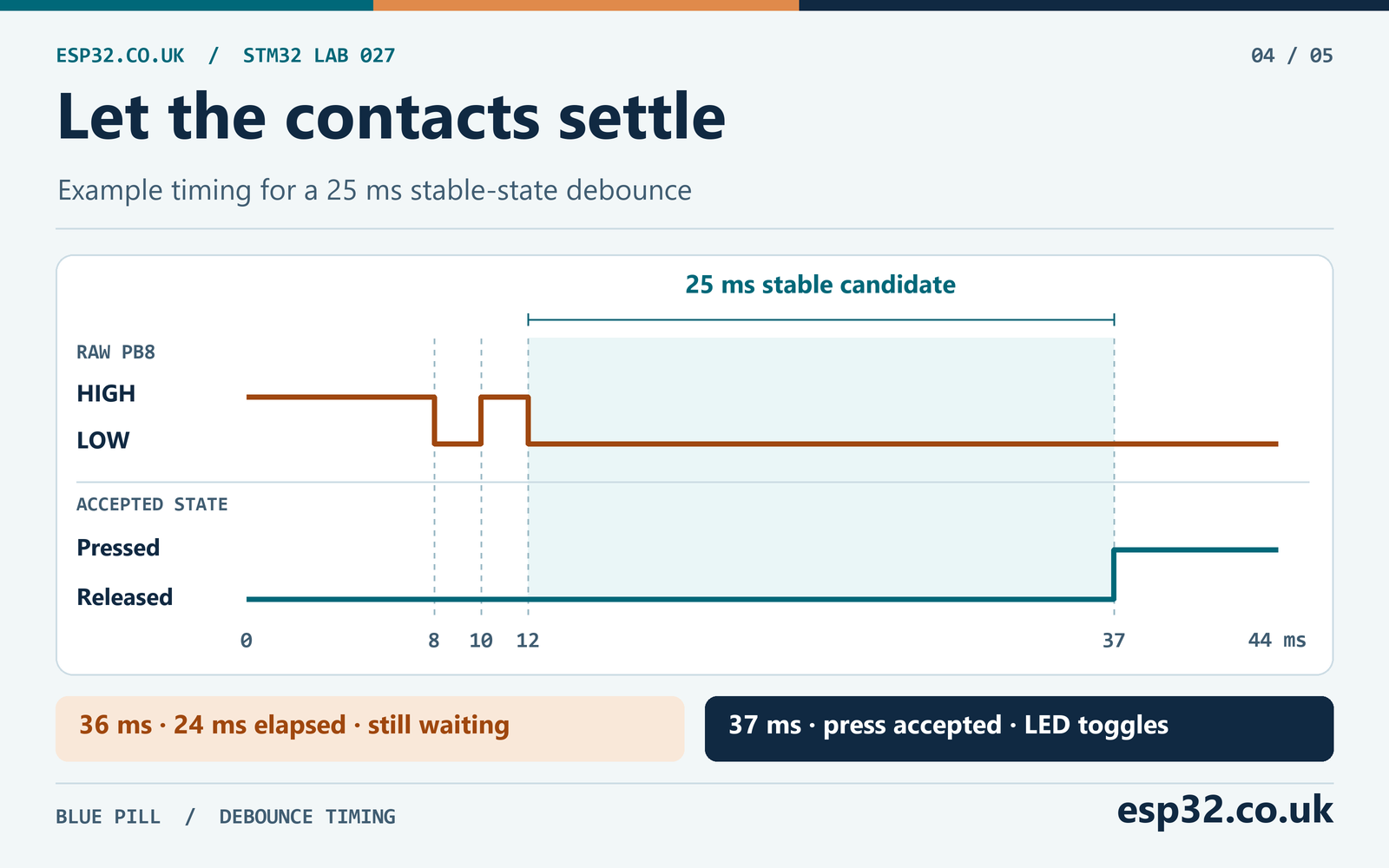
Suppose the last contact transition is observed at a sample taken at 12 ms. The earliest sample that can accept that candidate is at 37 ms, provided every subsequent observation supports the same level and the callback reports no further activity. The logical latency is measured from the last observed disturbance. It includes the settle interval and the time until the next service of the main loop.
| Observation | Time | Debouncer result |
|---|---|---|
| Press first observed | 8 ms | Candidate becomes pressed |
| Contact opens briefly | 10 ms | Candidate changes back |
| Input settles low and is observed | 12 ms | Pressed candidate starts again |
| Low sample with no new activity | 36 ms | 24 ms elapsed, still waiting |
| Low sample with no new activity | 37 ms | Press accepted, LED toggles |
| Button held low | 100 ms | Stable state unchanged |
A 25 ms threshold is a starting value for a human-operated switch. Measure the worst practical bounce on the actual hardware and choose a threshold that fits both the switch and the required response. If a quick tap ends before the pressed state can be accepted, the lab discards it. If the application needs short pulses, use a suitable sensor, hardware conditioning or a different detection policy.
The millisecond counter is a 32-bit unsigned value. At a 1 ms timebase it wraps after about 49.7 days. Unsigned subtraction gives the correct short elapsed interval across that wrap. For example, a candidate starting at 0xFFFFFFF0 has aged 25 ms at 0x00000009. A direct test against a future absolute timestamp can fail at the wrap. This reasoning assumes the interval is much shorter than the full counter cycle.
Sample cadence also matters. The one-millisecond guard limits how often the main loop polls. It cannot force the loop to return on time. A long blocking serial transfer can postpone a poll and increase button latency. Keep the foreground responsive, or move sampling to a separately designed periodic task if you need a tighter observation schedule. The timer tutorial covers the hardware timebase side of that choice. STM32 timers and PWM tutorial
Handle shared vectors and clear pending bits correctly
If you add a second button on PB9, configure EXTI9 separately and ensure the shared handler dispatches both line masks. Each HAL call tests the matching pending bit. Passing a combined mask would give the callback a combined value and can clear both bits in one operation. Keep separate calls when each pin has its own handling.
/* Reference pattern for a future two-line project. */
void EXTI9_5_IRQHandler(void)
{
    HAL_GPIO_EXTI_IRQHandler(GPIO_PIN_8);
    HAL_GPIO_EXTI_IRQHandler(GPIO_PIN_9);
}
Add a second debounce state and a separate activity flag if you want PB9 to produce its own logical events. Merely enabling its line can give a vector entry without a useful response. If an enabled line’s pending flag remains set because the shared handler never dispatches it, the processor can repeatedly re-enter the handler and leave little time for main-loop work.
EXTI_PR uses write-one-to-clear semantics. For low-level diagnostics, a direct write of a one-bit mask clears only that line. A read-modify-write such as EXTI->PR |= GPIO_PIN_8 can write back other ones that were already pending, clearing unrelated sources. Let HAL acknowledge the line in the normal implementation. A direct clear is useful only when intentionally writing your own handler or clearing a controlled test condition. RM0008, EXTI pending register
/* Register-level acknowledgement for EXTI8, if you own the handler. */
EXTI->PR = GPIO_PIN_8;
Clearing a pending bit in the NVIC and clearing the EXTI source flag are separate operations. A request can be asserted again if the source stays pending. In a debugger, check the GPIO input state first, then AFIO source selection, trigger settings and the EXTI mask. Use the peripheral pending flag and vector handler to narrow the remaining failure.
Read the EXTI8 setup in the debugger
The STM32F103 register view gives you a useful snapshot of the configuration. Inspect the low four bits of AFIO_EXTICR3, which select the port for line 8. In the lab they should contain 1 for port B. A zero selects port A. If PB8 changes at the input and this field still selects port A, the EXTI controller is watching a different pad.
| Register or state | Expected lab setting | What it tells you |
|---|---|---|
| GPIOB_IDR bit 8 | High released, low pressed | Sampled electrical input |
| AFIO_EXTICR3 bits 3:0 | 1 | Port B selected for EXTI8 |
| EXTI_RTSR bit 8 | 1 | Rising edge armed |
| EXTI_FTSR bit 8 | 1 | Falling edge armed |
| EXTI_IMR bit 8 | 1 | Interrupt request unmasked |
| EXTI_EMR bit 8 | 0 | GPIO configured for interrupt mode |
| EXTI_PR bit 8 | Normally clear after service | Transient line request |
| NVIC EXTI9_5 enable | Enabled | Shared vector can be delivered |
The pending flag can be too brief to catch by repeatedly refreshing the register view while the target runs. The HAL helper clears it before it calls the callback. If you need to see it asserted, inspect it at the beginning of the vector handler during a controlled test. Observe the generated register settings before making manual writes, which can change the conditions you are trying to diagnose.
If EXTI8 and EXTI9 are both pending at entry, the two HAL calls process them in the order written in the handler. That order is a software decision. It does not establish which physical edge happened first. If the application requires a chronology, capture timestamps using a peripheral designed for that purpose.
An EXTI pending bit represents a request, not a queue of timestamps. Multiple edges while a request is pending can coalesce. An edge can also occur while software is servicing the source. The raw counter in this lab counts callback deliveries and has no claim to count every electrical transition. For a pulse train where exact frequency or edge timing matters, consider timer input capture or hardware counting with a defined service budget.
Set priorities and share data without adding delay
On Cortex-M, lower numeric priority values correspond to higher urgency within the configured priority grouping. Preemption priority determines whether one interrupt can interrupt another. Subpriority orders pending interrupts at the same preemption level. Changing grouping affects the rest of the application, so check its existing configuration before assigning priorities. For this bench test, keep the EXTI callback short and use the generated priority setting. ST Cortex-M3 programming manual PM0056
The shared activity flag is volatile so the compiler performs each access. Volatile alone cannot make a read followed by a clear indivisible. If a callback runs between those two operations, the clear can erase a newly posted notification. The main loop briefly masks interrupts around the transfer and restores the mask as soon as it has the snapshot. An edge that becomes pending during the section can be serviced after interrupts are restored, subject to the peripheral’s normal pending-bit behaviour.
Keep that section short enough for the rest of the application. It contains no waiting, logging, LED access or debounce calculations. If a more complex project already uses an RTOS, use its supported ISR-to-task mechanism and check its interrupt priority rules. Copying this polling integration directly into an RTOS task may interact with the scheduler’s existing ownership of timing and critical sections.
For a button, a Boolean mailbox is adequate. For encoder counts, a high-rate tachometer or a timestamped event log, choose the data structure and peripheral based on the required throughput and loss policy. A finite queue still needs an overflow policy. Separately consider whether the producer can keep up at the input’s worst-case rate and whether the consumer can drain the queue between bursts.
Verify behaviour from the pin to the application
Start with the LED off and the button released. Run the program, press once and hold it for a second. The raw callback counter can advance more than once, but the press counter should advance once and the LED should toggle once. Release the button and wait. The release counter should advance once, and the LED should hold its last state. Repeat with deliberate quick presses and with the switch held during reset.
| Test | Expected result | What it checks |
|---|---|---|
| Press and hold | One accepted press and one LED toggle | Stable-state transition |
| Release and wait | One accepted release, LED unchanged | Release path and rearming |
| Tap shorter than threshold | No accepted press if the low state never qualifies | Threshold policy |
| Boot while held | No immediate toggle | Startup policy |
| Repeated ordinary presses | One toggle per qualified press | Full press-and-release cycle |
| Observe raw counter | It increments on serviced PB8 activity | EXTI route, vector and callback |
| Probe PB8 | Idle high and pressed low | Pull-up, wiring and common ground |
To measure end-to-end latency, use one analyser channel on PB8 and another on PC13. The first shows the physical input and the second shows when the main loop accepted a press. Measure from the last observed bounce to the PC13 change. Around the 25 ms window, allow for the poll cadence and interrupt scheduling. Use the probe at the MCU-side connection, particularly when there is an external resistor or cable between the switch and the board.
You can also test the software dispatch with a controlled software interrupt while PB8 is stable. Once the target is running with EXTI8 unmasked and the IRQ enabled, execute the HAL macro below from the main loop as a one-shot test. Remove it afterwards. The raw callback counter should increase while the unchanged input produces no press. This isolates the dispatch path from the physical switch.
/* Run once during a diagnostic test with PB8 held at a steady level. */
__HAL_GPIO_EXTI_GENERATE_SWIT(GPIO_PIN_8);
If you add serial diagnostics, print the counters periodically from the main loop. Limit the output rate so logging does not dominate timing. Use live variables or an analyser for closer measurements. A stream of prints from the handler measures the serial bottleneck as much as it measures the interrupts. STM32 UART and HAL tutorial
Troubleshoot by finding the first failed checkpoint
| Symptom | First check | Typical explanation |
|---|---|---|
| PB8 stays low | Measure voltage with switch released | Permanently connected legs or a short to GND |
| PB8 changes but raw counter stays zero | Inspect AFIO, EXTI8 trigger and NVIC | Wrong port mapping, event mode or disabled vector |
| Handler runs but callback never sees pin 8 | Inspect the helper argument | Wrong mask or pending bit already cleared |
| LED seems to work but raw count stays zero | Check generated IRQ setup | Periodic sampling alone can detect a held level |
| Raw count increases but press count stays zero | Check level and candidate age | Short tap, continuous activity or stalled timebase |
| Press count increments but LED does not change | Probe PC13 | Different board LED route or GPIO mode |
| CPU keeps entering the shared vector | Inspect every enabled line in the group | Another pending line is not acknowledged |
| Firmware stalls when pressing | Look for blocking calls in the callback | Handler waiting on lower-priority work |
| Handler never runs after manual rename | Check the vector symbol | Name differs from the startup file |
If PB8 and PC13 look correct but the raw counter never advances, do not conclude EXTI works just because the LED toggles. This design samples PB8 periodically as well as accepting activity notifications. Verify that the raw count changes, or run the one-shot software test and inspect its result. That distinction makes it possible to diagnose the interrupt path without rewriting the debouncer.
If the raw count rises continuously with no physical interaction, shorten the input lead and look at the signal against the board ground. Confirm the pull-up selection and check for an attached peripheral driving the same pin. Long runs near motors or switching power supplies may need a stronger bias and conditioning. Increasing the software settle window can hide symptoms while the electrical problem remains.
If software interrupts work and button edges do not, focus on the signal path before the pending request. Check the physical pin, its input configuration, the AFIO port selection and edge trigger bits. If a falling-edge press works while release does not, confirm the rising trigger is enabled and the released level actually returns high. A scope can show a slow or noisy return that a multimeter misses.
For a quick record of a successful run, write down the raw callback, accepted press and accepted release counts before touching the button. Repeat ten slow presses, pausing long enough to settle in both directions, then take the same readings. Compare the differences rather than expecting the counters to start from zero. Repeat with the software interrupt test and note that only the raw count should change. These observations answer different questions about the hardware route and the application filter.
Choose the right approach for the next input
A fixed-rate polling design can be adequate for a local push button. You can retain the same stable-state algorithm and supply no edge notification if the polling schedule and electrical behaviour are sufficient. The EXTI-assisted variant is helpful for learning the interrupt path and for detecting activity between ordinary samples when a pending request survives. Both approaches require a clear definition of what the application accepts as a press.
If the goal is lower power, design the wake and debounce timing together. A continuously advancing SysTick can wake a sleeping core regularly. Stop and Standby add clock and wake-source requirements that depend on the mode and MCU. This lab relies on a running HAL timebase and frequent main-loop service. A dedicated low-power design should specify how it restores the clock and when it samples the button after wake.
If the input is a quadrature encoder, select a timer and routing that support the encoder signals where practical. An ISR flag that coalesces transitions cannot recover direction and position reliably at high speed. For a digital alarm or an occasional sensor interrupt, identify whether the source is a pulse, a sustained level or a status bit that must be cleared at the device. An edge-triggered MCU line will not repeatedly detect a level that stays asserted.
Can two pins with the same number both use EXTI?
On the STM32F103 GPIO EXTI route, PB8 and PA8 compete for EXTI8. Choose different pin numbers for two independent external interrupts, or use a different peripheral for one input. PB8 and PB9 can be active together, with separate line configuration and shared NVIC dispatch.
Why configure rising and falling edges for an active-low button?
The falling edge marks contact closure and the rising edge marks release. Both are useful when observing bounce and requiring a stable release before the next press. The application still toggles the LED only when the debouncer accepts the pressed state.
Can I copy the callback into another STM32 family?
Check the HAL supplied with that family and version. Some use different callback names or separate rising and falling callbacks. Check the GPIO routing block, vector groups, pending registers and generated handler. The portable debounce module remains reusable if it receives correct samples, edge notices and millisecond timestamps.
Is the LED toggle timing a measure of EXTI latency?
It measures the full application path, including the debounce window and main-loop cadence. To measure interrupt-service latency, use a separate diagnostic output at handler entry and compare it against a clean electrical edge. Keep instrumentation short and report the clock, priority settings and load so the result can be reproduced.