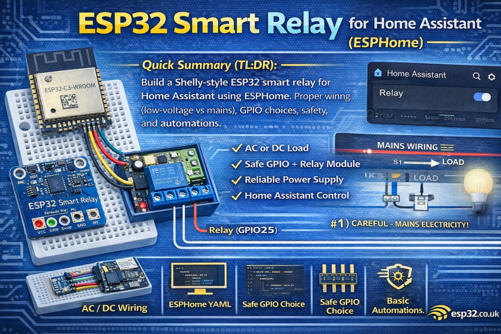
This guide shows how to build a safe ESP32 smart relay (Shelly-style) for Home Assistant using ESPHome (optional MQTT). Includes correct wiring (low-voltage vs mains), relay module selection, GPIO “safe pins”, EMI/noise tips, and example ESPHome YAML for a reliable on/off switch with status, restore mode, and basic automations.
A “Shelly-style” smart relay is basically three things in one box:
- A microcontroller (ESP32)
- A relay (to switch a load)
- A safe power solution (AC→DC or DC supply), plus proper wiring and noise control
This article focuses on making it reliable and safe, not just “it works on a breadboard”.
Mains voltage can kill you and burn your house down.
If you’re not confident working with AC wiring, build the low-voltage version first (12V/24V DC loads), or buy a certified relay device.
1) What you can build (use cases)
A smart relay is perfect for:
- Lights (via contactor/relay depending on load)
- Bathroom fan (with humidity automation)
- Garage door trigger (pulse mode)
- Irrigation valve control (via proper driver/relay)
- Boiler enable input (only if you know the control circuit)
2) Choose your relay hardware (don’t cheap out blindly)
Option A: 1-channel relay module (easy)
For beginners and quick builds:
- Use an opto-isolated relay module designed for microcontrollers.
Look for:
- Proper transistor driver on the board
- Optocoupler (nice-to-have)
- Clear labeling: VCC, GND, IN, COM, NO, NC
Avoid modules that:
- Don’t have a transistor/driver (some super-cheap boards are sketchy)
- Have no diode/snubber considerations for inductive loads
- Have bad isolation distances on the PCB
Option B: “Bare relay + transistor driver” (best practice)
If you want to do it properly:
- Use a relay + NPN transistor or MOSFET driver
- Add flyback diode
- Add snubber/MOV where needed (AC inductive loads)
This is closer to what commercial products do.
3) Powering it (the #1 cause of random resets)
ESP32 hates bad power. Relay coils and mains noise make it worse.
Recommended stable approach
- Power ESP32 from a decent 5V supply (USB charger, buck module, or AC-DC module)
- Then use the ESP32 board’s 3.3V regulator (or a good external 3.3V regulator)
Add capacitors near the ESP32:
- 100 µF electrolytic on 5V rail (or 3.3V rail)
- 0.1 µF ceramic close to the ESP32 VCC/GND
If using mains AC-DC modules (Shelly-style)
Typical AC→DC module choices:
- Encapsulated AC-DC modules (safer than bare capacitive droppers)
- Proper fusing + enclosure + strain relief is mandatory
Again: if you’re not experienced with mains, do the DC version first.
4) Wiring overview
4.1 Low-voltage DC load (recommended first build)
Example: 12V LED strip, DC fan, small DC device.
- 12V+ → Relay COM
- Relay NO → Load +
- Load – → 12V–
- ESP32 powered from a separate stable 5V/3.3V regulator
- Grounds should be common if needed (depends on module), but keep power wiring tidy.
4.2 Mains AC load (danger zone)
For AC wiring you’re switching LIVE typically:
- LIVE → Relay COM
- Relay NO → Load LIVE
- NEUTRAL goes directly to load
- Earth/ground must be continuous where applicable
Do not route mains over breadboards.
Use:
- Proper screw terminals
- Enclosure
- Cable glands
- Fuse
- Adequate isolation/clearance
5) Best ESP32 pins for relay control
Use “safe” GPIO that don’t affect boot:
Good default pins:
- GPIO25, GPIO26, GPIO27, GPIO32, GPIO33, GPIO18, GPIO19, GPIO23
Avoid for relay input (especially if the relay board pulls the pin at boot):
- GPIO0, GPIO2, GPIO12, GPIO15 (boot/strapping pins)
For this guide we’ll use GPIO25.
6) ESPHome YAML (simple, reliable smart relay)
6.1 Minimal config (ESPHome API)
esphome:
  name: esp32-smart-relay
  friendly_name: ESP32 Smart Relayesp32:
  board: esp32dev
  framework:
    type: arduinologger:
api:
ota:wifi:
  ssid: !secret wifi_ssid
  password: !secret wifi_password
  ap:
    ssid: "Relay Fallback"
    password: !secret ap_passwordcaptive_portal:
6.2 Relay switch (GPIO25)
switch:
  - platform: gpio
    name: "Relay"
    pin: GPIO25
    id: relay
    restore_mode: RESTORE_DEFAULT_OFF
restore_mode notes
RESTORE_DEFAULT_OFFis safest (after power outage, relay stays off).- If you need “return to previous state” after outage, use
RESTORE_DEFAULT_ONorRESTORE_INVERTED_DEFAULT_OFFdepending on wiring, but be careful—some loads must not start unexpectedly.
6.3 If your relay module is “active LOW”
Many relay modules turn on when the input is pulled LOW. If yours behaves inverted, add:
switch:
  - platform: gpio
    name: "Relay"
    pin:
      number: GPIO25
      inverted: true
    restore_mode: RESTORE_DEFAULT_OFF
7) Add a physical button (optional but very “Shelly-like”)
Wire a momentary button from GPIO4 → GND.
binary_sensor:
  - platform: gpio
    pin:
      number: GPIO4
      mode: INPUT_PULLUP
      inverted: true
    name: "Wall Button"
    filters:
      - debounce: 30ms
    on_press:
      - switch.toggle: relay
Now the relay can be controlled from:
- Home Assistant
- local physical switch
- automations
8) Safety + reliability upgrades (worth doing)
8.1 Flyback diode (for relay coils if you build your own driver)
If you’re driving a bare relay coil:
- Add a diode across the coil (1N4148/1N4007) to kill voltage spikes.
Most relay modules already include it—verify.
8.2 Snubber or MOV (for AC inductive loads)
For loads like:
- fans
- pumps
- contactors
…use an RC snubber or MOV to reduce arcing and EMI.
This reduces:
- relay contact wear
- ESP32 resets due to EMI spikes
8.3 Separate relay supply (when loads are nasty)
If the relay coil supply is noisy:
- power relay coil from a separate 5V supply
- keep grounds common only if necessary
- route coil currents away from ESP32 ground paths
8.4 Enclosure and strain relief
A “real” Shelly-style build must include:
- insulated enclosure
- strain relief
- fuse (on mains input)
- correct wire gauge
- proper terminals
9) Home Assistant setup ideas (automations)
9.1 Bathroom fan automation (humidity)
- ON when humidity > 70%
- OFF when humidity < 60%
(Add hysteresis so it doesn’t flap.)
9.2 Safety timer (auto-off)
Turn relay off after X minutes:
- Great for heaters, irons, pumps, etc.
9.3 “Pulse mode” (garage door / gate trigger)
If you need a momentary pulse:
switch:
  - platform: gpio
    name: "Gate Trigger"
    pin: GPIO25
    id: relay
    restore_mode: RESTORE_DEFAULT_OFF
    on_turn_on:
      - delay: 300ms
      - switch.turn_off: relay
10) Troubleshooting (common failures)
Relay clicks but ESP32 resets
- Power supply is weak or noisy
- Add bulk capacitance, improve regulator, shorten power wires
- Add snubber/MOV if switching inductive AC loads
Relay is ON at boot
- You used a boot strap pin, or relay input floats
- Move relay control to a safer GPIO (25/26/27/32/33)
- Add proper pull-up/pull-down as needed (carefully)
Home Assistant shows “unavailable”
- Wi-Fi issues or power instability
- Add fallback AP, improve power, check router RSSI