
The PCA9685AliExpress price 16-channel PWM/servoAliExpress price driver is one of the most useful ESP32AliExpress price peripheral boards: it generates 16 independently programmed, 12-bit PWM signals while occupying only two ESP32 bus pins. On the familiar Adafruit-style module, every channel has a three-pin servo connector, plus a dedicated power input and solder pads for changing the I²C address. This guide concentrates on the physical board: pinout, solder jumpers, circuit connections, power supply, PWM timing, and a minimal working Arduino example.
Quick answer: connect ESP32 3V3 to VCC, GND to GND, GPIO21 to SDA, GPIO22 to SCL, and a separate regulated 5–6 V supply to the board’s servo-power V+ and GND terminal. Fit a servo on channel 0 with signal, V+ and ground aligned to the PCB labels. The default PCA9685 I²C address is 0x40.
Safety: VCC and V+ have different jobs. V+ is a power-distribution rail for the servos; it is not the PCA9685 logic supply. Never connect the external 5–6 V servo supply to the ESP32 3V3 pin. Never use a small ESP32 regulator or USB output to supply a bank of servos.
PCA9685 specifications at a glance
| Specification | Value and practical meaning |
|---|---|
| PWM outputs | 16 channels, LED0–LED15, independently adjustable duty cycle/phase |
| PWM resolution | 12 bits per channel: 4,096 counter steps |
| PWM frequency | Common to every output; about 24–1,526 Hz with typical 25 MHz internal oscillator |
| Servo frequency | Usually about 50 Hz; check your specific servo datasheet |
| Control interface | I²C; typically 100 or 400 kHz with ordinary ESP32 wiring (chip supports faster Fast-mode Plus with suitable bus design) |
| Default I²C address | 7-bit 0x40 |
| Address selection | Six chip address bits A0–A5; Adafruit board exposes six solder bridges |
| Logic supply (VCC) | PCA9685 chip operates at 2.3–5.5 V; 3.3 V matches ESP32 logic |
| Servo supply (V+) | Separate power-distribution connection; commonly regulated 5–6 V for hobby servos |
| Output Enable (OE) | Active-low enable: LOW = normal, HIGH = outputs disabled/configured inactive state |
| Output drive | Signal pin is logic-level PWM, not a servo motor power driver |
| One PWM frequency for all | Independent pulse widths, not independent frequencies |
The underlying NXP PCA9685 is marketed as an LED controller, but its adjustable ~50 Hz PWM timing works for many hobby servos. The Adafruit breakout adds 220 Ω series resistors to each signal line, a convenient V+ rail, control-header duplicates for chaining, and a power-terminal arrangement. Those features are board-specific, not universal properties of the IC.
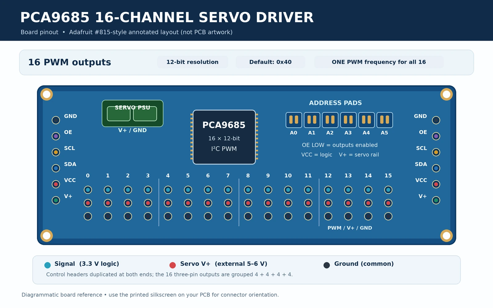
PCA9685 breakout pinout: control, power and 16 servo headers
On the classic Adafruit PCA9685 module, the six-signal control header is duplicated at the two short ends so boards can be chained. Read the PCB silk-screen for orientation; do not interpret the pins purely from an online image that may be rotated. The header names are GND, OE, SCL, SDA, VCC, V+.
| Pin or connector | Function | ESP32 recommendation |
|---|---|---|
| GND | Shared signal ground; common reference for ESP32 and external servo supply | Join ESP32 GND and servo supply negative |
| OE | Active-low Output Enable; pulled low on Adafruit board | Normally leave unconnected; optional GPIO-controlled disable |
| SCL | I²C clock with onboard weak pull-up to VCC | ESP32 GPIO22 (classic example) |
| SDA | I²C data with onboard weak pull-up to VCC | ESP32 GPIO21 (classic example) |
| VCC | Logic power input, not the servo rail | ESP32 3V3 |
| V+ | External positive servo power distribution | Regulated servo supply +5 to +6 V, if servo rating permits |
| Power screw terminal | Feeds V+ and GND; Adafruit design has reverse-polarity protection at this terminal on documented revisions | Use external servo supply; verify your PCB revision |
| CH0–CH15 signal | Independently timed PWM signals at approximately VCC logic levels | Connect to individual servo signal inputs |
| CH0–CH15 V+ | Distribution from external servo supply | Connect to servo red/positive lead |
| CH0–CH15 GND | Common supply ground | Connect to servo brown/black/negative lead |
Each group of three servo header contacts provides signal, V+ and GND. On the classic Adafruit board, the ground-contact row is along the bottom and the signal-contact row along the top in Adafruit’s assembly orientation. Other boards may be mirrored or have differently oriented screw terminals. Verify the S, V+, GND silkscreen or follow the PCB traces before inserting a three-wire connector. Servo lead colours are not perfectly standard.
Why do the servo connectors have three pins?
A typical positional servo requires one PWM signal and two supply wires. The PCA9685 produces the signal, while the power rail distributes current from the external supply. It does not amplify PWM to move a motor by itself: the servo contains its own control electronics and motor driver. A board cannot safely power 16 servos solely because it has 16 headers; voltage regulation, connector capacity, track current and aggregate stall current must all be considered.
Six address solder jumpers: A0–A5 and I²C address selection
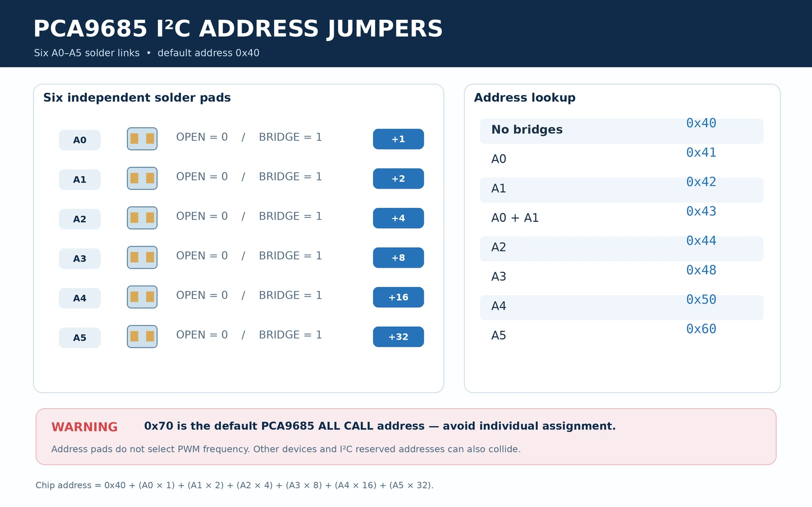
Each PCA9685 has six address inputs. The Adafruit board makes them available as A0, A1, A2, A3, A4 and A5 solder-bridge pads. Unbridged address inputs are low on the Adafruit breakout; bridge a pad to set that address bit high. The ordinary default is 0x40.
| Solder bridges closed | Offset | 7-bit slave address |
|---|---|---|
| None | 0 | 0x40 |
| A0 | 1 | 0x41 |
| A1 | 2 | 0x42 |
| A0 + A1 | 3 | 0x43 |
| A2 | 4 | 0x44 |
| A3 | 8 | 0x48 |
| A4 | 16 | 0x50 |
| A5 | 32 | 0x60 |
| A0 + A2 | 5 | 0x45 |
The address is 0x40 + A0×1 + A1×2 + A2×4 + A3×8 + A4×16 + A5×32, with each A-bit equal to 0 or 1. Although 64 combinations exist mathematically, do not assume every resulting address is appropriate on a mixed I²C bus. NXP identifies the All Call address 0x70 as enabled at power-up, and the range 0x78–0x7F has special I²C uses. Other devices may also occupy possible addresses.
Critical: do not configure a board’s individual address as 0x70. All PCA9685 boards can acknowledge that address as a group, even when they have different hardware addresses. This explains why some I²C scanners show both 0x40 and 0x70 for a single PCA9685. NXP cites up to 62 devices in suitable arrangements; practical mixed-bus designs may support fewer because of collisions and reserved I²C addresses.
Can two PCA9685 boards control 32 servos on one ESP32?
Yes. Give the first board address 0x40 and bridge A0 on the second to select 0x41. Wire both to the same upstream SDA/SCL and common ground; create one Adafruit_PWMServoDriver instance per address. Servo power must be sized for the full set of motors and may be provided via separately rated distribution connections. The I²C chain does not provide extra servo current.
Functional schematic: logic power versus servo power
The primary board-level mistake is connecting the two supplies incorrectly. VCC powers the PCA9685 silicon and determines the signal output high voltage. V+ is routed along the servo power pins and receives power via the board’s supply terminal. Connect the negative side of that supply to GND, which is also the ESP32 ground.
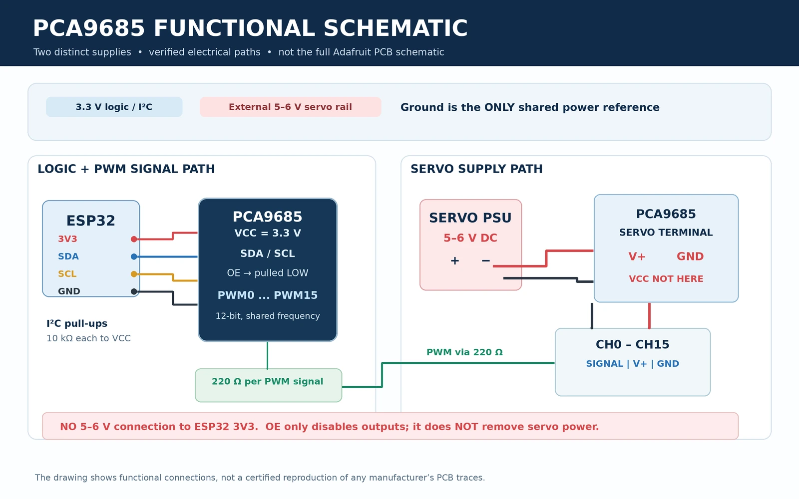
Adafruit’s board uses 10 kΩ pull-ups on SDA and SCL to VCC, so a board powered at 3.3 V can connect directly to the ESP32 I²C bus. If you connect other modules, evaluate the total pull-up network rather than indiscriminately adding more 4.7 kΩ resistors. The Adafruit board pulls OE low by default so all channels are operational without an OE connection.
If controlling OE from an ESP32, wire an ESP32 output to OE and drive HIGH to inhibit outputs; drive LOW to return normal PWM operation. OE is not an emergency-stop device and does not cut servo power. A servo may not stop moving instantly simply because its control pulse disappears. Use appropriately engineered power disconnection and motion safety where needed.
ESP32 wiring diagram: PCA9685 and an external 5 V servo supply
| From | To | Why |
|---|---|---|
| ESP32 3V3 | PCA9685 VCC | 3.3 V silicon power; correct logic level for ESP32 |
| ESP32 GND | PCA9685 GND | Shared communication and PWM reference |
| ESP32 GPIO21 | PCA9685 SDA | I²C data, classic ESP32 DevKit example |
| ESP32 GPIO22 | PCA9685 SCL | I²C clock, classic ESP32 DevKit example |
| External servo PSU +5–6 V | PCA9685 terminal V+ | Servo positive rail; voltage must match servos |
| External servo PSU negative | PCA9685 terminal GND | Completes servo current path; common ground |
| Servo signal | PCA9685 CH0 signal | Pulse signal to first servo |
| Servo positive and ground | PCA9685 CH0 V+ / GND | Independent motor power from PSU |
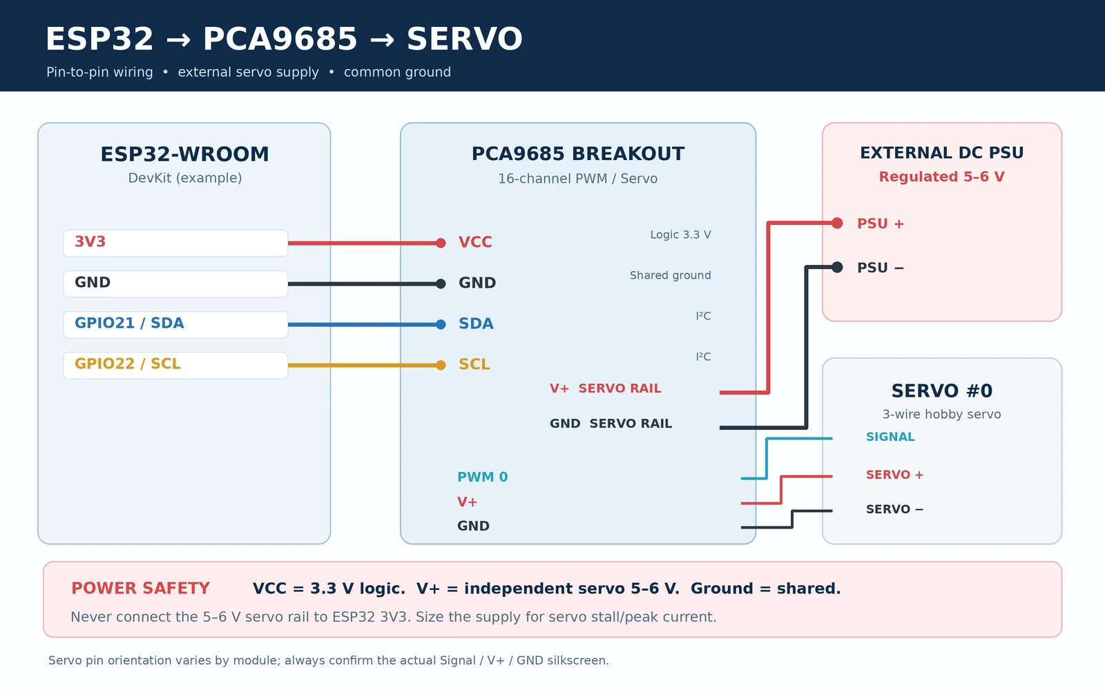
The GPIO21/GPIO22 pairing is appropriate for many classic ESP32-WROOM DevKit boards; ESP32-S3/C3/C6 variants may have different default or suitable I²C pins. The pins in the drawing are an explicit Arduino example rather than a universal ESP32 pinout.
How large should the servo power supply be?
Choose the servo supply according to the motors’ specified stall currents, simultaneous movement, voltage range and duty cycle, not simply 16 multiplied by an arbitrary small current. Even compact servos can draw several hundred milliamps in motion, and larger servos may pull more than an ampere each at heavy load. A 5 V 2 A supply might run a couple of micro servos in a light project but is not a general recommendation for 16 servos.
For supply dips, Adafruit provides a through-hole position for a bulk capacitor on V+. A design starting point is roughly 100 µF per servo, but the correct value depends on load, cable length, power supply impedance and peak current. A low-ESR capacitor with a suitable voltage rating (for example, at least 10 V on a regulated 5–6 V rail) can help with transients; it does not compensate for an undersized supply. Observe electrolytic polarity.
Arduino IDE: official Adafruit PCA9685 library and first servo example
Install Adafruit PWM Servo Driver Library through Arduino IDE Library Manager. Install the prompted dependency Adafruit BusIO if it is not already present. The Adafruit library provides begin(), setPWMFreq(), setPWM() and writeMicroseconds(). Use Wire.begin(SDA, SCL) to select your ESP32 I²C pins before initializing the device.
The following self-contained example uses a modest test sweep around the centre position instead of jumping to unverified mechanical end stops. Set your servo on a stable surface, remove linkages that might hit an obstruction, and verify that its rated supply and control pulse requirements allow the chosen values. The 1,400–1,600 µs range is a cautious example, not a guarantee for every servo.
#include <Arduino.h>
#include <Wire.h>
#include <Adafruit_PWMServoDriver.h>

constexpr int SDA_PIN = 21;        // Classic ESP32 DevKit
constexpr int SCL_PIN = 22;
constexpr uint8_t PCA_ADDR = 0x40;
constexpr uint8_t SERVO_CH = 0;

Adafruit_PWMServoDriver pca(PCA_ADDR);

void setup() {
  Serial.begin(115200);
  delay(400);

  Wire.begin(SDA_PIN, SCL_PIN);
  Wire.setClock(100000);          // Reliable first-test I2C rate

  if (!pca.begin()) {
    Serial.println("PCA9685 not found at 0x40.");
    Serial.println("Check VCC=3.3 V, GND, SDA, SCL and solder pads.");
    while (true) delay(1000);
  }

  // Set the SAME frequency for all 16 channels.
  // Servo manufacturer specifications take precedence.
  pca.setPWMFreq(50);
  delay(10);

  // 1500 microseconds is commonly near servo centre.
  // It is not universally safe for every servo mechanism.
  pca.writeMicroseconds(SERVO_CH, 1500);
  Serial.println("PCA9685 ready; CH0 at 1500 us.");
}

void loop() {
  pca.writeMicroseconds(SERVO_CH, 1400);
  Serial.println("CH0 = 1400 us");
  delay(1500);

  pca.writeMicroseconds(SERVO_CH, 1600);
  Serial.println("CH0 = 1600 us");
  delay(1500);

  pca.writeMicroseconds(SERVO_CH, 1500);
  Serial.println("CH0 = 1500 us");
  delay(1500);
}
These Adafruit API names were checked against the project’s published header and implementation. The code is intended as a working starting point but has not been bench-tested on your particular board or servo. The PCA9685 internal oscillator varies between devices; calibrating the oscillator against measured pulse timing improves accuracy.
How to output simple LED PWM instead
To drive a low-current LED circuit, first remove the servo and ensure the LED is connected with suitable current limiting, polarity and driver circuitry for the selected output mode. All channels run at one common frequency, so switch the frequency to something suitable for LED dimming such as around 1,000 Hz on a separate LED-only board. You cannot use 50 Hz for a servo on CH0 and 1,000 Hz for an LED on CH1 simultaneously on one PCA9685.
// Example after successful pca.begin(), for a separately wired
// low-current LED circuit, not a servo connector:
pca.setPWMFreq(1000);
pca.setPWM(1, 0, 2048);  // About 50% duty on channel 1
// Completely off: pca.setPWM(1, 0, 4096);
// Completely on:  pca.setPWM(1, 4096, 0);
Do not power high-power LEDs or LED strips directly from a PCA9685 signal pin. Use a MOSFET or dedicated current-regulated LED driver suited to the load. Adafruit’s per-signal series resistors are not substitutes for an engineered external LED power circuit.
PWM timing: converting servo microseconds into 12-bit ticks
PCA9685 counts 4,096 positions through each complete PWM cycle. All sixteen channels use the same frequency and therefore the same PWM period; their individual rising and falling positions may differ. At 50 Hz, the period is 20 ms (20,000 µs), so one count represents roughly 20,000 / 4,096 ≈ 4.883 µs. The value is approximate because the internal oscillator is not perfectly accurate.
| Requested servo pulse | Ticks at nominal 50 Hz | Duty within 20 ms |
|---|---|---|
| 1,000 µs | ~205 | 5% |
| 1,400 µs | ~287 | 7% |
| 1,500 µs | ~307 | 7.5% |
| 1,600 µs | ~328 | 8% |
| 2,000 µs | ~410 | 10% |
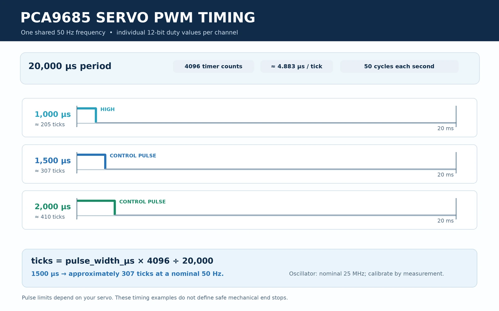
For raw ticks, a conventional pattern is pca.setPWM(channel, 0, offTick), with offTick chosen from 0–4095. For complete OFF use the library’s special 4096 value rather than treating 4095 as identical to 100% off. The official writeMicroseconds(channel, pulse) method saves you from manual conversion, but precision still depends on how accurately the library models the actual oscillator.
How to improve oscillator calibration
Adafruit provides setOscillatorFrequency(hz). The datasheet’s nominal internal oscillator is 25 MHz; the actual clock can vary. To calibrate, connect an oscilloscope or logic analyser to an unloaded PWM signal pin and ground, set a known PWM frequency or pulse width, measure the resulting period, then tune the oscillator-frequency setting to match. Do not assume an example value from someone else’s board is correct for yours.
Common PCA9685 problems and fixes
| Symptom | What to check |
|---|---|
| I²C scanner finds 0x40 but servo does nothing | Check whether V+ has a properly rated servo supply and common ground; VCC alone cannot power servos. |
| ESP32 resets when the servo moves | External supply sag, cable resistance or brownout; do not source servo current through ESP32 3V3/USB. Check peak current and add properly rated decoupling. |
| Servo twitches or buzzes | Incorrect frequency/pulse width, poor supply, common-ground fault, electrical noise or unsuitable linkage load. Start at ~50 Hz and measure. |
| Two boards always move together | They may both be at 0x40; bridge A0 on the second to use 0x41 and create a second software object. |
| Scanner reports 0x70 unexpectedly | The PCA9685 All Call address may be enabled. Do not assign another device to 0x70 by default. |
| Device not detected | Check VCC 3.3 V, GND, SDA/SCL orientation, pull-ups, address bridges and the actual ESP32 model’s chosen GPIOs. |
| Outputs appear disabled | Check OE; on the Adafruit breakout it defaults low, while driving OE high disables the outputs. |
| LED dimming too slow or flickers | PWM frequency is shared; use an appropriate LED-only frequency, not 50 Hz just because the board supports servos. |
| Servos reach mechanical stop | Uncalibrated endpoint pulses or mismatched servo. Reduce pulse range and verify its allowed mechanical travel. |
PCA9685 compared with ESP32 LEDC, MCP23017 and TLC5940
ESP32 hardware LEDC PWM is often sufficient for a small number of outputs and needs no extra breakout. A PCA9685 is attractive when many PWM signals are required, when you want 12-bit channel timing over two I²C pins or when you want a dedicated servo header board. A MCP23017 increases digital GPIO count but does not replace a 16-channel hardware PWM device. LED-current-driver ICs may be a better fit for high-current lighting than a servo-oriented PCA9685 module.
For home automation rather than Arduino sketches, your existing PCA9685 ESP32/ESPHome guide covers the software configuration. This hardware reference focuses on power distribution, physical jumpers, PWM electrical behavior and the standalone Arduino example.
Frequently asked questions
Can the PCA9685 drive 16 servos at once?
Yes, there are 16 independent signal outputs. Whether all sixteen servos can move under load simultaneously depends on the external power supply, current distribution and the servos’ stall and motion demands—not the presence of 16 output headers.
Does PCA9685 work with a 3.3 V ESP32?
Yes. Supply the PCA9685 breakout’s logic VCC at 3.3 V and use 3.3 V-compatible I²C. Servo V+ can be supplied separately at its rated operating voltage. Check whether your particular servo reliably accepts a 3.3 V logic-high control signal.
Can it use I²C address 0x70?
Do not use 0x70 as an individual board address on a default PCA9685 bus. The address is configured as an All Call group address and may be acknowledged by multiple boards.
Is OE an emergency-stop input?
No. OE disables/configures signal outputs as selected by the chip registers, but does not disconnect V+ or guarantee physical motor braking. Treat mechanical safety independently.
Can I run LEDs at 1 kHz and servos at 50 Hz on different PCA9685 channels?
No. All 16 channels share one PWM frequency. Use a separate driver or a different MCU PWM peripheral when two distinct frequencies are needed.
Sources and board-revision notes
- Adafruit PCA9685 breakout pinouts — VCC versus V+, OE, channel connectors and output resistors.
- Adafruit address solder-jumper guide — A0–A5 and chaining multiple boards.
- Adafruit hookup and servo-power guidance — separated supplies, brownouts and capacitors.
- NXP PCA9685 product technical reference — 12-bit 16-channel engine, supply and frequency specifications.
- Official Adafruit PWM Servo Driver Arduino library — software API and examples.
Scope and accuracy: This article uses the classic Adafruit #815-style breakout as its primary reference and distinguishes it from generic PCA9685 16-channel blue boards. Header locations, reverse-polarity protection, capacitor footprints and jumper artwork can differ by manufacturer and revision. Never reproduce PCB traces or power ratings from a drawing that has not been verified against the exact board.