
In this esp32.co.uk/ article, we examine the PCF8523 breakout pinout, backup-cell operation, accurate ESP32 connection tables and the Adafruit RTClib setup.
The PCF8523 real-time clock (RTC) gives an ESP32 a battery-backed calendar and seconds counter that continue running after the microcontroller loses power. It uses a 32.768 kHz external quartz crystal, communicates over I²C, and offers an alarm, countdown timers, a configurable clock output and software drift compensation. This hardware-reference guide covers the Adafruit PCF8523 STEMMA QT breakout #5189, the older header-only Adafruit #3295, the underlying chip pinout, an ESP32 pin-to-pin connection table and a complete Arduino IDE example using Adafruit RTClib.
Quick answer: connect 3V3 → VCC/VIN, GND → GND, GPIO21 → SDA and GPIO22 → SCL on a classic ESP32-WROOM DevKit, matching the labels printed on your breakout. The clock uses the fixed 7-bit I²C address 0x68; there are no address-selection solderPriceAliExpress price jumpers. Fit the specified CR1220 backup battery if you need timekeeping after the main supply is removed.
Important: the PCF8523 and DS3231PriceAliExpress price both use 0x68, so two such clocks cannot be independently addressed on one ordinary I²C segment. The PCF8523 is also not a temperature-compensated clock: for better long-term absolute accuracy the DS3231 is typically the stronger choice.
PCF8523 specifications: what does this RTC actually provide?
| Feature | Specification / consequence |
|---|---|
| Clock and calendar | Seconds, minutes, hours, weekdays, days, months and years |
| Bus | I²C; default/fixed 7-bit address 0x68; silicon supports up to 1 MHz Fast-mode Plus with suitable bus hardware |
| Crystal | External 32.768 kHz tuning-fork quartz; board supplies this component |
| Accuracy | Not temperature-compensated. Adafruit warns of gains/losses up to roughly 2 seconds/day in typical use; calibration can correct measured rate error |
| Power supplyPrice | PCF8523 silicon operates across a wide range; Adafruit breakout can be used at 3.3 V or 5 V logic but match your microcontroller logic |
| Backup battery | Separate VBAT input; Adafruit carrier accepts non-rechargeable CR1220 coin cell for backup |
| Backup consumption | Very low power for RTC-only operation; chip typical backup current is about 150 nA under specified conditions |
| Extra output | SQW / INT1-CLKOUT pin for square wave or interrupt, subject to mode selection |
| Timers and alarm | Calendar alarm plus timer interrupts; useful for low-power data loggers |
| Offset correction | Signed -64…+63 trim register, with correction modes every 2 hours or every minute |
| Stock/lifecycle | NXP currently lists the PCF8523 as no longer manufactured; Adafruit still lists breakout products |
NXP’s product-status listing refers to the chip’s manufacturing status. It does not mean all breakout-board stock has disappeared, but it matters if designing something that must be built and serviced over several years. Verify component availability and consider an actively manufactured RTC before committing to a production PCB.
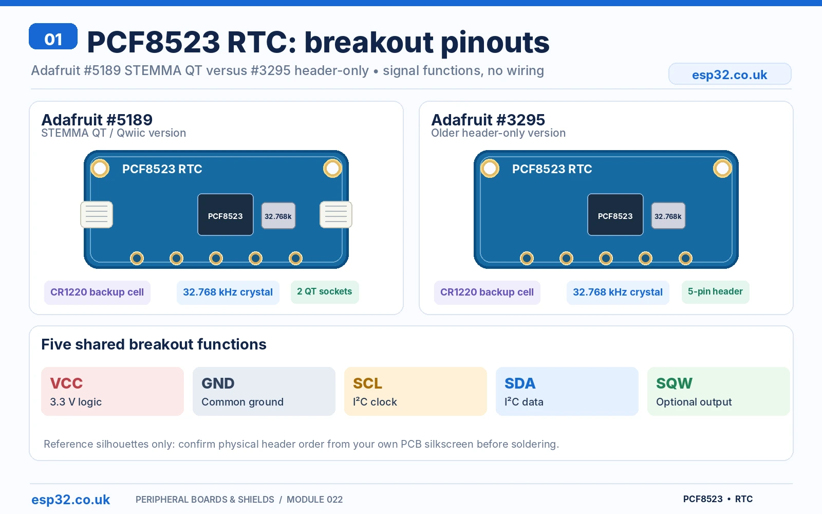
Adafruit PCF8523 breakout pinout: VCC, GND, SDA, SCL and SQW
Adafruit’s #5189 includes two STEMMA QT / Qwiic connectors, a battery holder and a five-signal through-hole header. The older #3295 is a header-only breakout; its PCB revision may contain an SOIC-8 or HVSON-8 PCF8523. Both have the same functional signals, but the physical left-to-right header order can differ by board side, rotation and revision. Use the actual printed silkscreen as your reference rather than the position of an unverified picture.
| Printed breakout signal | Meaning | ESP32 use |
|---|---|---|
| VCC (sometimes VIN on artwork) | Main clock supply and pull-up logic reference; this Adafruit breakout has no regulator that makes its I²C pins automatically independent of VCC | Power from ESP32 3V3 |
| GND | Common reference | ESP32 GND |
| SDA | I²C bidirectional data | Classic ESP32 GPIO21 |
| SCL | I²C clock | Classic ESP32 GPIO22 |
| SQW | Clock output / interrupt functionality when enabled; open-drain signalling | Optional GPIO input with appropriate 3.3 V pull-up |
| STEMMA QT pair | Parallel four-wire bus connectors carrying VCC, GND, SDA and SCL | Alternate connection on #5189; not a second independent RTC bus |
| CR1220 holder | Backup supply for timekeeping | Not a power bank for the ESP32 |
The Adafruit design has I²C pull-ups of approximately 10 kΩ to VCC. Running the module from 5 V while directly attaching an unprotected 3.3 V ESP32 would place inappropriate high-voltage levels on the bus. Use 3.3 V for ESP32 wiring. Check other modules on the same bus before adding more pull-up resistors.
PCF8523 chip pinout is not the same as the breakout header
The PCF8523 is sold in several packages. The 8-pin SOIC chip has oscillator pads, a separate main supply and backup supply, a ground pin, I²C data and clock and a multifunction output. You cannot wire a bare PCF8523 in the same way as a labelled Adafruit module without also supplying its quartz crystal and required passive components.
PCF8523 address and I²C scanner results
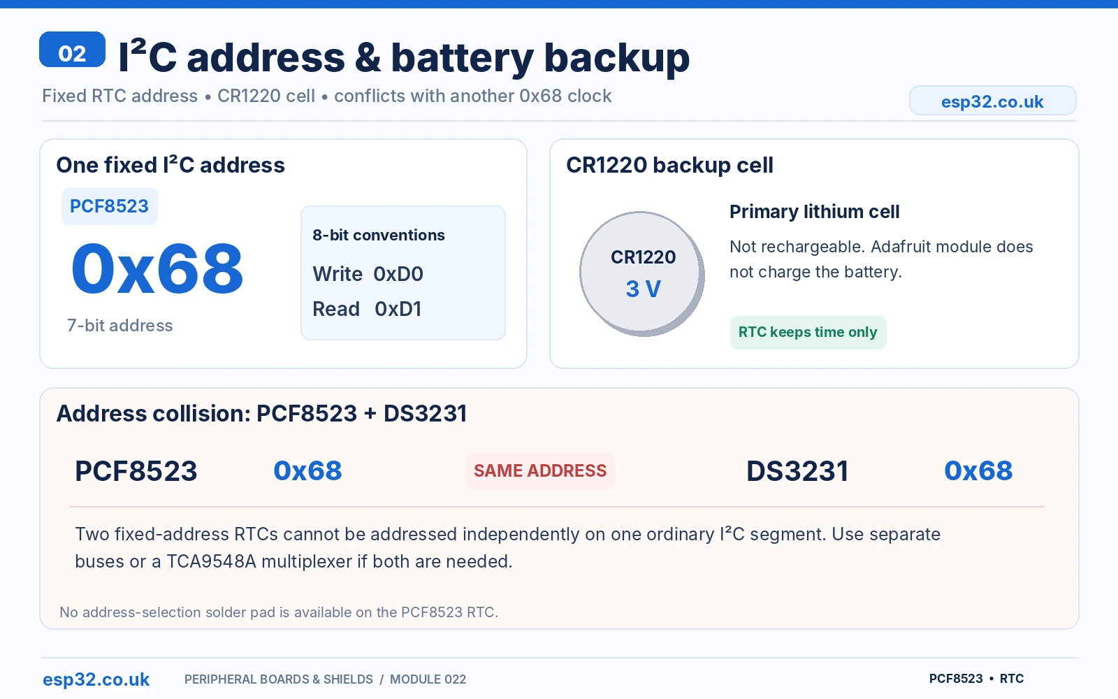
The normal seven-bit address is 0x68, which is fixed for the off-the-shelf PCF8523. A datasheet may quote 0xD0 for an 8-bit write address and 0xD1 for read. Arduino Wire, RTClib and an I²C scanner use the seven-bit value 0x68 instead.
There is no equivalent of the A0/A1/A2 address solder bridges found on a PCF8574AliExpress price or MCP23017. If you need two fixed-address RTCs, put them on separate microcontroller I²C controllers or separate branches of an I²C multiplexer. A TCA9548A multiplexer is one supported method, although an ordinary logger almost never needs two RTCs.
CR1220 backup battery: what happens when ESP32 power is removed?
The Adafruit breakout contains a dedicated CR1220 holder. The primary 3 V lithium cell supplies the PCF8523 VBAT input when normal VCC falls below the switchover condition and the RTC is configured correctly. CR1220 is not rechargeable. The Adafruit breakout does not function as a coin-cell charger. Do not replace it with an arbitrary rechargeable chemistry, put it in backwards, or connect the coin-cell terminal as an ESP32 power supply.
A correctly configured RTC should keep counting on the backup cell, while the ESP32 itself shuts down when its supply is removed. Once power returns, the ESP32 reads the clock over I²C and obtains the elapsed time. The clock does not store time-zone rules or automatically synchronise itself over the internet.
Battery switchover setting and first-start behaviour
In Adafruit RTClib, adjust() not only sets time but also configures the PCF8523 battery switchover mode. Check initialized() and lostPower() when first bringing up a board. The oscillator-stop indicator can remain asserted briefly after initial power because the crystal requires time to stabilise; allow approximately two seconds on a fresh board before drawing conclusions from it.
Do not set the RTC on every boot. Doing so would overwrite its accurate battery-backed time with the sketch build time each time the ESP32 reboots. Use a conditional first-time adjustment or a deliberate manual/NTP synchronisation action.
Bare PCF8523 SOIC-8 chip pinout and functional reference
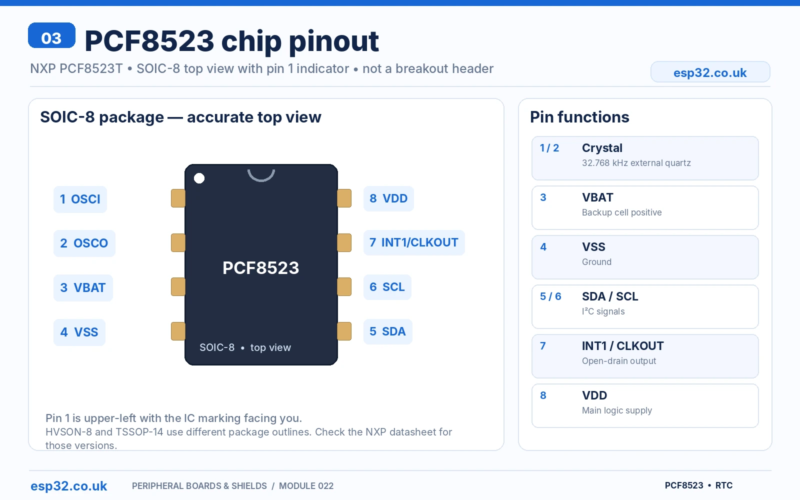
NXP’s datasheet specifies the following SO8 top view. The pin-1 indicator appears at the upper left: pins 1–4 descend along the left edge; pins 8–5 descend along the right. This is not the same as looking at the solder side of a breakout PCB.
| Chip pin | Signal | Purpose |
|---|---|---|
| 1 | OSCI | 32.768 kHz crystal input; high-impedance oscillator net |
| 2 | OSCO | 32.768 kHz crystal output; keep layout very short |
| 3 | VBAT | Separate battery backup input |
| 4 | VSS | Ground reference |
| 5 | SDA | I²C data input/output |
| 6 | SCL | I²C clock input |
| 7 | INT1/CLKOUT | Open-drain interrupt or configurable clock output |
| 8 | VDD | Main power supply |
For a custom board, the quartz oscillator pins require a carefully designed, low-noise layout with the crystal and its specified load configuration; the supply requires adequate decoupling and the I²C lines require pull-ups chosen for bus capacitance and operating speed. An Adafruit breakout already provides those elements. The chip-level reference is not a full manufacturing schematic.
ESP32-to-PCF8523 connections: wire-free lookup table
| Classic ESP32-WROOM DevKit | Adafruit PCF8523 | Function |
|---|---|---|
| 3V3 | VCC / VIN, follow PCB marking | 3.3 V main logic supply |
| GND | GND | Shared ground |
| GPIO21 | SDA | I²C data |
| GPIO22 | SCL | I²C clock |
| Optional GPIO25 input | SQW | Optional status/clock interrupt with verified pull-up to 3.3 V |
| No ESP32 connection | Coin-cell holder | Backup supply to PCF8523 |
| No additional connection needed | Second STEMMA QT socket | Optional chaining connector, not necessary |
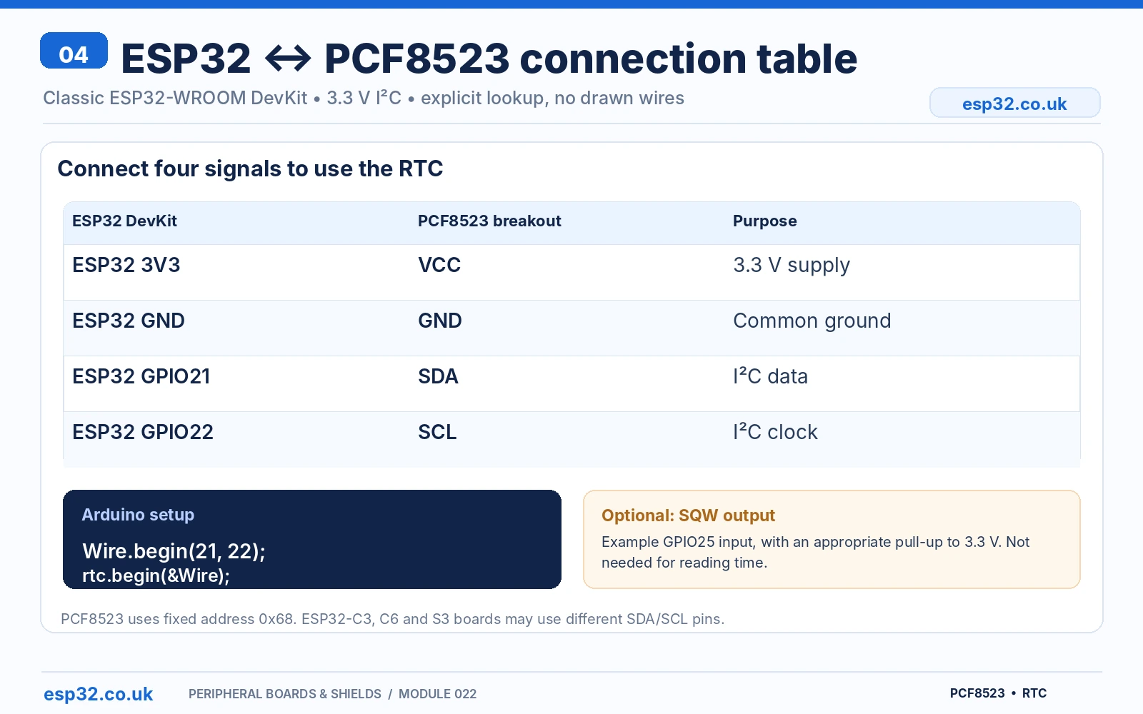
Unlike a custom raw chip circuit, the breakout is designed for straightforward I²C use. A simple first test needs only four signal/power connections. Keep the I²C clock at 100 kHz until the bus is working; higher speeds require short wiring and compatible pull-ups. If an ESP32-C3, C6, S3 or another board is used, change the SDA and SCL GPIOs in the code to its actual safe pinout.
Arduino IDE: working Adafruit RTClib example
Install RTClib by Adafruit from the Arduino IDE Library Manager and any dependency suggested by the IDE (such as Adafruit BusIO). Select the correct ESP32 development board and open Serial Monitor at 115200 baud. This example initialises the I²C interface, checks the clock, sets compile time only when it appears uninitialised or to have stopped, then reads current time once a second.
#include <Arduino.h>
#include <Wire.h>
#include <RTClib.h>

constexpr int I2C_SDA = 21;  // Classic ESP32-WROOM DevKit
constexpr int I2C_SCL = 22;
RTC_PCF8523 rtc;

void setup() {
  Serial.begin(115200);
  delay(400);
  Wire.begin(I2C_SDA, I2C_SCL);
  Wire.setClock(100000);

  if (!rtc.begin(&Wire)) {
    Serial.println("PCF8523 not detected at I2C 0x68");
    Serial.println("Check VCC=3.3V, GND, SDA and SCL.");
    while (true) delay(1000);
  }

  // Crystal start-up may require ~2 s on a new board.
  delay(2000);

  if (!rtc.initialized() || rtc.lostPower()) {
    Serial.println("Clock needs time setting.");
    // Uses build computer's time, NOT actual live UTC.
    rtc.adjust(DateTime(F(__DATE__), F(__TIME__)));
  }

  rtc.start();
  Serial.println("PCF8523 ready.");
}

void loop() {
  DateTime t = rtc.now();

  Serial.printf("%04u-%02u-%02u %02u:%02u:%02u\n",
                (unsigned)t.year(), (unsigned)t.month(),
                (unsigned)t.day(), (unsigned)t.hour(),
                (unsigned)t.minute(), (unsigned)t.second());

  delay(1000);
}
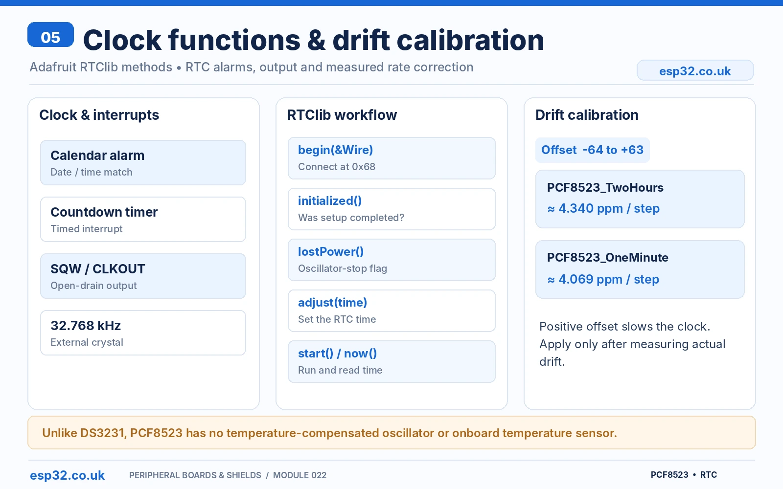
This sketch uses RTClib methods begin(&Wire), initialized(), lostPower(), adjust(), start() and now(), as defined in the official library API. It has not been physically bench-tested here. The initial compile-time setting is only a convenience for a first test, and could be minutes or hours behind real time after a delayed upload. For an internet-connected product, use ESP32 NTP to set an explicit UTC time instead.
Example Serial Monitor output
PCF8523 ready.
2026-11-04 12:00:01
2026-11-04 12:00:02
2026-11-04 12:00:03
The output above is illustrative and not a live measurement. The PCF8523 holds calendar fields but not a time-zone or daylight-saving definition. UTC timestamps are usually easier for sensor data logging; convert for display rather than silently changing the RTC itself twice per year.
Square-wave output, alarms and countdown timers
The PCF8523 supports a programmable clock output (SQW) and interrupt-related functions. The Adafruit breakout brings out a single SQW pin rather than every possible package output. On the SO8 version, its shared signal is INT1/CLKOUT; some other chip packages expose additional functions, which must not be mistaken for extra header pins on the breakout.
The square-wave frequencies supported by Adafruit’s current RTClib enum include 1 Hz, 32 Hz, and approximately 1, 4, 8, 16 and 32 kHz. The manufacturer also provides a calendar alarm and programmable timers. Keep the output open-drain nature in mind: if you read SQW with an ESP32 input, it needs an appropriate pull-up to the ESP32’s 3.3 V logic level.
// Optional, after rtc.begin() and time initialisation:
// rtc.writeSqwPinMode(PCF8523_SquareWave1HZ);
// Use a 3.3V-pulled-up input to read the SQW output.
// rtc.writeSqwPinMode(PCF8523_OFF); // disable
PCF8523 drift calibration: when and how to use it
The PCF8523 is not temperature compensated like the DS3231, but it does have a signed correction register that can be used to reduce measured frequency error. The available range is -64 to +63 calibration steps. Adafruit’s RTClib offers calibrate(PCF8523_TwoHours, offset) and calibrate(PCF8523_OneMinute, offset). The first mode changes the rate by approximately 4.340 ppm per step; the second uses about 4.069 ppm per step.
A +1 offset makes the clock slower; -1 makes it faster. Do not tune it at random. First compare the module against a trustworthy time source over several days, calculate its observed rate error, and then apply a small correction, testing again. Crystal drift from changing ambient temperature cannot be perfectly eliminated by a single fixed offset.
| Error / task | Recommended action |
|---|---|
| Clock gains 1–2 seconds each day | Measure the error rate over several days; consider an appropriate small positive calibration offset |
| Clock loses 1–2 seconds each day | Measure first, then consider an appropriate small negative offset |
| Square-wave output seems stuck | Check RTClib SQW mode, relevant output-enable settings, and the required 3.3 V pull-up |
| Need a wake-up event | Use the PCF8523 alarm/timer and an ESP32 wake-capable GPIO appropriate to your model |
| Need high clock accuracy without calibration | Consider DS3231, which has an integrated temperature-compensated oscillator |
PCF8523 versus DS3231: which RTC should you choose?
| Characteristic | PCF8523 | DS3231 |
|---|---|---|
| Clock architecture | External 32.768 kHz crystal, no active temperature compensation | Integrated temperature-compensated oscillator |
| Typical practical accuracy | Can drift about 1–2 seconds/day; calibratable | Typically far better: specified ±2 ppm over 0–40 °C for common version |
| I²C address | Fixed 0x68 | Fixed 0x68 |
| Battery backup | Built-in switchover, very low backup power | Built-in backup, accurate power-off clock |
| Special features | Alarms, timers, square-wave, drift offset | Two alarms, square-wave, temperature reading, aging offset |
| Good fit | Simple low-power clocks, educational hardware, calibration experiments | Offline timestamps when higher accuracy matters |
Your site already covers ESP32 I²C troubleshooting in the I²C scanner guide. Once the DS3231 breakout-reference draft is published, it can also be internally linked here to form a tight two-article RTC cluster.
PCF8523 common problems
| Symptom | Check |
|---|---|
| No device at 0x68 | VCC 3.3 V, GND, SDA/SCL labels, ESP32 pin mapping, power wiring, and the installed I²C pull-ups |
| Scanner finds 0x68 but time looks wrong | Clock may never have been set or has stopped; check initialized() and lostPower() |
| Time resets when power removed | CR1220 missing, exhausted, reversed or poor contact; battery switchover not configured |
| Time differs after a sketch upload | Compile timestamp was not live time; set RTC by NTP/UTC or manual trustworthy time |
| Clock loses time regularly | Quartz tolerance and temperature drift; check RTC offset calibration and crystal integrity |
| Cannot communicate with DS3231 as well | Both devices have 0x68; put them on separate I²C buses or multiplexer channels |
| SQW not changing state | Confirm chosen SQW mode and open-drain pull-up to 3.3 V |
| Board gets hot / ESP32 misbehaves | Wrong supply, shorts, or 5 V I²C pull-ups applied to ESP32 GPIO. Disconnect and inspect before reuse |
Frequently asked questions
Is the PCF8523 I²C address 0x68 or 0xD0?
Both represent the same slave in different conventions: 0x68 is the seven-bit address used by Arduino; 0xD0 is an eight-bit write address. Use 0x68 in code.
Does PCF8523 have an address jumper?
No. The normal PCF8523 address is fixed at 0x68. A solder pad on an unfamiliar generic module should not be assumed to be an address selector.
Does it charge its CR1220 battery?
No. The Adafruit PCF8523 backup holder is intended for a non-rechargeable CR1220, and the breakout is not a battery charger. Follow Adafruit’s product instructions and do not confuse it with charging circuits found on some unrelated DS3231 modules.
Can the PCF8523 and DS3231 share SDA and SCL?
Not directly on the same bus segment if independent access is needed, because both answer at 0x68. Separate buses or a multiplexer can isolate them.
Is the PCF8523 still being manufactured?
NXP’s current product page marks the PCF8523 as no longer manufactured. Finished Adafruit breakouts may remain in stock, but check availability before selecting the chip for a new long-life design.
Technical references
- NXP PCF8523 original datasheet — SOIC-8 pinout, oscillator, battery backup, I²C register and alarm information.
- NXP PCF8523 lifecycle page — currently marks the chip no longer manufactured.
- Adafruit PCF8523 board pinouts — VCC, GND, SCL, SDA, SQW and STEMMA QT.
- Adafruit #5189 product page — CR1220 holder and STEMMA QT revision.
- Adafruit #3295 original product — older header-only board and PCB-revision notes.
- Adafruit RTClib PCF8523 class API — initialisation, time and calibration methods.
Editorial verification: All electrical connections are provided as checked pinout tables with no drawn wires; do not substitute the generic module’s physical pad order for Adafruit’s. The example uses an ordinary ESP32-WROOM DevKit and the published RTClib API, but has not been physically bench-tested.