A battery-powered logger can spend a few milliseconds taking a reading and several seconds waiting for the next one. If the STM32PriceAliExpress price spends that whole interval in a busy loop, reducing the sample rate saves much less energy than you might expect. On the STM32F103 Blue PillPriceAliExpress price, Sleep, Stop and Standby give you three ways to make the waiting interval cheaper. They differ in the clocks that run, the state they preserve and where your code starts after wake-up.
In this esp32PriceAliExpress price.co.uk/ guide, you will use one pushbutton on PA0 and a serial terminal to exercise all three modes. Sleep and Stop should return to the code that requested the mode. Standby should produce a new boot message with the Standby flag set. Once you can tell those outcomes apart, you will measure the current of your actual board and estimate the average current of a periodic sampling job.
The example targets an STM32F103C8T6 and uses STM32CubeF1 HAL. It keeps the internal 8 MHz HSI as the system clock so the first experiment works with the clock that the STM32 selects on Stop exit. You can then extend the same application to a faster clock configuration, with an explicit restoration step after wake-up.
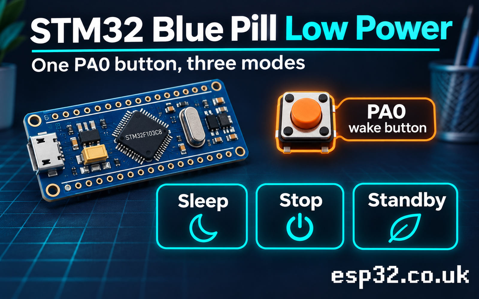
What Sleep, Stop and Standby preserve
Sleep stops instruction execution in the Cortex-M3 core. The peripheral clocks that you configured can continue to run, so an interrupt from a clocked peripheral can wake the processor. Your stack and local variables are still there when the call returns. This fits a programme that needs to keep servicing a peripheral and has short gaps between events. The current depends in part on which clocks and peripherals you leave running.
Stop keeps SRAM and the relevant register state while halting the high-speed oscillators and clocks in the core domain. For this WFI lab, an interrupt on a configured EXTI line wakes the processor. The system clock on exit is HSI. If the programme used a faster PLL clock before entering Stop, code can resume at an instruction that assumes the old clock even though the clock tree has changed. This is why an ordinary UART or timer can behave differently immediately after Stop. ST RM0008, low-power modes and clock control
Standby switches off the internal regulator that supplies the main core domain. Normal SRAM and most register state are lost. When an enabled wake source fires, the MCU starts through the reset path. The backup domain can preserve its own state while supplied. For example, the LSE-driven clock and backup register marker in the STM32 RTC tutorial can provide a timestamp across successive runs. A variable kept on the application stack cannot play the same role.
| Mode | What happens to the core and clocks | PA0 wake path in this lab | What the terminal should show |
|---|---|---|---|
| Sleep | Core sleeps. Enabled peripheral clocks can continue. | Rising edge through EXTI0 and its NVIC interrupt | Code returns after the mode call |
| Stop | Main high-speed oscillators and core-domain clocks stop. SRAM is retained. | Rising edge through EXTI0 and its NVIC interrupt | Code returns with HSI selected |
| Standby | Main internal regulator switches off. Normal SRAM is lost. | Rising edge on the enabled PA0 WKUP pin | Programme boots again. Inspect SBF and WUF. |
The same external pin can participate in two different paths. EXTI0 and its IRQ are used by the Sleep and Stop example. The PWR wake pin is armed separately for Standby. Other Standby exits include an RTC alarm, an IWDG reset or an external reset on NRST. A wake pin and a normal GPIO interrupt can share the physical signal without sharing all their configuration. ST STM32F103x8/xB datasheet
Think about what the outside circuit sees while the processor is away. In Stop, the F103 keeps its I/O state, so an output controlling a peripheral can remain asserted throughout the wait. That is useful for holding a chip select inactive. It can also keep an external load powered for much longer than intended. In Standby, most I/O pins become high impedance. For a signal that needs a defined level while the MCU is unavailable, inspect the external pull network or the peripheral’s own default state. Make that choice per pin, especially for regulator enables and bus lines that connect to independently powered devices.
The Stop regulator selection is another trade-off within the same mode. Keeping the main regulator in its normal state reduces the recovery delay. Selecting its low-power state reduces idle consumption at the cost of extra recovery time. Both variants retain SRAM. For a latency-sensitive design, measure from the electrical wake edge to the first meaningful application action. That measurement includes the regulator and clock transition, interrupt handling, and any software setup. A clean interrupt edge does not by itself tell you when the sensor is ready. ST RM0008, Stop mode entry and exit
Wire the wake button and serial terminal
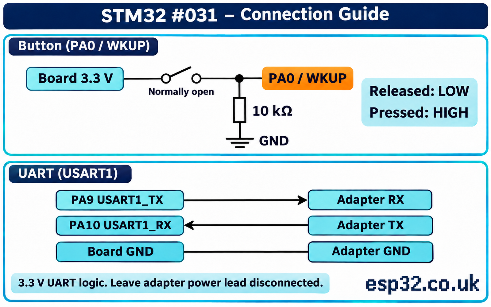
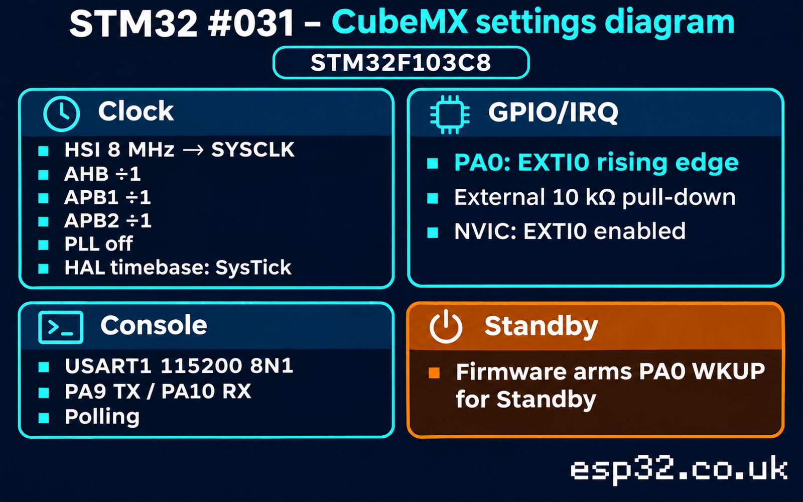
Start with the board powered by one documented source. Use a normally open pushbutton between PA0 and the board’s 3.3 V rail, and put a 10 kΩ pull-down between PA0 and GND. This makes the released level low and gives you a rising edge on press. The resistor keeps the idle level defined independently of the ordinary GPIO configuration, which matters when entering Standby. Check the physical PA0 label on your board before wiring.
| From | To | Function |
|---|---|---|
| Board 3.3 V | One side of normally open button | Logic high when pressed |
| Other side of button | PA0 | EXTI0 input and dedicated WKUP pin |
| PA0 | 10 kΩ resistor to board GND | Released idle level is low |
| PA9 USART1_TX | USB-UART adapter RX | Read the terminal messages |
| PA10 USART1_RX | USB-UART adapter TX | Send commands |
| Board GND | Adapter GND | Common signal reference |
Use a UART adapter with 3.3 V logic and leave its power output disconnected when the board has its own supply. UART TTL-level signals connect TX to RX and RX to TX. RS-232 voltages and a 5 V adapter output are unsuitable for this setup. For the button, confirm that pressing it connects PA0 to the 3.3 V rail through the switch, rather than connecting the supply directly to ground through the contacts. A four-leg tactile switch often has two internally joined pairs, so a continuity check can save time.
Keep the button released when you request a mode. When you want to wake the MCU, press and release it once. Mechanical bounce may generate several rising edges, so the interrupt counter in the example is an observation of edges. If you need one application action per press, use the debouncing policy from the STM32 EXTI button tutorial. For this exercise the first usable edge is enough to resume or reboot.
Configure CubeMX for an HSI baseline
Create a project for STM32F103C8Tx with Serial Wire debugging and USART1 asynchronous at 115200 baud, eight data bits, no parity and one stop bit. Keep default USART1 pin mapping, PA9 for TX and PA10 for RX. Open a matching serial terminal. Before adding low-power code, verify that the first boot message appears and that sending a character reaches the receive call. This separates serial wiring and baud errors from power-mode problems. The CubeMX project setup guide and STM32 UART tutorial cover the surrounding setup.
In the Clock Configuration view choose HSI directly as SYSCLK, with AHB and APB dividers of one. HCLK and both peripheral clocks are then nominally 8 MHz. Leave PLL off for this experiment. Use SysTick as the HAL timebase. If your project uses a hardware timer as its timebase, the SysTick pending-bit cleanup in this example will not manage that timer’s interrupt. Start with a fresh lab project so you can account for every enabled interrupt and clock.
Set PA0 to GPIO_EXTI0, configure a rising-edge interrupt and choose no internal pull because the board has the external resistor. Enable the EXTI line 0 interrupt in NVIC. Check that the generated EXTI0_IRQHandler() calls HAL_GPIO_EXTI_IRQHandler(GPIO_PIN_0). Leave the WKUP selection to the runtime code. Leave USART interrupt and DMA disabled for this polling-based terminal example. The code enables the PWR peripheral clock and uses the HAL PWR functions, so include the PWR module in the generated build.
The F103 peripheral naming differs from other STM32 lines. The single wake pin for this lab is PWR_WAKEUP_PIN1 in the F1 HAL. There is no need to search the CubeMX menus for a later-family Stop 2 setting. The sample uses PWR_LOWPOWERREGULATOR_ON for Stop and the standard Standby call for the lowest-power mode discussed here. ST STM32F1 HAL power driver
Handle the last interrupt before sleep
If you simply place HAL_PWR_EnterSTOPMode() after a pin check, a button edge can occur between the check and the WFI instruction. The interrupt handler can run and consume the event, and then the processor can enter Stop even though the user just pressed the button. The lab uses a short PRIMASK critical section around the final check and entry. It checks the software edge count, the current pin level and the peripheral pending flag. With normal NVIC configuration and no other priority masking, an eligible IRQ that becomes pending while masked by PRIMASK can terminate WFI. Its handler runs once the foreground unmasks interrupts. ST PM0056, Cortex-M3 programming manual
The critical section also suspends the HAL SysTick interrupt and clears an already pending SysTick request. This avoids an immediate return caused by the periodic tick. The code restores the tick and interrupt handling when the call returns or the attempt is skipped. It leaves EXTI pending state to the normal HAL IRQ handler. Clearing EXTI0 unconditionally just before WFI could throw away the wake edge you intended to observe.
RM0008 lists other pending conditions that can prevent Stop entry, including pending EXTI and peripheral interrupts and the RTC alarm flag. The lab assumes a fresh application with no configured RTC alarm or other interrupt sources beyond the tick and PA0. If you bring the example into the RTC project, confirm the alarm is disarmed or service its pending state according to your wake policy. A pending flag may be an event the application still owes work for. Have its owner acknowledge it, rather than putting a broad register clear into the sleep function. ST RM0008, Stop mode entry conditions
Suspending the tick also means that HAL_GetTick() cannot tell you how long the board spent asleep. The counter counts served tick interrupts. For example, if the user waits 20 seconds before pressing PA0, the difference between HAL tick values around the call can be close to zero. Use the RTC or an external time reference when the elapsed interval matters. In a scheduler, decide how to reconcile expired timers after wake. A sensor deadline based on seconds of real time needs a source that continues advancing for the chosen power mode.
For Standby, prepare the dedicated wake pin with PA0 low. Disable the wake pin, clear the old wake flag, then enable the pin. The F103 can latch a wake event when the pin is already high at enable time. The code checks again after arming and abandons that attempt if the button is high or a wake flag is already present. A transition right at entry can produce an immediate return or a very short Standby followed by reboot. Check the UART message and power trace to tell those cases apart. In a field design, it is often acceptable for a near-simultaneous event to defer sleep or wake the processor immediately.
The foreground routine expects ordinary privileged thread mode with interrupts initially enabled. The lab has no RTOS scheduler, and SysTick is the HAL timebase. A scheduler needs to own tick suppression and coordinate runnable tasks. If you adapt the example, the broader question is whether any code can submit work just before the idle decision. Handle that contract before trying to reduce the number of instructions in the entry path.
Add the low-power lab code
The package includes lp_lab.h, lp_lab.c and the main.c insertion snippets. Copy the header into the generated include directory and the C file into the source directory. The Lp_ReadBoot() call samples PWR and RCC status before this lab clears the two PWR status flags. In the default generated project, call it after HAL_Init() and before code that might clear those flags. If you have an existing project with startup hooks, find where they reset flags first.
/* file: lp_lab.h */
#ifndef LP_LAB_H
#define LP_LAB_H

#include <stdint.h>

typedef enum { LP_SLEEP, LP_STOP, LP_STANDBY } LpMode;
typedef enum { LP_RETURNED, LP_STANDBY_RETURNED, LP_BUTTON_BUSY, LP_BAD_CONTEXT } LpResult;

typedef struct {
    uint32_t pwr_csr;
    uint32_t rcc_csr;
} LpBootFlags;

LpBootFlags Lp_ReadBoot(void);
LpResult Lp_Enter(LpMode mode);
uint32_t Lp_ButtonEdges(void);

#endif
/* file: lp_lab.c */
#include "lp_lab.h"
#include "stm32f1xx_hal.h"
#include <stdbool.h>
static volatile uint32_t button_edges;
void HAL_GPIO_EXTI_Callback(uint16_t pin)
{
if (pin == GPIO_PIN_0) ++button_edges;
}
uint32_t Lp_ButtonEdges(void)
{
return button_edges;
}
LpBootFlags Lp_ReadBoot(void)
{
__HAL_RCC_PWR_CLK_ENABLE();
LpBootFlags flags = {PWR->CSR, RCC->CSR};
HAL_PWR_DisableWakeUpPin(PWR_WAKEUP_PIN1);
__HAL_PWR_CLEAR_FLAG(PWR_FLAG_SB);
__HAL_PWR_CLEAR_FLAG(PWR_FLAG_WU);
return flags;
}
static bool button_high(void)
{
return HAL_GPIO_ReadPin(GPIOA, GPIO_PIN_0) == GPIO_PIN_SET;
}
static bool wait_released(void)
{
const uint32_t start = HAL_GetTick();
uint32_t low_from = start;
for (;;) {
uint32_t now = HAL_GetTick();
if ((uint32_t)(now - start) >= 2000u) return false;
if (button_high()) {
low_from = now;
} else if ((uint32_t)(now - low_from) >= 30u) {
return true;
}
HAL_Delay(1u);
}
}
static bool button_raced(uint32_t checkpoint)
{
return button_edges != checkpoint || button_high() ||
__HAL_GPIO_EXTI_GET_IT(GPIO_PIN_0) != 0u;
}
static LpResult enter_standby(uint32_t checkpoint)
{
HAL_PWR_DisableWakeUpPin(PWR_WAKEUP_PIN1);
__HAL_PWR_CLEAR_FLAG(PWR_FLAG_WU);
HAL_PWR_EnableWakeUpPin(PWR_WAKEUP_PIN1);
LpResult result = LP_BUTTON_BUSY;
if (!button_raced(checkpoint) && !__HAL_PWR_GET_FLAG(PWR_FLAG_WU)) {
__DSB();
HAL_PWR_EnterSTANDBYMode();
result = LP_STANDBY_RETURNED;
}
/* This path runs only if entry was skipped or WFI returned. */
CLEAR_BIT(SCB->SCR, SCB_SCR_SLEEPDEEP_Msk);
CLEAR_BIT(PWR->CR, PWR_CR_PDDS);
HAL_PWR_DisableWakeUpPin(PWR_WAKEUP_PIN1);
__HAL_PWR_CLEAR_FLAG(PWR_FLAG_WU);
return result;
}
LpResult Lp_Enter(LpMode mode)
{
if (__get_IPSR() != 0u || __get_PRIMASK() != 0u ||
(mode != LP_SLEEP && mode != LP_STOP && mode != LP_STANDBY)) {
return LP_BAD_CONTEXT;
}
if (!wait_released()) return LP_BUTTON_BUSY;
uint32_t checkpoint = button_edges;
__disable_irq();
LpResult result = LP_BUTTON_BUSY;
if (!button_raced(checkpoint)) {
HAL_SuspendTick();
SCB->ICSR = SCB_ICSR_PENDSTCLR_Msk;
__DSB();
switch (mode) {
case LP_SLEEP:
HAL_PWR_EnterSLEEPMode(PWR_MAINREGULATOR_ON, PWR_SLEEPENTRY_WFI);
result = LP_RETURNED;
break;
case LP_STOP:
HAL_PWR_EnterSTOPMode(PWR_LOWPOWERREGULATOR_ON, PWR_STOPENTRY_WFI);
result = LP_RETURNED;
break;
case LP_STANDBY:
result = enter_standby(checkpoint);
break;
}
HAL_ResumeTick();
}
__enable_irq();
return result;
}If your project already defines HAL_GPIO_EXTI_Callback, merge the PA0 case into that definition. HAL provides a weak default and the application supplies the callback here. The interrupt handler should remain short. This one records an edge and lets foreground code print the result after the wake attempt. It does not attempt to set the clock tree or call a blocking UART function from the interrupt.
Use the following snippets in main.c. The example accepts one lower-case command at a time and returns to the menu after Sleep, Stop or a skipped attempt. A real Standby wake reaches the boot path and prints the flags saved there. The c command prints the current HCLK as a handy Run-mode check.
/* USER CODE BEGIN Includes */
#include "lp_lab.h"
#include <stdio.h>
#include <string.h>
/* USER CODE END Includes */

/* USER CODE BEGIN 0 */
static void lp_print(const char *text)
{
    (void)HAL_UART_Transmit(&huart1, (const uint8_t *)text,
                           (uint16_t)strlen(text), 200u);
}

static void lp_banner(LpBootFlags boot)
{
    char line[100];
    (void)snprintf(line, sizeof line,
                   "\r\nBOOT SBF=%u WUF=%u RCC_CSR=0x%08lX\r\n",
                   (unsigned)((boot.pwr_csr & PWR_FLAG_SB) != 0u),
                   (unsigned)((boot.pwr_csr & PWR_FLAG_WU) != 0u),
                   (unsigned long)boot.rcc_csr);
    lp_print(line);
    lp_print("s=Sleep, p=Stop, b=Standby, c=clock. Release PA0 before command.\r\n");
}

static void lp_poll(void)
{
    uint8_t key;
    if (HAL_UART_Receive(&huart1, &key, 1u, 100u) != HAL_OK) return;
    if (key == '\r' || key == '\n') return;
    char line[100];
    if (key == 'c') {
        (void)snprintf(line, sizeof line, "HCLK=%lu Hz\r\n",
                       (unsigned long)HAL_RCC_GetHCLKFreq());
        lp_print(line);
        return;
    }

    LpMode mode;
    switch (key) {
    case 's': mode = LP_SLEEP; break;
    case 'p': mode = LP_STOP; break;
    case 'b': mode = LP_STANDBY; break;
    default: lp_print("Use s, p, b or c.\r\n"); return;
    }
    lp_print("Arming. Pause, then press PA0 to wake.\r\n");
    uint32_t before = Lp_ButtonEdges();
    LpResult result = Lp_Enter(mode);
    if (result == LP_RETURNED) {
        (void)snprintf(line, sizeof line, "Returned from WFI. EXTI edges=%lu\r\n",
                       (unsigned long)(Lp_ButtonEdges() - before));
        lp_print(line);
    } else if (result == LP_STANDBY_RETURNED) {
        lp_print("Standby call returned without reboot. Retry after release.\r\n");
    } else if (result == LP_BUTTON_BUSY) {
        lp_print("Entry skipped. Release PA0 and retry.\r\n");
    } else {
        lp_print("Unsupported mode or interrupt context.\r\n");
    }
}
/* USER CODE END 0 */

/* In USER CODE BEGIN Init, after HAL_Init(): */
/* LpBootFlags lp_boot = Lp_ReadBoot(); */

/* In USER CODE BEGIN 2, after GPIO and USART initialisation: */
/* lp_banner(lp_boot); */

/* In the generated while (1) body: */
/* lp_poll(); */
Returned from WFI records that execution continued. If an interrupt was already pending, WFI can finish with little or no observable sleep interval. A zero edge count can mean another interrupt or debug event was responsible. For this reason the terminal output is paired with a current measurement. You can prove that code resumed from a call with a serial line, and prove that the board stayed at a different current for a useful interval with an instrument.
Run the three wake tests
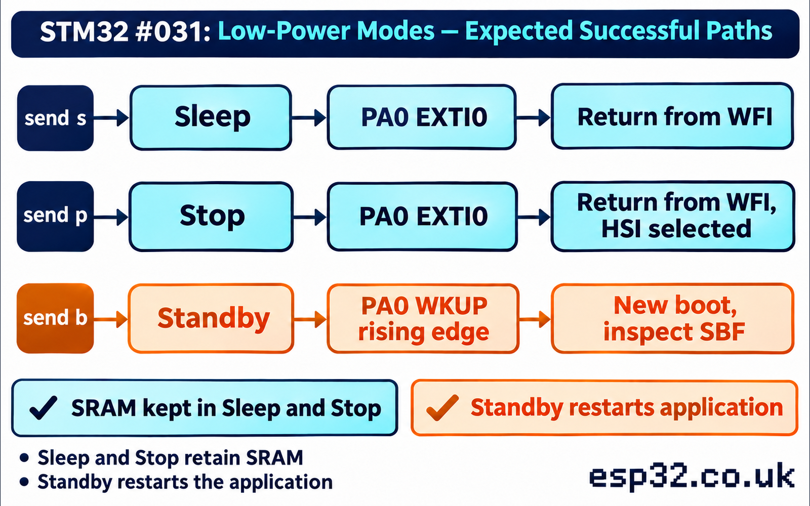
First reset the board, open the terminal and send c. The baseline should report an HCLK of 8 MHz when the project uses the specified direct HSI configuration. Send s, wait about a second after the arming message and press PA0. Look for the Returned from WFI line and an increase in EXTI edges. Sending more serial characters during Sleep may cause other effects if you later add UART interrupts. Use just the button during this test.
Repeat with p. Keep the button released during the short arming window and then press it. You should again see a return from the call. Send c to confirm the example still reports its expected clock. In this HSI-only project, the F103 resumes on the same source the programme used before entry. The firmware continues using the retained USART settings. A different project with an HSE and PLL configuration should have a clock restoration plan before you assume the same result.
Then send b, wait and press PA0. Instead of the same call returning normally, the lab should print the BOOT banner again. SBF=1 is the useful evidence of previous Standby entry. WUF can indicate a wake event, but the bit does not uniquely identify its source. The saved RCC status gives additional reset information. If you press NRST to recover the board instead of using PA0, record that intervention with the observed flags. Try each mode more than once, and test a held button separately to verify the refusal path.
| Trial | Expected serial evidence | What to record alongside it |
|---|---|---|
s, then rising PA0 | Return message and EXTI edge count | Entry-to-press interval and Sleep current |
p, then rising PA0 | Return message and EXTI edge count | Stop current and HCLK after wake |
b, then rising PA0 | New boot banner, SBF set | Standby current and WUF observation |
| Command with PA0 held high | Entry skipped if still high at timeout | Input voltage and pull-down connection |
| Standby call returns | Retry message rather than a boot banner | Any other pending interrupts or debugger activity |
Run one trial in which you leave the button untouched for longer than your normal test interval. If you see a return or reboot before pressing it, capture the time between entry and that event. A consistent short interval points toward a periodic source or reset. An irregular interval can point toward a loose button wire, external circuitry, noise or the debug connection. Repeat after removing one possible source at a time. Keep the other wiring and test steps the same so you can tell which change affected the result.
For a latency trace, use a free GPIO such as PB0 in a separate test build. Drive it low in Run, then set it high immediately after the Sleep or Stop call returns. Trigger the scope on PA0 and measure to the PB0 transition. For Standby, place the PB0 transition at a documented point in startup and use an external pull to define its level while the GPIO is high impedance. The two measurements now have different endpoints. Label the Stop result as return to foreground and the Standby result as time to a named startup milestone. Save the trace and your test firmware revision together.
A serial comparison can reveal the same functional difference without an oscilloscope. In a repeatable sequence, send p, wake the board, send p again and wake it a second time. Two return messages without a boot banner confirm that control returned twice. Then use b and check for exactly the opposite sequence. If the first serial line after wake is lost while your terminal reconnects, it can help to keep the UART connected for functional tests and disconnect it for separate current tests. The results answer different questions.
Restore a PLL clock after Stop
Once the baseline works, you can move to a faster Run clock. Suppose USART1 was configured with PCLK2 at 72 MHz and the retained baud register was programmed for 115200 baud. If PCLK2 falls to 8 MHz on wake while that divider remains in place, the first bytes can arrive at about 12,800 baud. The exact result depends on the clock tree and rounded divider. This is a useful diagnosis when a terminal prints fine before Stop and shows garbage afterwards.
Use a recovery routine that starts the required oscillator, waits with a bounded timeout, enables and waits for PLL if used, then selects the intended SYSCLK and refreshes clock-dependent timing. If the original oscillator fails, handle that as a fallback clock plan and initialise the UART or timers for the actual rate before using them. Consider which interrupts can run during restoration. A small EXTI handler that only sets a flag is simpler than one that immediately touches a timer or serial port whose timebase is wrong.
In an application using the normal HAL tick, make sure that the timebase can advance while clock restoration code waits. Updating a software frequency variable alone does not switch a physical clock or repair a baud divider. The lab intentionally keeps the clock configuration constant across the HSI transition. For a PLL variant, test clock recovery independently of your sensor driver, and verify both HCLK and the peripheral bus rate that determines the driver’s timing. Standby returns through normal startup, so the generated clock setup runs again there.
Measure the board current you actually pay for
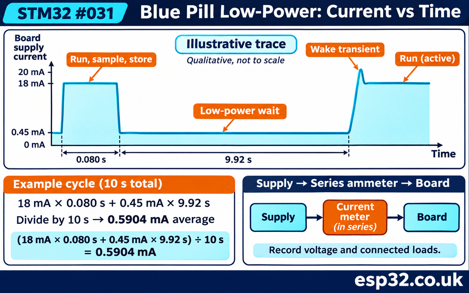
Use the same supply point, voltage and set of attached components for each trial. Start with the board in Run and measure current in series with its supply, or use a current monitor that can show a trace. Record a stable interval in each mode and the wake transient if your instrument captures it. A multimeter in series has a burden voltage. If changing to a more sensitive range causes the MCU to reset, verify the actual voltage at the board and use a measurement setup with adequate range and lower insertion drop.
Measure the development board separately from the MCU datasheet values. The board’s indicator LED, regulator, USB circuitry and connected accessories may consume more current than the chip in Stop or Standby. A value measured at the USB or 5 V input includes the regulator and that input path. A regulated supply at the board’s documented 3.3 V input, where the board supports it, measures a different boundary. State which boundary you used, and avoid feeding competing supplies into the board. ST STM32F103x8/xB electrical characteristics
Disconnect ST-LINK for the power measurement and remove any unrelated cables or modules. Debug settings can keep clocks alive in a low-power mode. For an isolated measurement of a sleeping interval, send the command with the UART connected and then remove the adapter’s signal leads while the board is independently powered. Compare with a run where they stay connected to see if they affect the reading. For a repeated test fixture, use a separate current measurement trigger or a GPIO marker with a known load and clear timing. Give the board time to settle before logging the floor.
Check your test instrument’s limits before interpreting a brief dip. A slow display can blend the active bursts and idle interval into one number. A trace can reveal a repeated early wake or a wake storm from an interrupt flag. A high-resolution low-current measurement can also saturate when the CPU resumes. If the monitor supports both ranges, capture the sleep floor and the active pulse separately, then integrate the charge over the complete cycle.
Write down the board revision, the measured input voltage, the mode, the regulator setting and the connected peripherals. Record whether a USB cable or debugger was attached. For a useful before-and-after comparison, include the same UART log sequence and wait interval on both runs. A later firmware change might remove a peripheral clock and make Sleep look better, while changing a wiring harness might lower the standby floor through a different mechanism. A short setup record is what makes those results comparable a week later.
Check for current leaving the measurement boundary by another path. For example, a UART adapter can hold an input high while the board supply is disconnected, and some modules have pull-ups connected to their own rail. If the board voltage remains above zero during a deliberate main power cut, trace that supply path before treating the measured current as the board’s consumption. For a powered Stop measurement, a peripheral connected to a retained GPIO can also draw current even when its bus is idle. Measure with the peripheral disconnected, then with it connected in the same state, to isolate the difference.
Estimate average current from a complete cycle
Imagine a logger that draws 18 mA for 80 ms while waking, sampling and writing a result. It then spends 9.92 seconds at 0.45 mA. These are example board readings for doing the calculation. The active interval contributes 18 × 0.08 = 1.44 mA·s. The idle interval contributes 0.45 × 9.92 = 4.464 mA·s. Divide their sum by the ten-second period and the average is 0.5904 mA. At that average, the example uses about 14.17 mAh per day.
The two contributions show where to investigate next. At 0.45 mA, the idle portion consumes most of the charge in this example. A board LED or regulator improvement could be more valuable than making the active function a few milliseconds shorter. If the idle current becomes very small, the time spent starting clocks or waiting for a sensor may become the larger part of the budget. Compare the charge of the whole cycle rather than selecting a mode on its idle current alone.
When deciding between Stop and Standby, include the charge needed to restore peripheral configuration after a Standby reboot. For a simplified comparison, suppose one mode saves 0.20 mA during the idle interval and costs an additional 2 mA·s each wake. The idle break-even interval is 2 ÷ 0.20 = 10 seconds, assuming the other parts of the workload are identical. A measured application trace gives you better inputs, especially if a radio, SD card or sensor has its own startup delay. A battery life calculation should also account for available capacity under your load and conditions.
To apply the break-even result, take two otherwise equal jobs that wait three seconds and 30 seconds. In the three-second job, a 0.20 mA saving removes only 0.60 mA·s, less than the extra 2 mA·s spent waking. At 30 seconds, the saving is 6 mA·s and the same wake cost leaves a net 4 mA·s benefit. This is also why a logger with an occasional long gap can benefit from choosing its idle mode based on the next deadline. Test that decision with the actual distribution of intervals and include the cost of preparing a checkpoint before the deepest mode.
Troubleshoot the wake and current together
If Sleep or Stop returns as soon as you send the command, watch the EXTI count and check whether PA0 was already high or bouncing. Verify that SysTick is the HAL timebase and no periodic timer IRQ remains enabled. Look for a stale EXTI pending flag and verify that the correct handler actually calls the HAL clearing routine. A debugger can also cause an immediate return. If you see an edge count of zero and the current never drops, treat that as a clue to inspect other IRQs rather than assuming that the button is broken.
If the button cannot wake Sleep or Stop, measure PA0 released and pressed. Check the GPIO route, the rising-edge selection, the NVIC enable and EXTI0_IRQHandler(). A stable change on the pin with no interrupt count suggests a software configuration problem. A jump straight from zero to a noisy level can mean a missing ground reference or switch wiring problem. A temporary EXTI-only test in Run can prove the pin route before reintroducing WFI.
If Standby wakes instantly, confirm that the pin is low before arming and that the code actually reaches the branch enabling the wake pin. Check any previously configured RTC alarm or watchdog. If the board enters Standby but the button never brings it back, verify the dedicated PA0 WKUP function and check power while pressing. Recovery with NRST is an expected exit. If the chip restarts at intervals you did not command, inspect reset flags and the watchdog configuration. The STM32 watchdog guide shows how to test those reset paths independently.
If your board shows little current difference, compare the same power boundary with the debugger and USB-UART removed. Recheck that the board did not remain in Run after a skipped attempt. Then isolate loads one at a time if your board design allows it. Do not short an LED or bypass a regulator to see whether its current matters. Identify the actual circuit, measure its contribution and modify only a test board whose power path you understand.
Turn the lab into a periodic logger
Use the EXTI button until you can reproduce the expected return and reboot paths. Then move the wake schedule to a source that fits the application. On the STM32F103, a periodic RTC design can set the alarm against the retained counter and rearm it for the next interval. Stop with an RTC alarm uses the alarm’s interrupt/event routing, while Standby wake depends on the dedicated power wake logic. Follow the F1 reference manual and check the alarm and EXTI flags before entering the selected mode.
Store a minimal checkpoint before a Standby cycle, with a validity check appropriate to the data. For example, record the next expected sample time and a sequence number in retained storage that has enough space. On boot, check the retained RTC state, recover the schedule and log whether a sample deadline was missed. Use Stop when retaining the active application state is worth more than the possible idle saving. The lab gives you a way to compare the choices on the actual board, using the observed wake path and the measured charge per sample.