
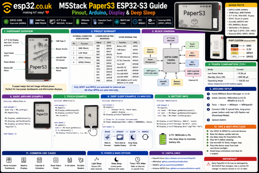
The M5Stack PaperS3 is a complete ESP32-S3 e-paper development device built around an ESP32-S3R8 dual-core 240 MHz processor, 16 MB flash, 8 MB PSRAM, a 4.7-inch 960 × 540 e-ink display, capacitive touch, microSD, RTC, BMI270 IMU, buzzer and an 1800 mAh battery. Unlike a normal ESP32 development board, most GPIOs are already assigned internally; the main external expansion connector exposes GPIO1 and GPIO2 together with 3.3 V and GND. Arduino development is handled cleanly through M5Unified + M5GFX, while the e-paper display makes the PaperS3 particularly attractive for battery dashboards that update briefly and then spend most of their time sleeping.
What is the M5Stack PaperS3?
The PaperS3 is M5Stack’s ESP32-S3 successor to the earlier M5Paper concept.
Instead of being simply an ESP32 development board with a display attached, it is effectively a complete portable e-paper computer containing:
- ESP32-S3
- large e-paper display
- capacitive touchscreen
- rechargeable battery
- real-time clock
- IMU
- buzzer
- microSD slot
- USB
- power-management hardware
- external GPIO connector
The front is dominated by a 4.7-inch 960 × 540 e-ink display capable of 16 levels of grayscale. A GT911 capacitive touch controller provides two-point touch and gesture support.
Because e-paper retains its displayed image without continuously powering the panel, PaperS3 is particularly well suited to applications that display information for long periods between updates.
Typical projects include:
- Home Assistant dashboards
- weather displays
- calendar panels
- room status displays
- electronic labels
- battery-powered sensor displays
- MQTT dashboards
- to-do lists
- information panels
- portable readers
- smart-home control panels
PaperS3 hardware specifications
At the centre of PaperS3 is the ESP32-S3R8.
The main hardware specification is:
| Feature | PaperS3 |
|---|---|
| MCU | ESP32-S3R8 |
| CPU | Dual-core Xtensa LX7 |
| Maximum clock | 240 MHz |
| SRAM | 520 KB |
| PSRAM | 8 MB |
| Flash | 16 MB |
| Wi-Fi | 2.4 GHz |
| Display | 4.7-inch E-Ink |
| Resolution | 960 × 540 |
| Grayscale | 16 levels |
| Touch | GT911 capacitive |
| Touch points | Up to 2 |
| IMU | BMI270 |
| RTC | BM8563 |
| Storage | microSD |
| Battery | 1800 mAh |
| USB | OTG / CDC / MSC / flashing |
| External GPIO | GPIO1 + GPIO2 |
| Buzzer | Passive buzzer |
M5Stack specifies the ESP32-S3R8 at up to 240 MHz, with 16 MB external flash and 8 MB quad PSRAM on PaperS3.
That gives PaperS3 considerably more memory than many basic ESP32 boards and is useful when dealing with large 960 × 540 graphics buffers.
PaperS3 vs the original M5Paper
PaperS3 should not be confused with the older M5Paper.
The original M5Paper used the original dual-core ESP32 generation, while PaperS3 moves to the newer ESP32-S3R8 platform. PaperS3 also increases the battery from the earlier M5Paper’s 1150 mAh to 1800 mAh, adds a BMI270 IMU and provides USB OTG functionality.
Both share the general concept of a large 4.7-inch touch e-paper device, but PaperS3 is the much more modern platform for new Arduino development.
PaperS3 pinout overview
PaperS3 is very different from an ESP32 DevKit.
There are not two rows of unused GPIO headers around the board.
Most of the ESP32-S3 GPIOs are already permanently assigned to:
- the e-paper display
- touchscreen
- internal I²C bus
- microSD
- battery sensing
- buzzer
- USB detection
- internal hardware
The main user-accessible external connector exposes just:
GND
3V3
GPIO1
GPIO2
M5Stack labels this connector PORT.CUSTOM.
External expansion connector
The four-pin HC1.25 connector is mapped as:
| Connector wire | Function |
|---|---|
| Black | GND |
| Red | 3.3 V |
| Yellow | GPIO1 |
| White | GPIO2 |
This is the most important pinout information for most PaperS3 projects because GPIO1 and GPIO2 are the intended external GPIOs.
They can be used for applications such as:
- I²C sensors
- digital sensors
- buttons
- external ADCs
- OneWire devices
- UART devices
- simple relay-driver circuits
The ESP32-S3 GPIO matrix allows peripheral functions to be assigned flexibly, so GPIO1/GPIO2 are not permanently limited to one protocol.
E-paper display GPIO mapping
The 4.7-inch ED047TC1 e-paper panel consumes a large number of GPIOs.
M5Stack documents the display mapping as:
| E-Paper signal | ESP32-S3 GPIO |
|---|---|
| DB0 | GPIO6 |
| DB1 | GPIO14 |
| DB2 | GPIO7 |
| DB3 | GPIO12 |
| DB4 | GPIO9 |
| DB5 | GPIO11 |
| DB6 | GPIO8 |
| DB7 | GPIO10 |
| XSTL | GPIO13 |
| XLE | GPIO15 |
| SPV | GPIO17 |
| CKV | GPIO18 |
| PWR | GPIO45 |
These GPIOs should be considered reserved for the e-paper display.
This is one reason generic ESP32-S3 pinout diagrams are not particularly useful for PaperS3: a GPIO may technically exist on the chip but already have a critical board-level function.
Touchscreen and internal I²C pins
The GT911 capacitive touchscreen uses:
GPIO41 → SDA
GPIO42 → SCL
GPIO48 → Touch interrupt
The same GPIO41/GPIO42 internal I²C bus is also shared with other internal peripherals such as the BM8563 real-time clock.
For most Arduino projects, these devices should be accessed through M5Unified rather than manually reconfiguring their GPIOs.
Battery monitoring and buzzer pins
PaperS3 also assigns:
GPIO3  → Battery voltage ADC
GPIO21 → Buzzer PWM
The M5Unified power API provides functions to access battery level, voltage and charging status directly, so there is normally no need to manually call analogRead(3).
For example:
int battery = M5.Power.getBatteryLevel();
int voltage = M5.Power.getBatteryVoltage();
bool charging = M5.Power.isCharging();
getBatteryLevel() provides an estimated percentage, while getBatteryVoltage() returns battery voltage in millivolts.
microSD pinout
PaperS3’s microSD slot uses SPI:
| microSD | ESP32-S3 |
|---|---|
| CS | GPIO47 |
| SCK | GPIO39 |
| MOSI | GPIO38 |
| MISO | GPIO40 |
These pins should be reserved if the built-in SD card slot is required.
M5Stack’s Arduino example initializes the bus as:
#define SD_SPI_CS_PIN   47
#define SD_SPI_SCK_PIN  39
#define SD_SPI_MOSI_PIN 38
#define SD_SPI_MISO_PIN 40

SPI.begin(
  SD_SPI_SCK_PIN,
  SD_SPI_MISO_PIN,
  SD_SPI_MOSI_PIN,
  SD_SPI_CS_PIN
);

SD.begin(SD_SPI_CS_PIN, SPI, 25000000);
The official example uses a 25 MHz SPI clock for the microSD interface.
USB detection
GPIO5 is internally used to detect whether USB power is present.
M5Stack specifies:
GPIO5 → USB_DET
A USB detection voltage above approximately 0.2 V indicates that USB power is connected.
GPIO5 should therefore not be treated as a spare external GPIO.
Quick PaperS3 GPIO reference
For practical projects, the easiest mental model is:
| GPIO | Function |
|---|---|
| GPIO1 | ✅ External user GPIO |
| GPIO2 | ✅ External user GPIO |
| GPIO3 | Battery ADC |
| GPIO5 | USB detection |
| GPIO6–18 | Mainly e-paper display |
| GPIO21 | Buzzer |
| GPIO38–40, 47 | microSD |
| GPIO41/42 | Internal I²C |
| GPIO45 | E-paper power |
| GPIO48 | Touch interrupt |
The key rule is simple:
Use GPIO1 and GPIO2 for external hardware unless there is a specific reason to work directly with one of the internally assigned pins.
Using GPIO1 and GPIO2 as I²C
One particularly useful configuration is:
GPIO1 → SDA
GPIO2 → SCL
For example:
#include <Wire.h>

void setup() {
  Wire.begin(1, 2);
}

void loop() {
}
That gives PaperS3 a convenient external I²C connection for devices such as:
Because the connector provides 3.3 V, it is particularly convenient for 3.3 V I²C sensor boards.
Arduino IDE setup
PaperS3 has dedicated support in M5Stack’s Arduino board package.
M5Stack’s current PaperS3 Arduino documentation specifies at least:
- M5Stack Board Manager 2.1.4
- Board selection: M5PaperS3
- M5Unified 0.2.5
- M5GFX 0.2.7
or later versions.
Install:
M5Unified
M5GFX
through Arduino Library Manager.
Modern PaperS3 projects no longer need to install the epdiy library separately when using the current M5Unified/M5GFX setup.
Select the correct Arduino board
In Arduino IDE select:
Tools
→ Board
→ M5Stack
→ M5PaperS3
Using the dedicated PaperS3 board definition is preferable to treating it as a generic ESP32-S3 board because the M5 libraries then know which internal display, power, touch and peripheral configuration is present.
Entering firmware download mode
If Arduino IDE cannot upload normally, PaperS3 can be manually placed into download mode.
Connect USB, then:
Long-press the PaperS3 power button until the rear status LED flashes red.
The device is then in firmware-download mode and its USB port should become available to Arduino IDE.
Basic Arduino Hello World example
The easiest way to start is with M5Unified:
#include <M5Unified.h>

void setup() {
  auto cfg = M5.config();
  M5.begin(cfg);

  M5.Display.setTextSize(3);
  M5.Display.println("Hello PaperS3!");
}

void loop() {
}
M5.begin() initializes the device, while M5.Display provides the unified M5GFX display interface. M5Unified deliberately uses the same display API across supported M5Stack LCD and e-paper devices.
Setting display rotation
Rotation can be changed with:
M5.Display.setRotation(0);
or:
M5.Display.setRotation(1);
This is useful because PaperS3’s 960 × 540 panel can work naturally as either a portrait-style interface or a wide landscape dashboard.
For example:
#include <M5Unified.h>

void setup() {
  M5.begin();

  M5.Display.setRotation(1);
  M5.Display.setTextSize(3);

  M5.Display.println("PaperS3 Dashboard");
}

void loop() {
}
M5Stack’s own PaperS3 examples use setRotation() extensively for display orientation.
Drawing graphics
M5GFX provides familiar graphics functions such as:
M5.Display.drawLine();
M5.Display.drawRect();
M5.Display.fillRect();
M5.Display.drawCircle();
M5.Display.fillCircle();
M5.Display.drawString();
M5.Display.printf();
This makes PaperS3 programming feel very similar to drawing on an ESP32 TFT display even though the underlying screen technology is completely different. M5Unified’s display API is built on M5GFX specifically to give M5Stack devices a common graphics interface.
A simple PaperS3 dashboard example
#include <M5Unified.h>

void setup() {
  M5.begin();

  M5.Display.setRotation(1);
  M5.Display.clear();

  M5.Display.setTextSize(2);

  M5.Display.setCursor(40, 40);
  M5.Display.println("Living Room");

  M5.Display.setTextSize(4);

  M5.Display.setCursor(40, 130);
  M5.Display.println("22.8 C");

  M5.Display.setCursor(40, 240);
  M5.Display.println("48 % RH");

  M5.Display.setTextSize(2);

  M5.Display.setCursor(40, 380);
  M5.Display.println("Last update: 10:35");
}

void loop() {
}
This style of application is particularly appropriate for e-paper because the displayed values can remain visible after the processor and display-driving circuitry enter a low-power state. PaperS3’s e-ink panel explicitly supports image retention without continuous panel power.
E-paper is not an LCD
One important programming habit should change when moving from a TFT to PaperS3.
A conventional TFT application might redraw continuously:
void loop() {
  drawScreen();
  delay(50);
}
That style makes little sense for most e-paper projects.
The PaperS3 is much better suited to:
Wake
↓
Fetch new data
↓
Update screen
↓
Sleep
↓
Wake later
The display can retain the previous image while the rest of the device sleeps or powers down, which is precisely what makes e-paper useful for long-lived battery dashboards.
Using the touchscreen
PaperS3 uses a GT911 capacitive touchscreen supporting up to two touch points and gesture operations.
With M5Unified, touch handling is straightforward:
#include <M5Unified.h>

void setup() {
  M5.begin();

  M5.Display.setRotation(0);
  M5.Display.println("Touch the screen");
}

void loop() {
  M5.update();

  auto touch = M5.Touch.getDetail();

  if (touch.isPressed()) {
    M5.Display.fillCircle(
      touch.x,
      touch.y,
      10
    );
  }
}
M5Stack’s official example uses the same M5.Touch.getDetail() approach to read touch coordinates and draw directly at the touched position.
Why M5.update() matters
Many M5Unified examples include:
M5.update();
inside loop().
This refreshes the state of M5Unified-managed inputs such as touch and buttons.
So for interactive applications, a typical loop is:
void loop() {
  M5.update();

  auto touch = M5.Touch.getDetail();

  if (touch.isPressed()) {
    // respond to touch
  }
}
M5Stack’s PaperS3 touchscreen example calls M5.update() before querying the GT911 touch state.
Using the BMI270 IMU
PaperS3 contains a BMI270 six-axis IMU.
The device can provide:
- X/Y/Z acceleration
- X/Y/Z angular velocity
M5Stack documents the BMI270 at I²C address 0x68.
With M5Unified:
m5::imu_data_t imuData;

void loop() {
  M5.Imu.update();

  imuData = M5.Imu.getImuData();

  Serial.printf(
    "Accel X: %.2f Y: %.2f Z: %.2fn",
    imuData.accel.x,
    imuData.accel.y,
    imuData.accel.z
  );
}
This is essentially the same API used by M5Stack’s official PaperS3 IMU example.
Possible uses include:
- automatic display orientation
- motion wake-up logic
- tilt controls
- portable dashboards
- activity detection
Using the buzzer
PaperS3 contains a passive buzzer connected internally to GPIO21.
M5Unified treats it through the speaker interface:
M5.Speaker.setVolume(150);
M5.Speaker.tone(1000, 200);
The official PaperS3 buzzer example uses M5.Speaker.tone() to generate different audio frequencies.
For a dashboard, that can provide simple:
- alerts
- button feedback
- alarms
- timer notifications
Using the microSD card
PaperS3 supports microSD expansion.
The official Arduino example uses the standard Arduino SD library together with M5GFX.
A simplified initialization looks like:
#include <SPI.h>
#include <SD.h>
#include <M5Unified.h>

#define SD_CS   47
#define SD_SCK  39
#define SD_MOSI 38
#define SD_MISO 40

void setup() {
  M5.begin();

  SPI.begin(
    SD_SCK,
    SD_MISO,
    SD_MOSI,
    SD_CS
  );

  if (SD.begin(SD_CS, SPI, 25000000)) {
    M5.Display.println("SD card detected");
  } else {
    M5.Display.println("SD card error");
  }
}

void loop() {
}
The microSD card is particularly useful for:
- offline images
- fonts
- logs
- cached weather data
- configuration
- e-books
- dashboard resources
Displaying PNG images from microSD
M5GFX can draw PNG files directly from an SD card.
For example:
M5.Display.drawPngFile(
  SD,
  "/dashboard.png"
);
M5Stack’s PaperS3 SD example uses drawPngFile() to display 960 × 540 PNG images stored on the card.
For best results, creating graphics at the native:
960 × 540
resolution avoids unnecessary scaling.
Battery
PaperS3 contains a:
3.7 V 1800 mAh lithium battery
with an onboard charging circuit.
Battery information can be queried directly:
bool charging =
  M5.Power.isCharging();

int battery =
  M5.Power.getBatteryLevel();

int voltage =
  M5.Power.getBatteryVoltage();
The voltage value is returned in millivolts.
For example:
M5.Display.printf(
  "Battery: %d%%n",
  M5.Power.getBatteryLevel()
);
Why deep sleep matters so much on PaperS3
PaperS3’s hardware architecture is particularly well suited to deep sleep because the display does not need to be continuously refreshed.
Imagine a weather display that only changes every 15 minutes.
Keeping:
- ESP32-S3
- Wi-Fi
- CPU
- IMU
- supporting electronics
fully running for those 15 minutes wastes energy.
A better design is:
Wake
↓
Connect Wi-Fi
↓
Download weather data
↓
Update e-paper
↓
Sleep for 15 minutes
M5Stack specifically provides PaperS3 support for light sleep, deep sleep and timer-based sleep through the M5Unified Power_Class.
Light sleep
Light sleep temporarily pauses most processing but retains the running application.
M5Stack’s example uses:
M5.Power.lightSleep(
  5000000,
  false
);
The first argument is in microseconds, so:
5,000,000 µs = 5 seconds
After wake-up, program execution continues from the next line.
Example:
M5.Display.println("Sleeping...");

M5.Power.lightSleep(
  5000000,
  false
);

M5.Display.println("Awake!");
Deep sleep
Deep sleep provides a much stronger reduction in processor power.
PaperS3 can enter timed deep sleep using:
M5.Power.deepSleep(
  5000000,
  false
);
Again, the time is specified in microseconds.
The important behavioural difference is that after waking from deep sleep, the ESP32-S3 restarts the program from setup() rather than continuing from the next line. M5Stack explicitly notes this difference in its PaperS3 wake-up tutorial.
So code should be designed as:
void setup() {

  M5.begin();

  // read sensors
  // connect Wi-Fi
  // update display

  M5.Power.deepSleep(
    60ULL * 1000000ULL,
    false
  );
}

void loop() {
}
That example wakes approximately once per minute.
Timer sleep
M5Unified also exposes:
M5.Power.timerSleep(5);
where the argument is specified in seconds in M5Stack’s PaperS3 example.
The official example presents:
M5.Power.timerSleep(5);
as an alternative to direct ESP32 deep sleep for timed sleep/wake operation.
A practical 15-minute e-paper dashboard
A battery-oriented project could look conceptually like this:
#include <M5Unified.h>
#include <WiFi.h>

void setup() {

  M5.begin();

  M5.Display.setRotation(1);

  WiFi.begin(
    "YOUR_SSID",
    "YOUR_PASSWORD"
  );

  while (
    WiFi.status() != WL_CONNECTED
  ) {
    delay(100);
  }

  // Fetch data here

  M5.Display.clear();
  M5.Display.setTextSize(3);

  M5.Display.println(
    "Weather"
  );

  M5.Display.println(
    "22.4 C"
  );

  WiFi.disconnect(true);

  M5.Power.deepSleep(
    15ULL * 60ULL * 1000000ULL,
    false
  );
}

void loop() {
}
Because deep-sleep wake-up restarts execution from setup(), this wake-update-sleep structure fits the PaperS3 particularly well.
PaperS3 power consumption
M5Stack publishes three useful operating figures for PaperS3:
| State | Published consumption |
|---|---|
| Low-power mode | ~9.28 µA |
| Standby with gyroscope on | ~949.58 µA |
| Operating mode | ~154.02 mA |
These figures were measured at a 4.2 V battery supply under M5Stack’s stated configurations.
The difference illustrates why power-state management matters:
Operating
~154 mA

vs

lowest published mode
~0.009 mA
Actual battery life will depend heavily on how frequently the ESP32 wakes, how long Wi-Fi remains active, how often the e-paper refreshes, peripheral activity and battery condition.
E-paper retains its image while sleeping
One of PaperS3’s biggest advantages is that entering low power does not require the screen to become blank.
The e-paper panel retains its previous image without continuous display power.
That allows a project to:
Display:
22.5°C
48% RH
Updated 12:30

↓
Deep sleep

Screen still shows:
22.5°C
48% RH
Updated 12:30
while the ESP32 consumes far less power.
This behaviour is what makes PaperS3 fundamentally different from most TFT-based ESP32 dashboards.
RTC and timed wake-up
PaperS3 includes a BM8563 real-time clock at I²C address 0x51. M5Stack specifically lists RTC sleep/wake support as a PaperS3 hardware feature.
This is useful for applications that need to wake according to actual clock time rather than simply “N minutes from now.”
Examples include:
Wake at 07:00
→ update weather

Wake at 12:00
→ update calendar

Wake at 18:00
→ update commute information

Sleep overnight
M5Unified provides RTC APIs through its RTC8563_Class.
Ideal architecture for Home Assistant dashboards
PaperS3 can make an excellent Home Assistant information panel, but the best architecture depends on the required refresh rate.
For a display showing:
- temperature
- humidity
- weather
- alarm status
- doors/windows
- energy consumption
- calendar events
there is rarely any reason to redraw every second.
A more e-paper-friendly approach is:
Wake every 5–15 minutes
↓
Connect to Wi-Fi
↓
Request Home Assistant / MQTT data
↓
Draw entire dashboard
↓
Disconnect Wi-Fi
↓
Deep sleep
That architecture takes advantage of both the ESP32-S3’s connectivity and the e-paper panel’s ability to retain the image when the rest of the system sleeps.
GPIO expansion limitations
PaperS3 is not the best choice when a project requires ten exposed GPIOs.
Only GPIO1 and GPIO2 are provided through the normal external expansion connector.
If more GPIOs are needed, a sensible approach is to add an external expander such as:
over I²C.
That turns:
GPIO1 = SDA
GPIO2 = SCL
into many additional digital I/O pins without interfering with PaperS3’s internal hardware.
PaperS3 version warning
M5Stack documents an important charging warning for early PaperS3 batches.
Due to USB timing issues affecting QC3.0/2.0 negotiation, early units may be exposed to damaging high voltage when used with certain QC chargers.
M5Stack states that PaperS3 v1.1/v1.2 and later do not have this issue.
For an early PaperS3 whose revision is unknown, avoid QC3.0/2.0 fast chargers and use a normal 5 V USB supply.
M5Stack states that versions v1.1/v1.2 and later have the version printed on a rear sticker, while v1.0 does not show version information there.
Common problem: Arduino code will not compile
Make sure Arduino IDE is configured for:
Board:
M5PaperS3
and that current versions of:
M5Unified
M5GFX
are installed.
M5Stack’s current PaperS3 Arduino instructions specify M5Unified 0.2.5 and M5GFX 0.2.7 as minimum versions, and note that the separate epdiy dependency used by older setups is no longer required with the current stack.
Common problem: upload port does not appear
Connect PaperS3 by USB and long-press its power button.
When the rear status LED starts flashing red, PaperS3 has entered download mode.
Then select the newly appearing port in Arduino IDE and upload again.
Common problem: display works but touch does not
Interactive applications should call:
M5.update();
inside loop() before reading:
M5.Touch.getDetail();
M5Stack’s official touchscreen example uses this exact sequence.
Common problem: microSD card not detected
Verify that the PaperS3-specific SPI mapping is being used:
CS   = GPIO47
SCK  = GPIO39
MOSI = GPIO38
MISO = GPIO40
and initialize the bus before SD.begin().
M5Stack’s example also specifies FAT32 for its demonstration card.
Common problem: battery drains much faster than expected
Check whether the device is actually entering deep/low-power mode.
Leaving:
- Wi-Fi connected
- ESP32-S3 fully active
- IMU running
- frequent display updates
will consume vastly more energy than an application that wakes briefly and then sleeps.
M5Stack’s own figures range from roughly 154 mA operating down to 9.28 µA in its published lowest-power configuration, illustrating how dramatically firmware architecture affects battery life.
Best uses for PaperS3
PaperS3 is particularly well suited to projects where information changes relatively slowly.
Home Assistant dashboard
Display:
- room temperature
- humidity
- weather
- alarm state
- energy usage
- door/window state
and refresh periodically.
Desk calendar
Show:
- date
- appointments
- reminders
- weather
and wake only when new data is required.
Battery sensor display
Connect an external sensor through GPIO1/GPIO2, update the screen and sleep.
Electronic status panel
Use the magnetic rear mounting to attach it to a refrigerator, cabinet, rack or wall-mounted plate.
Portable information terminal
Use touch, SD storage, RTC and the large high-resolution display for offline reference data or menus.
Who should buy PaperS3?
PaperS3 makes the most sense when the project benefits from:
- a large e-paper screen
- excellent readability
- long periods between updates
- touch input
- portable battery operation
- Wi-Fi
- a complete enclosed device
- minimal external wiring
It is less suitable when:
- many exposed GPIOs are required
- the UI must animate continuously
- video is required
- extremely fast screen updates are important
The design is fundamentally optimized around information display rather than high-refresh graphics. Its 960 × 540 e-paper panel, touch controller, battery and sleep-capable power design make that clear.
Final recommendation
The M5Stack PaperS3 is one of the more interesting ESP32-S3 devices for projects where the screen itself is the main feature.
Its strongest combination is:
ESP32-S3R8 + 16 MB flash + 8 MB PSRAM + 960 × 540 e-paper + touch + 1800 mAh battery + RTC
all in one finished device.
For Arduino development, start with:
#include <M5Unified.h>
initialize using:
M5.begin();
and use:
M5.Display
M5.Touch
M5.Power
M5.Imu
M5.Rtc
for the major onboard functions. M5Unified officially supports M5PaperS3 and uses M5GFX for its graphics layer.
For external sensors, treat:
GPIO1
GPIO2
as the normal expansion GPIOs and leave the internally assigned display, SD, touch and power-management pins alone.
And for battery projects, design the software around the real strength of e-paper:
wake → update → sleep → leave the image visible.
That is where PaperS3 becomes much more useful than simply attaching another display to an ESP32 development board.