
The AI-Thinker ESP32-CAM has far fewer genuinely free GPIOs than a normal ESP32 development board because the OV2640 camera, PSRAM, microSD slot, flash LED and UART already consume many pins. With the camera enabled but the microSD card unused, GPIO13 and GPIO14 are the best general-purpose GPIOs, while GPIO4 can also be used if the onboard flash LED is not required. GPIO0, GPIO2, GPIO5, GPIO12 and GPIO15 are ESP32 strapping pins and need extra care during boot. GPIO0 is also the camera clock, GPIO4 drives the bright flash LED, GPIO16 is normally tied to PSRAM, and GPIO1/GPIO3 are used for programming and Serial.
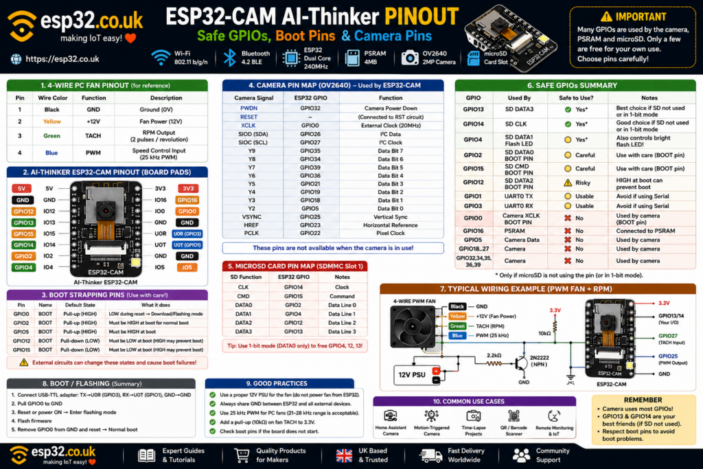
1. ESP32-CAM AI-Thinker overview
The AI-Thinker ESP32-CAM combines a classic ESP32 with:
- Wi-Fi
- Bluetooth
- OV2640 camera connector
- PSRAM
- microSD card slot
- bright white flash LED
- PCB antenna
- external antenna option
- a small number of exposed GPIOs
It is an excellent low-cost board for:
- security cameras
- Home Assistant camera nodes
- time-lapse photography
- image capture
- QR/barcode projects
- object detection experiments
- remote monitoring
The disadvantage is pin availability.
A normal ESP32 DevKit exposes a large number of GPIOs. On the ESP32-CAM, most of those GPIOs are already assigned internally to the camera and memory.
That makes understanding the pinout much more important.
2. Quick safe GPIO cheat sheet
For an AI-Thinker ESP32-CAM with the camera active, this is the most useful practical summary:
| GPIO | Main board use | Recommendation |
|---|---|---|
| GPIO13 | microSD D3 | ✅ Best general GPIO if SD unused |
| GPIO14 | microSD CLK | ✅ Good general GPIO if SD unused |
| GPIO4 | Flash LED + microSD D1 | ✅ Usable if LED/SD unused |
| GPIO2 | microSD D0 + strapping | ⚠️ Use with care |
| GPIO12 | microSD D2 + strapping | ⚠️ Avoid for beginner projects |
| GPIO15 | microSD CMD + strapping | ⚠️ Use with care |
| GPIO1 | UART0 TX | ⚠️ Serial/programming |
| GPIO3 | UART0 RX | ⚠️ Serial/programming |
| GPIO0 | Camera XCLK + boot strap | ❌ Not free with camera |
| GPIO16 | PSRAM | ❌ Avoid |
| GPIO5 | Camera data | ❌ Camera |
| GPIO18–27 | Camera | ❌ Camera |
| GPIO32 | Camera power-down | ❌ Camera |
| GPIO34–39 | Camera data | ❌ Camera |
The official Espressif Arduino camera example defines the AI-Thinker camera using GPIO0, 5, 18, 19, 21, 22, 23, 25, 26, 27, 32, 34, 35, 36 and 39.
3. AI-Thinker ESP32-CAM camera pin mapping
The camera pin mapping is not arbitrary.
Espressif’s official CameraWebServer example defines the AI-Thinker board as follows:
| Camera signal | ESP32 GPIO |
|---|---|
| PWDN | GPIO32 |
| RESET | Not connected / software reset |
| XCLK | GPIO0 |
| SIOD / SDA | GPIO26 |
| SIOC / SCL | GPIO27 |
| Y9 | GPIO35 |
| Y8 | GPIO34 |
| Y7 | GPIO39 |
| Y6 | GPIO36 |
| Y5 | GPIO21 |
| Y4 | GPIO19 |
| Y3 | GPIO18 |
| Y2 | GPIO5 |
| VSYNC | GPIO25 |
| HREF | GPIO23 |
| PCLK | GPIO22 |
These pins should be considered reserved whenever the camera is being used.
4. Why so many GPIOs disappear
A camera such as the OV2640 sends image data to the ESP32 over a parallel interface.
The connection requires:
- eight image data signals
- pixel clock
- horizontal reference
- vertical sync
- external clock
- I²C-style camera configuration signals
- camera power control
That consumes a large number of GPIOs before any sensors, relays or buttons are added.
This is the fundamental limitation of the original ESP32-CAM design.
5. GPIO0: boot pin and camera clock
GPIO0 has two critical roles.
First, it is an ESP32 boot-strapping pin.
Second, the AI-Thinker camera uses it as XCLK, the external camera clock.
For normal ESP32 boot:
GPIO0 HIGH
→ boot firmware from flash
For firmware download mode:
GPIO0 LOW during reset
→ serial bootloader / flashing mode
This is why the normal ESP32-CAM upload procedure involves connecting:
GPIO0 → GND
before reset or power-up.
After flashing:
- Remove GPIO0 from GND.
- Reset the board.
- The ESP32 boots normally.
Espressif’s boot documentation confirms that GPIO0 is used to select download boot versus normal SPI-flash boot.
Can GPIO0 be used for another device?
Not realistically while the camera is operating.
The OV2640 needs GPIO0 as its XCLK input.
Treat it as:
Camera only + programming boot control.
6. The real ESP32 boot/strapping pins
The classic ESP32 has five main strapping GPIOs:
- GPIO0
- GPIO2
- GPIO5
- GPIO12
- GPIO15
Espressif officially identifies these pins as strapping pins sampled during reset. After boot, they can normally operate as regular GPIOs.
However, hardware connected to them can alter the boot configuration.
On the ESP32-CAM, three exposed strapping pins deserve particular attention:
GPIO2
GPIO12
GPIO15
GPIO0 is already occupied by the camera, and GPIO5 is an internal camera data line.
7. GPIO12: the dangerous one
GPIO12 deserves the strongest warning.
It is the ESP32’s MTDI strapping pin and participates in selecting the flash interface voltage during reset. Espressif documents GPIO12 as a strapping pin, with a default pull-down state.
Pulling GPIO12 HIGH during boot on a design expecting the normal flash voltage can prevent the ESP32 from starting correctly.
Typical symptoms include:
- boot loops
- unreadable boot messages
- flash errors
- board appears dead until peripheral is disconnected
For beginner projects:
Do not choose GPIO12 first.
GPIO13 or GPIO14 are usually much easier.
8. GPIO2
GPIO2 is also a boot-strapping pin.
Espressif’s boot configuration documentation shows that GPIO0 and GPIO2 participate in selecting normal SPI boot versus download boot.
GPIO2 is also connected to the ESP32-CAM’s microSD interface as DATA0.
So GPIO2 is usable only when:
- the microSD interface is not using it
- external hardware does not force the wrong state during reset
For a simple button or sensor, GPIO13 or GPIO14 are preferable.
9. GPIO15
GPIO15 is another ESP32 strapping pin and also the microSD CMD signal.
Espressif documents GPIO15 as MTDO and a strapping pin.
It can be used after startup when the microSD slot is unused, but external pull resistors or devices attached to it can affect reset behaviour.
Use it only after the simpler GPIO choices have been exhausted.
10. GPIO13: probably the best spare pin
If the camera is running and the microSD slot is not being used, GPIO13 is usually the best exposed general-purpose GPIO on the AI-Thinker ESP32-CAM.
GPIO13:
- is not a boot-strapping pin
- can act as digital input/output
- supports PWM
- supports ADC2
- supports touch
- is normally assigned to microSD D3
The main restriction is therefore the microSD card.
If no SD card is being used, GPIO13 is an excellent choice for:
- PIR sensor
- DS18B20
- relay driver
- button
- status LED
- digital input
- PWM control
It also has a JTAG function, but that is irrelevant for most Arduino/ESPHome projects. Espressif lists GPIO13 as ADC2_CH4 / JTAG rather than a strapping pin.
11. GPIO14: another good spare GPIO
GPIO14 is another useful pin when the microSD card is disabled.
It is normally the SD card clock signal.
GPIO14:
- is digital input/output capable
- supports PWM
- supports ADC2
- supports touch
- is not a boot strap
Like GPIO13, it also has a JTAG alternate function.
For many ESP32-CAM projects, GPIO13 and GPIO14 should be the first two pins considered.
12. GPIO4: useful, but connected to the flash LED
GPIO4 is exposed and is not one of the classic ESP32 strapping pins.
However, it has two important board-level functions.
It is used as:
- microSD DATA1
- onboard bright camera flash LED
Espressif’s current AI-Thinker camera definition identifies GPIO4 as the flash LED pin.
This means code such as:
pinMode(4, OUTPUT);
digitalWrite(4, HIGH);
will turn on the bright white onboard LED on typical AI-Thinker boards.
Can GPIO4 control something else?
Yes, if:
- the microSD card is not using DATA1
- the flash LED turning on is acceptable, or the board is modified
But any signal sent to GPIO4 will also affect the LED.
For this reason:
GPIO13/14 are cleaner choices.
13. GPIO1 and GPIO3: UART programming pins
The ESP32-CAM has no normal onboard USB connector.
Programming is typically done through UART0.
The relevant pins are:
- GPIO1 = U0TXD
- GPIO3 = U0RXD
Espressif identifies GPIO1 and GPIO3 as the ESP32’s normal TXD and RXD pins.
Typical USB-to-TTL connection:
| USB-TTL | ESP32-CAM |
|---|---|
| TX | U0R / GPIO3 |
| RX | U0T / GPIO1 |
| GND | GND |
| Power | appropriate board supply |
Remember:
TX connects to RX.
RX connects to TX.
Can GPIO1 and GPIO3 be reused?
Yes, after boot, provided Serial communication is no longer needed.
But using them may:
- interfere with programming
- interfere with Serial Monitor
- print boot/debug data to attached hardware
- make troubleshooting harder
They are therefore usable but not preferred.
14. GPIO16 and PSRAM
GPIO16 is physically exposed on many AI-Thinker ESP32-CAM boards, which makes it tempting to use.
Don’t.
Espressif notes that GPIO16 and GPIO17 are commonly connected to flash/PSRAM on ESP32 modules and therefore should not normally be used for other purposes.
The ESP32-CAM relies heavily on PSRAM for higher-resolution camera operation and larger frame buffers.
Espressif’s official camera example explicitly notes that PSRAM is required for UXGA resolution and high JPEG quality.
Treat GPIO16 as:
reserved for PSRAM.
15. The onboard microSD card uses six GPIOs
The ESP32’s SDMMC Slot 1 uses:
| SD function | GPIO |
|---|---|
| CLK | GPIO14 |
| CMD | GPIO15 |
| DATA0 | GPIO2 |
| DATA1 | GPIO4 |
| DATA2 | GPIO12 |
| DATA3 | GPIO13 |
Espressif documents exactly this Slot 1 pin mapping.
These are the same GPIO group connected to the ESP32-CAM microSD slot.
So when the card is operating in full 4-bit SD mode, almost every useful exposed GPIO disappears.
16. ESP32-CAM with microSD in 4-bit mode
With the camera active and microSD using its full 4-bit bus:
GPIO2  → SD DATA0
GPIO4  → SD DATA1
GPIO12 → SD DATA2
GPIO13 → SD DATA3
GPIO14 → SD CLK
GPIO15 → SD CMD
That leaves virtually no clean general-purpose GPIO.
GPIO1 and GPIO3 are still physically accessible, but they are UART0.
GPIO0 belongs to the camera.
GPIO16 belongs to PSRAM.
This is why adding peripherals to an ESP32-CAM that simultaneously uses:
camera + PSRAM + full microSD
is difficult.
17. The useful trick: microSD 1-bit mode
The ESP32 SDMMC controller supports both 1-line and 4-line SD operation.
In 1-bit mode only these SD signals are required:
- CLK → GPIO14
- CMD → GPIO15
- DATA0 → GPIO2
That means these become available again:
- GPIO4
- GPIO12
- GPIO13
This is extremely useful on the ESP32-CAM.
Best spare GPIO in 1-bit SD mode
GPIO13
GPIO4 still controls the flash LED.
GPIO12 remains a dangerous strapping pin.
So GPIO13 becomes the obvious external peripheral pin.
18. Arduino microSD 1-bit example
With Arduino’s SD_MMC library, 1-bit mode is commonly selected with the second parameter of begin():
#include "SD_MMC.h"

void setup() {
  SD_MMC.begin("/sdcard", true);
}

void loop() {
}
The important design idea is simply that using a 1-bit SD bus reduces the number of required SD data lines, freeing GPIOs that would otherwise be occupied.
19. Camera pins that should never be reused
With the camera active, avoid all of these:
| GPIO | Camera function |
|---|---|
| 0 | XCLK |
| 5 | Y2 |
| 18 | Y3 |
| 19 | Y4 |
| 21 | Y5 |
| 22 | PCLK |
| 23 | HREF |
| 25 | VSYNC |
| 26 | SIOD |
| 27 | SIOC |
| 32 | PWDN |
| 34 | Y8 |
| 35 | Y9 |
| 36 | Y6 |
| 39 | Y7 |
This mapping comes directly from Espressif’s current Arduino ESP32 AI-Thinker camera configuration.
GPIO34, GPIO35, GPIO36 and GPIO39 are input-only on the original ESP32 anyway.
20. GPIO34–39 are input-only
On a normal ESP32, GPIO34–GPIO39 are special because they lack output drivers.
Espressif documents GPIO34, GPIO35, GPIO36 and GPIO39 as GPI, meaning general-purpose input only.
They also lack software-controlled internal pull-ups/pull-downs.
On the ESP32-CAM this matters less because several of them are already occupied by camera data.
Still, it is important when reading generic ESP32 tutorials: these pins can never drive LEDs, relays or other outputs.
21. ADC pins and Wi-Fi
The classic ESP32 has ADC1 and ADC2.
The exposed ESP32-CAM spare pins such as:
- GPIO2
- GPIO4
- GPIO12
- GPIO13
- GPIO14
- GPIO15
belong to ADC2.
Espressif notes that ADC2 is unavailable for normal ADC use while Wi-Fi is operating.
That is particularly important on ESP32-CAM because camera projects almost always use Wi-Fi.
So if an analog sensor is required:
Using the exposed ADC2 pins with Wi-Fi is not a good plan.
An external I²C ADC such as:
- ADS1115
- ADS1015
is usually a much cleaner solution.
22. Can I²C sensors be connected?
Yes.
The ESP32 GPIO matrix allows I²C to be routed to many GPIOs.
But the usual ESP32 defaults:
GPIO21 = SDA
GPIO22 = SCL
cannot be used because both are occupied by the camera.
A useful alternative when microSD is disabled is:
GPIO13 = SDA
GPIO14 = SCL
Example:
#include <Wire.h>

void setup() {
  Wire.begin(13, 14);
}

void loop() {
}
This allows sensors such as:
to coexist with the camera, provided the microSD interface does not need those pins.
23. Can a DS18B20 be connected?
Yes.
A DS18B20 requires only one data GPIO.
The simplest choice is:
GPIO13
when microSD is disabled.
Typical connection:
ESP32-CAM GPIO13
        │
      DATA
        │
     DS18B20
Add the usual pull-up resistor between DATA and 3.3 V.
This is a useful combination for remote temperature monitoring with images.
24. Can a PIR sensor be connected?
Yes.
Again, GPIO13 is a good first choice when microSD is not required.
Example:
#define PIR_PIN 13

void setup() {
  pinMode(PIR_PIN, INPUT);
}

void loop() {
  if (digitalRead(PIR_PIN)) {
    // Motion detected
  }
}
This creates a simple ESP32-CAM motion-triggered camera.
25. Can a relay be connected?
Yes, but use a transistor/driver rather than driving a relay coil directly.
Best GPIO choices with no SD card:
GPIO13
or:
GPIO14
Avoid GPIO12 for beginner relay projects because the relay module’s input circuitry may pull the strapping pin to the wrong state during boot.
26. Safe GPIO recipes
Camera only
Best external GPIOs:
GPIO13
GPIO14
Also usable with limitations:
GPIO4
GPIO2
GPIO15
GPIO1
GPIO3
Avoid:
GPIO0
GPIO12
GPIO16
camera pins
Camera + full 4-bit microSD
Almost no clean GPIO remains.
Possible last-resort options:
GPIO1 / GPIO3
if UART is not needed after programming.
Camera + 1-bit microSD
SD uses:
GPIO2
GPIO14
GPIO15
Best remaining choice:
GPIO13
GPIO4 also becomes available electrically but controls the flash LED.
GPIO12 becomes available from SD but remains a strapping pin.
27. Practical GPIO rating table
| GPIO | Camera | microSD | Other function | Rating |
|---|---|---|---|---|
| GPIO0 | XCLK | No | Boot strap | ❌ Avoid |
| GPIO1 | No | No | UART TX | ⚠️ Usable |
| GPIO2 | No | DATA0 | Boot strap | ⚠️ Care |
| GPIO3 | No | No | UART RX | ⚠️ Usable |
| GPIO4 | No | DATA1 | Flash LED | ✅/⚠️ Useful |
| GPIO5 | Camera data | No | Strap | ❌ Camera |
| GPIO12 | No | DATA2 | Boot strap | ❌/⚠️ Risky |
| GPIO13 | No | DATA3 | JTAG | ✅ Best |
| GPIO14 | No | CLK | JTAG | ✅ Good |
| GPIO15 | No | CMD | Boot strap | ⚠️ Care |
| GPIO16 | PSRAM-related | No | PSRAM | ❌ Avoid |
| GPIO18 | Camera data | No | — | ❌ Camera |
| GPIO19 | Camera data | No | — | ❌ Camera |
| GPIO21 | Camera data | No | — | ❌ Camera |
| GPIO22 | PCLK | No | — | ❌ Camera |
| GPIO23 | HREF | No | — | ❌ Camera |
| GPIO25 | VSYNC | No | — | ❌ Camera |
| GPIO26 | Camera SDA | No | — | ❌ Camera |
| GPIO27 | Camera SCL | No | — | ❌ Camera |
| GPIO32 | Camera PWDN | No | — | ❌ Camera |
| GPIO34 | Camera data | No | Input-only | ❌ Camera |
| GPIO35 | Camera data | No | Input-only | ❌ Camera |
| GPIO36 | Camera data | No | Input-only | ❌ Camera |
| GPIO39 | Camera data | No | Input-only | ❌ Camera |
28. Why GPIO13 is the ESP32-CAM’s most useful pin
For many projects the answer to:
“Which GPIO should I use?”
is simply:
GPIO13
provided full microSD mode is not active.
It avoids the biggest problems:
- not a boot strap
- not a camera pin
- not PSRAM
- not UART
- not tied to the flash LED
Its only major conflict is microSD DATA3.
For camera + sensor projects where no SD card is required, it is usually the cleanest option.
29. Why GPIO14 is second-best
GPIO14 is similarly useful.
It is not a strapping pin and does not belong to the camera interface.
Its main conflict is:
microSD CLK
So it is excellent when microSD is disabled.
Using:
GPIO13 + GPIO14
also gives a convenient pair for I²C.
30. Programming the ESP32-CAM
Unlike many ESP32 DevKits, the classic AI-Thinker ESP32-CAM does not provide a normal onboard USB programming interface.
UART0 is used for programming.
Typical procedure:
- Connect USB-to-TTL adapter TX to U0R.
- Connect adapter RX to U0T.
- Connect GND.
- Connect GPIO0 to GND.
- Reset or power-cycle the ESP32-CAM.
- Upload firmware.
- Remove GPIO0 from GND.
- Reset again.
GPIO0 LOW during reset selects serial download mode; GPIO0 HIGH permits normal SPI flash boot.
31. Common problem: ESP32-CAM won’t boot
First disconnect external hardware from:
- GPIO0
- GPIO2
- GPIO12
- GPIO15
These are exposed strapping pins and connected circuitry may be forcing the wrong reset state.
GPIO12 is particularly suspicious when a board suddenly refuses to boot after adding a new sensor or relay.
32. Common problem: camera works until microSD is enabled
The camera and microSD interfaces do not directly use the same main camera data pins, but activating SD consumes most of the remaining exposed GPIOs.
Check whether another peripheral already uses:
- GPIO2
- GPIO4
- GPIO12
- GPIO13
- GPIO14
- GPIO15
because those are the ESP32 SDMMC Slot 1 signals.
Switching to 1-bit SD mode can free several of them.
33. Common problem: flash LED behaves strangely with microSD
GPIO4 has two board-level roles:
- flash LED
- SD DATA1
So using the microSD bus can make the flash LED behave unexpectedly.
Conversely, manually driving GPIO4 while using the SD card can interfere with card communication.
If flash control and SD storage must coexist, 1-bit SD mode is usually the cleaner configuration.
34. Common problem: analogRead stops working with Wi-Fi
Most externally accessible analog-capable pins on the ESP32-CAM belong to ADC2.
Espressif documents that ADC2 cannot be used normally while Wi-Fi is active.
Because camera streaming normally uses Wi-Fi, this is a particularly common ESP32-CAM limitation.
Use an external ADC such as ADS1115 when reliable analog measurements are required.
35. Final safe-pin rules
For an AI-Thinker ESP32-CAM, remember these rules:
Camera active, no microSD:
Start with:
GPIO13
GPIO14
Then consider:
GPIO4
if the flash LED is not needed.
Camera + full microSD:
Almost every convenient GPIO is occupied.
Camera + 1-bit microSD:
GPIO13 becomes the best spare GPIO.
Avoid for beginner external circuits:
GPIO0
GPIO12
GPIO16
Use with care:
GPIO2
GPIO15
GPIO1
GPIO3
Most importantly, do not assume that a GPIO appearing on the ESP32-CAM header means it is genuinely free.
The ESP32-CAM is a tightly packed board where camera, PSRAM, SD storage and boot configuration all compete for the same limited GPIO resources.